


Experimental and Numerical Study on the Influence of Stress Concentration on the Flexural Stability of an Aluminium Hollow Tube


Abstract
1. Introduction
2. Experimentation
3. Results and Discussions
4. Conclusions
- (i)
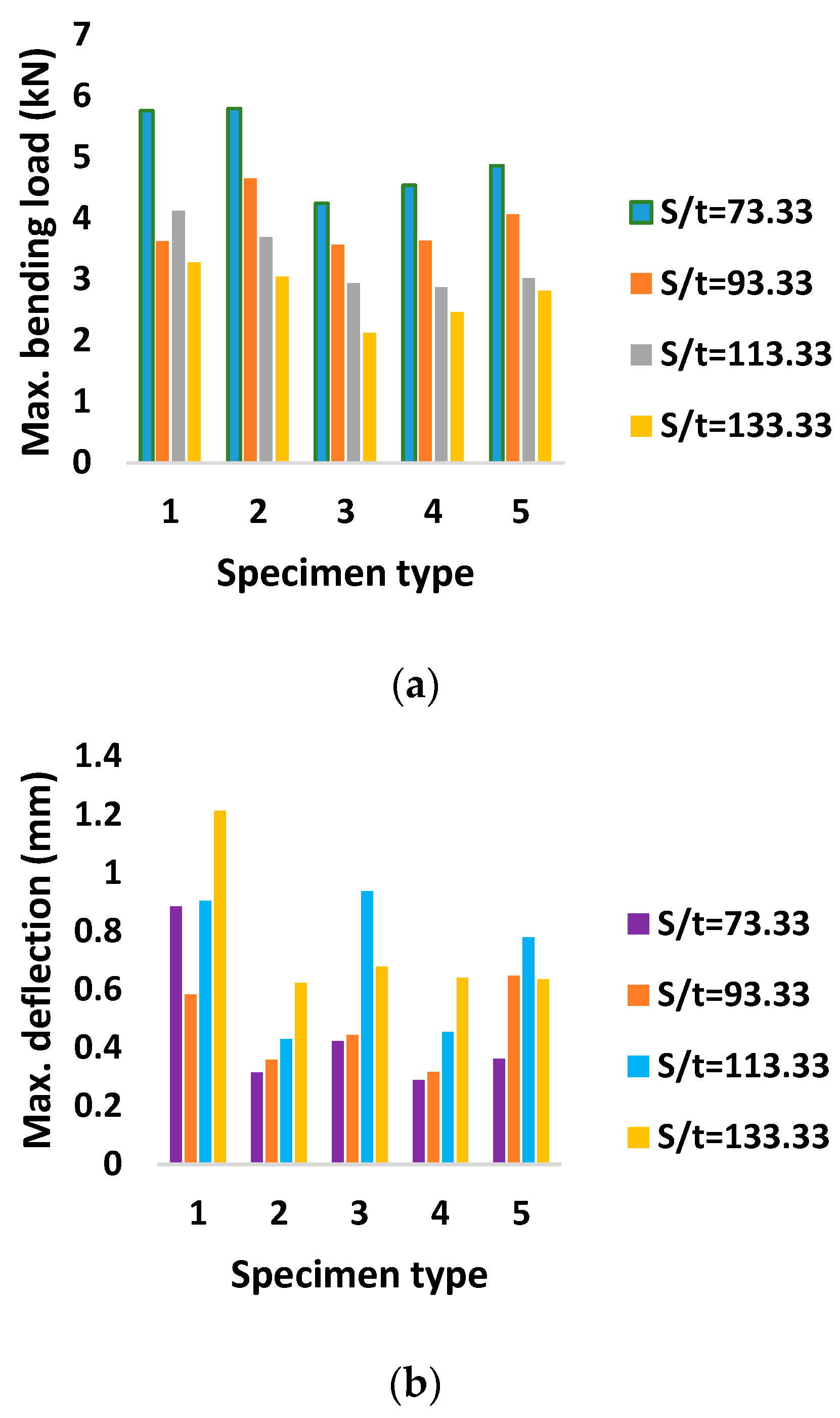
- The support span aspect ratio (S/t) significantly influenced the flexural behaviour of plain AHTs and AHTs with holes of different quantities and geometries.
- (ii)
- Following the support span aspect ratio, the type of discontinuity in terms of shape, size and quantity significantly influenced the flexural stability of AHTs. This may be due to the fact that these discontinuities acted as stress risers and influenced the flexural capacity of the structure to a larger extent.
- (iii)
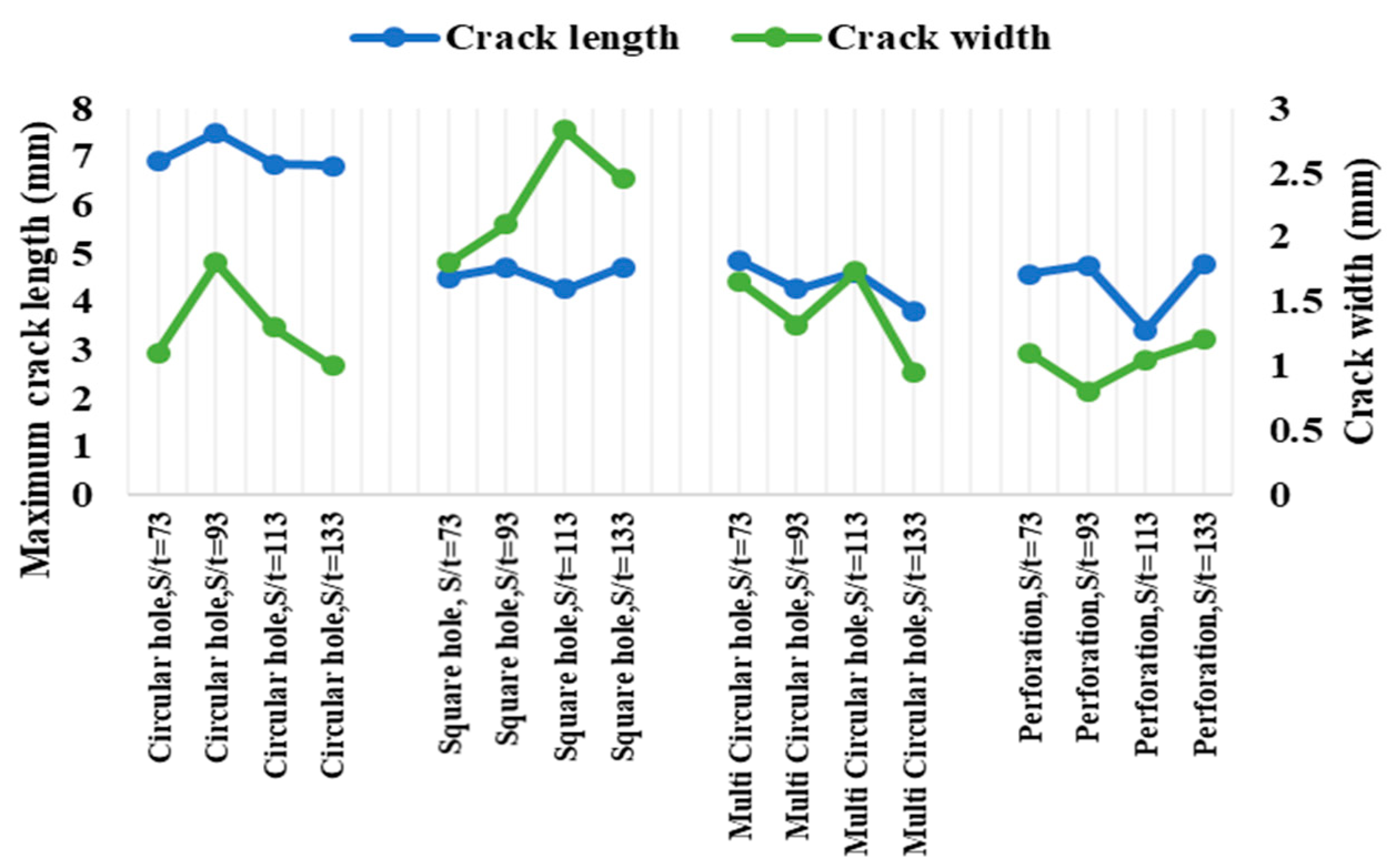
- AHTs with a circular hole, multiple circular holes and perforations were observed to have better flexural stability than that of other AHTs such as AHTs with square holes and plain AHTs. This may be attributed to the fact that the sharp corners in the holes are the sources of crack initiation and propagation, which in turn lead to the failure of the specimen under loading.
- (iv)
- Reducing the effect of stress concentration abruptly increased the flexural behaviour of AHTs by offering better flexural resistance.
- (v)
- The results obtained through experimental and numerical approaches complemented each other with utmost accuracy and consistency. The assumptions and constraints made during the analysis were very close and complemented each other.
Author Contributions
Funding
Institutional Review Board Statement
Informed Consent Statement
Data Availability Statement
Conflicts of Interest
References
- Scărlătescu, D.D.; Modrea, A.; Stanciua, M.D. Three-point bend test to determine the mechanical behavior of the tubes used in water supply networks. Procedia Manuf. 2019, 32, 179–186. [Google Scholar] [CrossRef]
- Zingaila, T.; Augonis, M.; Arruda, M.R.T.; Serelis, E.; Kelpsa, S. Experimental and numerical analysis of flexural concrete-UHPFRC/RC composite members. Mechanika 2017, 23, 182–189. [Google Scholar] [CrossRef]
- Tsai, M.-T.; Huang, P.S.; Yeh, J.H.; Liu, H.Y.; Chao, Y.C.; Tsai, F.; Chen, D.L.; Shih, M.K.; Tarng, D. Evaluation of three-point bending strength of thin silicon die with a consideration of geometric nonlinearity. IEEE Trans. Device Mater. Reliab. 2019, 19, 615–621. [Google Scholar] [CrossRef]
- Buyukkaragoz, A.; Kalkan, I.; Leec, J.H. A numerical study of the flexural behavior of concrete beams reinforced with afrp bars. Strength Mater. 2013, 45, 716–729. [Google Scholar] [CrossRef]
- Wang, S.; Zhang, J.; Zhou, Z.; Fang, G.; Wang, Y. Compressive and flexural behavior of carbon fiber-reinforced PPS composites at elevated temperature. Mech. Adv. Mater. Struct. 2020, 27, 286–294. [Google Scholar] [CrossRef]
- Shallal, M.A. Flexural behavior of concrete filled steel tubular beam. In Proceedings of the 2018 International Conference on Advance of Sustainable Engineering and Its Application (ICASEA), Wasit, Iraq, 14–15 March 2018; pp. 153–158. [Google Scholar] [CrossRef]
- Liu, Y.-B.; Cui, P.-P.; Chen, F. On factors behind the reasonable failure mode of concrete-filled circular steel tubular composite frame. Adv. Mater. Sci. Eng. 2021, 2021, 3027640. [Google Scholar] [CrossRef]
- Al Zand, A.W.; Ali, M.M.; Al-Ameri, R.; Badaruzzaman, W.H.W.; Tawfeeq, W.M.; Hosseinpour, E.; Yaseen, Z.M. Flexural Strength of Internally Stiffened Tubular Steel Beam Filled with Recycled Concrete Materials. Materials 2021, 14, 6334. [Google Scholar] [CrossRef]
- Tuan, C.Y. Flexural behavior of non-posttensioned and posttension concrete filled circular steel tubes. J. Struct. Eng. 2008, 134, 1057–1060. [Google Scholar] [CrossRef]
- Aydna, A.C.; Bayraka, B.; Maali, B.; Mete, E.; Cebi, K.; Kilic, M. The shear and flexural behavior of cold-formed steel composite I and U beams. Sci. Iran. A 2020, 28, 2119–2132. [Google Scholar] [CrossRef]
- Zahedi, L.; Oskouei, A.V.; Rajaee, S. A Numerical Study on Steel Tubes Wrapped with CFRP Laminates: Carbon Fiber Reinforced Polymers Applications on Offshore Marine Structures. Int. J. Constr. Environ. 2013, 3, 75–86. [Google Scholar] [CrossRef]
- Ibrahim, A.M.; Salman, W.D.; Bahlol, F.M. Flexural behavior of concrete composite beams with row steel tube section and different shear connectors. Tikrit J. Eng. Sci. 2019, 26, 51–61. [Google Scholar] [CrossRef]
- Marcadon, V.; Kurch, S. Roles of mechanical heterogeneities and damage on the overall mechanical behaviour of hollow-tube stackings. Eng. Procedia 2011, 10, 2815–2820. [Google Scholar] [CrossRef]
- Rong, B.; Guo, Y.; Li, Z. Study on the stability behavior of 7A04-T6 aluminum alloy square and rectangular hollow section columns under axial compression. Build. Eng. 2022, 45, 103652. [Google Scholar] [CrossRef]
- Awad, Y.D.; Al-Ahmed, A.H.A. Performance of hollow core concrete slab reinforced by embedded steel tubes. Assoc. Arab. Univ. J. Eng. Sci. 2019, 26, 17–21. [Google Scholar] [CrossRef]
- Zhou, J.; Wen, Z.; Mao, W.; Zhong, C.; Wang, K.; Zhou, C. Full-Scale Model Experimental Study of the Flexural Behavior of Hollow Slabs Strengthened by UHPC. Adv. Mater. Sci. Eng. 2021, 2021, 5581022. [Google Scholar] [CrossRef]
- Nassiraei, H.; Rezadoost, P. Stress concentration factors in tubular T joints reinforced with external ring under in-plane bending moment. Ocean. Eng. 2022, 266, 112551. [Google Scholar] [CrossRef]
- Johannesssen, H.; Johannessen, O.H.; Costas, M.; Clausen, A.H.; Sønstabø, J.K. Experimental and numerical study of notched SHS made of different S355 steels. Constr. Steel Res. 2021, 182, 106673. [Google Scholar] [CrossRef]
- Barbosa de Oliveira, M.A.; Rodrigues da Cunha, R.; de Souza Picanço, M.; Carvalho de Oliveira, D.R.; Leal Soares Ramos, E.M.; Pereira-da-Silva, M. Analysis of the influence of test method and properties of steel fiber addition on concrete under the three-point flexural tensile. Ingeniare. Rev. Chil. Ing. 2020, 28, 373–382. [Google Scholar] [CrossRef]
- Diab, H.M.; Abdelaleem, T.; Rashwan, M.M.M. Flexural behavior of RC continuous t-beams reinforced with hybrid CFRP/ steel bars: Experimental and numerical study”. J. Eng. Sci. Assiut Univ. Fac. Eng. 2021, 49, 215–247. [Google Scholar] [CrossRef]
- Ganesh, R.; Saravanan, M. Effect of fiber orientation on mechanical behavior of glass fiber reinforced polyethylene terephthalate foam sandwich composite. Mater. Today Proc. 2022, 62, 624–628. [Google Scholar] [CrossRef]
- Radhakrishnan, G.; Hattali, A.; Haitham, A.; Al Yahyai, A.M.; Al Riyami, A.M.; Al Hadhrami, A.M. Experimental study on the effect of aspect ratio on flexural behavior of Aluminium Sandwich Composite. Eng. Technol. J. 2022, 40, 990–995. [Google Scholar] [CrossRef]


| Chemical Element | % Present |
|---|---|
| Manganese | 0.0–0.15 |
| Iron | 0.0–0.7 |
| Magnesium | 0.80–1.2 |
| Silicon | 0.40–0.8 |
| Copper | 0.14–0.4 |
| Zinc | 0.0–0.25 |
| Titanium | 0.0–0.15 |
| Chromium | 0.04–0.35 |
| Others | 0.0–0.14 |
| Aluminium | Balance |
| Property | Value |
|---|---|
| Mass density | 2.7 g/cm³ |
| Melting Point | 652 °C |
| Thermal expansion | 23.4 × 10⁻⁶/K |
| Modulus of Elasticity | 71 GPa |
| Thermal conductivity | 168 W/mK |
| Electrical resistivity | 0.042 × 10⁻⁶ Ωm |
| Proof stress | 245 MPa |
| Tensile strength | 255 MPa |
| Brinell hardness | 94.5 HB |
| S. No. | Specimen | Stress Concentration Factor (K) | S/t | Maximum Bending Load (kN) | Maximum Deflection (mm) | Flexural Stiffness (kN/mm) |
|---|---|---|---|---|---|---|
| 1 | Plain | 1 | 73.33 | 5.759 | 0.884 | 6.515 |
| 2 | 93.33 | 3.624 | 0.583 | 6.216 | ||
| 3 | 113.33 | 4.12 | 0.904 | 4.558 | ||
| 4 | 133.33 | 3.275 | 1.213 | 2.700 | ||
| 5 | Circular hole | 1.007 | 73.33 | 5.791 | 0.314 | 18.443 |
| 6 | 93.33 | 4.651 | 0.358 | 12.992 | ||
| 7 | 113.33 | 3.691 | 0.429 | 8.604 | ||
| 8 | 133.33 | 3.039 | 0.622 | 4.886 | ||
| 9 | Square hole | 1.01 | 73.33 | 4.243 | 0.423 | 10.031 |
| 10 | 93.33 | 3.568 | 0.444 | 8.036 | ||
| 11 | 113.33 | 2.936 | 0.936 | 3.137 | ||
| 12 | 133.33 | 2.123 | 0.677 | 3.136 | ||
| 13 | Multiple circular holes | 1.01 | 73.33 | 4.535 | 0.288 | 15.747 |
| 14 | 93.33 | 3.634 | 0.317 | 11.464 | ||
| 15 | 113.33 | 2.867 | 0.454 | 6.315 | ||
| 16 | 133.33 | 2.464 | 0.639 | 3.856 | ||
| 17 | Perforation | 1.014 | 73.33 | 4.856 | 0.362 | 13.414 |
| 18 | 93.33 | 4.063 | 0.647 | 6.280 | ||
| 19 | 113.33 | 3.016 | 0.779 | 3.872 | ||
| 20 | 133.33 | 2.808 | 0.634 | 4.429 |
| S. No. | Specimen | Stress Concentration Factor (K) | S/t | Maximum Bending Load (kN) | Maximum Deflection (mm) | Flexural Stiffness (kN/mm) |
|---|---|---|---|---|---|---|
| 1 | AHT with circular hole | 1 | 73.33 | 5.953 | 0.465 | 12.802 |
| 2 | 93.33 | 5.375 | 0.865 | 6.214 | ||
| 3 | 113.33 | 2.774 | 0.8 | 3.468 | ||
| 4 | 133.33 | 1.625 | 0.763 | 2.130 | ||
| 5 | AHT with square hole | 1.007 | 73.33 | 4.931 | 0.388 | 12.709 |
| 6 | 93.33 | 4.087 | 0.663 | 6.164 | ||
| 7 | 113.33 | 2.3 | 0.668 | 3.443 | ||
| 8 | 133.33 | 1.503 | 0.711 | 2.114 | ||
| 9 | AHT with multiple circular holes | 1.01 | 73.33 | 4.566 | 0.362 | 12.613 |
| 10 | 93.33 | 2.429 | 0.397 | 6.118 | ||
| 11 | 113.33 | 2.047 | 0.599 | 3.417 | ||
| 12 | 133.33 | 1.173 | 0.559 | 2.098 | ||
| 13 | AHT with perforation | 1.01 | 73.33 | 5.513 | 0.437 | 12.616 |
| 14 | 93.33 | 2.613 | 0.427 | 6.119 | ||
| 15 | 113.33 | 1.756 | 0.514 | 3.416 | ||
| 16 | 133.33 | 1.368 | 0.652 | 2.098 | ||
| 17 | AHT with circular hole | 1.014 | 73.33 | 4.855 | 0.683 | 7.108 |
| 18 | 93.33 | 4.942 | 0.828 | 5.969 | ||
| 19 | 113.33 | 3.216 | 0.965 | 3.333 | ||
| 20 | 133.33 | 1.865 | 0.911 | 2.047 |
| S. No. | Specimen | Aspect Ratio (S/t) | Stress Concentration Factor (K) | Crack Width (mm) | Crack Length (mm) |
|---|---|---|---|---|---|
| 1 | AHT with circular hole | 73 | 1.007 | 1.1 | 6.9 |
| 2 | 93 | 1.8 | 7.5 | ||
| 3 | 113 | 1.3 | 6.85 | ||
| 4 | 133 | 1 | 6.8 | ||
| 5 | AHT with square hole | 73 | 1.01 | 1.8 | 4.5 |
| 6 | 93 | 2.1 | 4.7 | ||
| 7 | 113 | 2.83 | 4.25 | ||
| 8 | 133 | 2.45 | 4.7 | ||
| 9 | AHT with multiple circular holes | 73 | 1.01 | 1.66 | 4.85 |
| 10 | 93 | 1.32 | 4.25 | ||
| 11 | 113 | 1.73 | 4.6 | ||
| 12 | 133 | 0.95 | 3.8 | ||
| 13 | AHT with perforation | 73 | 1.014 | 1.1 | 4.56 |
| 14 | 93 | 0.8 | 4.75 | ||
| 15 | 113 | 1.05 | 3.4 | ||
| 16 | 133 | 1.2 | 4.78 |
Disclaimer/Publisher’s Note: The statements, opinions and data contained in all publications are solely those of the individual author(s) and contributor(s) and not of MDPI and/or the editor(s). MDPI and/or the editor(s) disclaim responsibility for any injury to people or property resulting from any ideas, methods, instructions or products referred to in the content. |
© 2023 by the authors. Licensee MDPI, Basel, Switzerland. This article is an open access article distributed under the terms and conditions of the Creative Commons Attribution (CC BY) license (https://creativecommons.org/licenses/by/4.0/).
Share and Cite
Radhakrishnan, G.; Breaz, D.; Al Khusaibi, S.S.; Al Subaihi, A.J.; Al Ismaili, A.A.Z.; AlMaani, A.M.; Karthikeyan, K.R. Experimental and Numerical Study on the Influence of Stress Concentration on the Flexural Stability of an Aluminium Hollow Tube. Materials 2023, 16, 1492. https://doi.org/10.3390/ma16041492
Radhakrishnan G, Breaz D, Al Khusaibi SS, Al Subaihi AJ, Al Ismaili AAZ, AlMaani AM, Karthikeyan KR. Experimental and Numerical Study on the Influence of Stress Concentration on the Flexural Stability of an Aluminium Hollow Tube. Materials. 2023; 16(4):1492. https://doi.org/10.3390/ma16041492
Chicago/Turabian StyleRadhakrishnan, Ganesh, Daniel Breaz, Sami Sulaiman Al Khusaibi, Amjad Juma Al Subaihi, Al Azhar Zahir Al Ismaili, AlSalt Malik AlMaani, and Kadhavoor R. Karthikeyan. 2023. "Experimental and Numerical Study on the Influence of Stress Concentration on the Flexural Stability of an Aluminium Hollow Tube" Materials 16, no. 4: 1492. https://doi.org/10.3390/ma16041492
APA StyleRadhakrishnan, G., Breaz, D., Al Khusaibi, S. S., Al Subaihi, A. J., Al Ismaili, A. A. Z., AlMaani, A. M., & Karthikeyan, K. R. (2023). Experimental and Numerical Study on the Influence of Stress Concentration on the Flexural Stability of an Aluminium Hollow Tube. Materials, 16(4), 1492. https://doi.org/10.3390/ma16041492