Systematic Experimental Investigation into the Determination of Micromechanical Properties of Hardened Cement Paste Using Nanoindentation—Opportunities and Limitations


Abstract
:1. Introduction
2. Materials and Methods
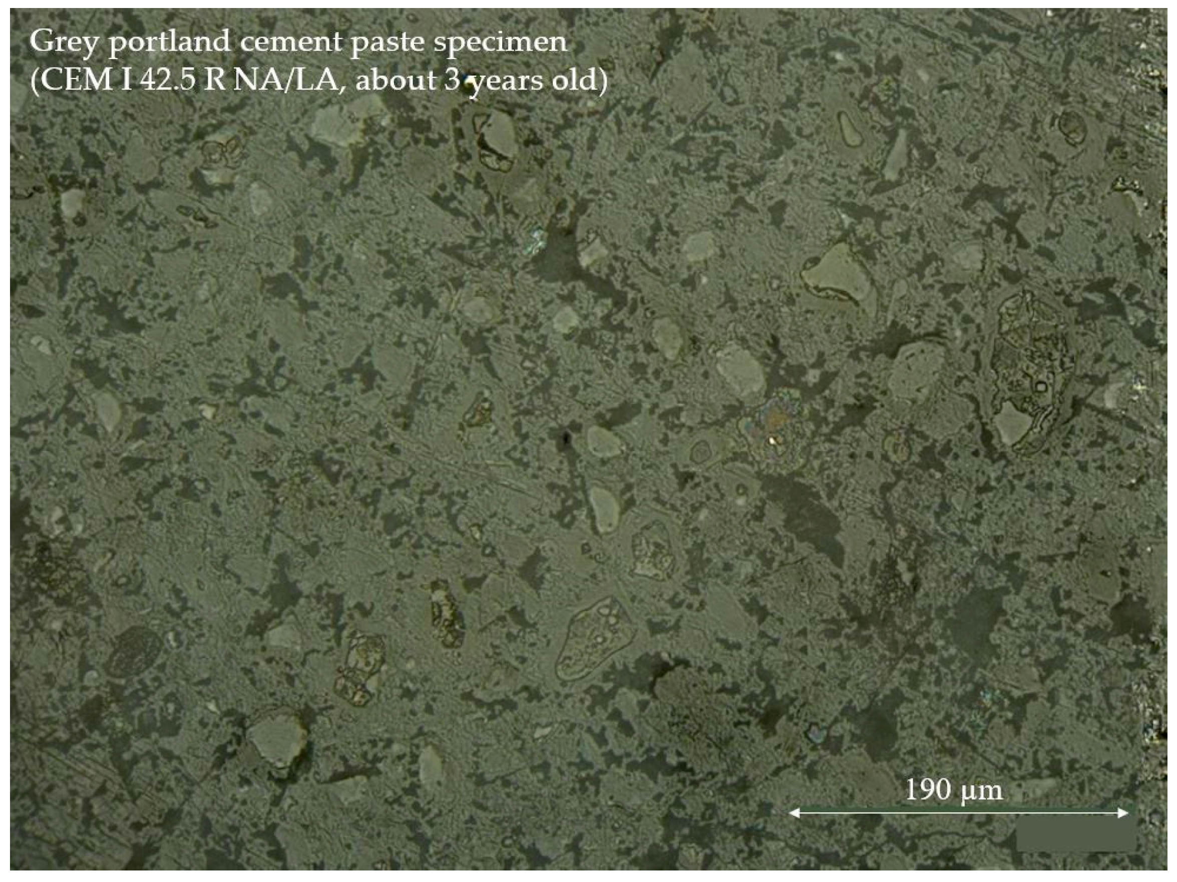
2.1. Sample Manufacturing and Surface Preparation
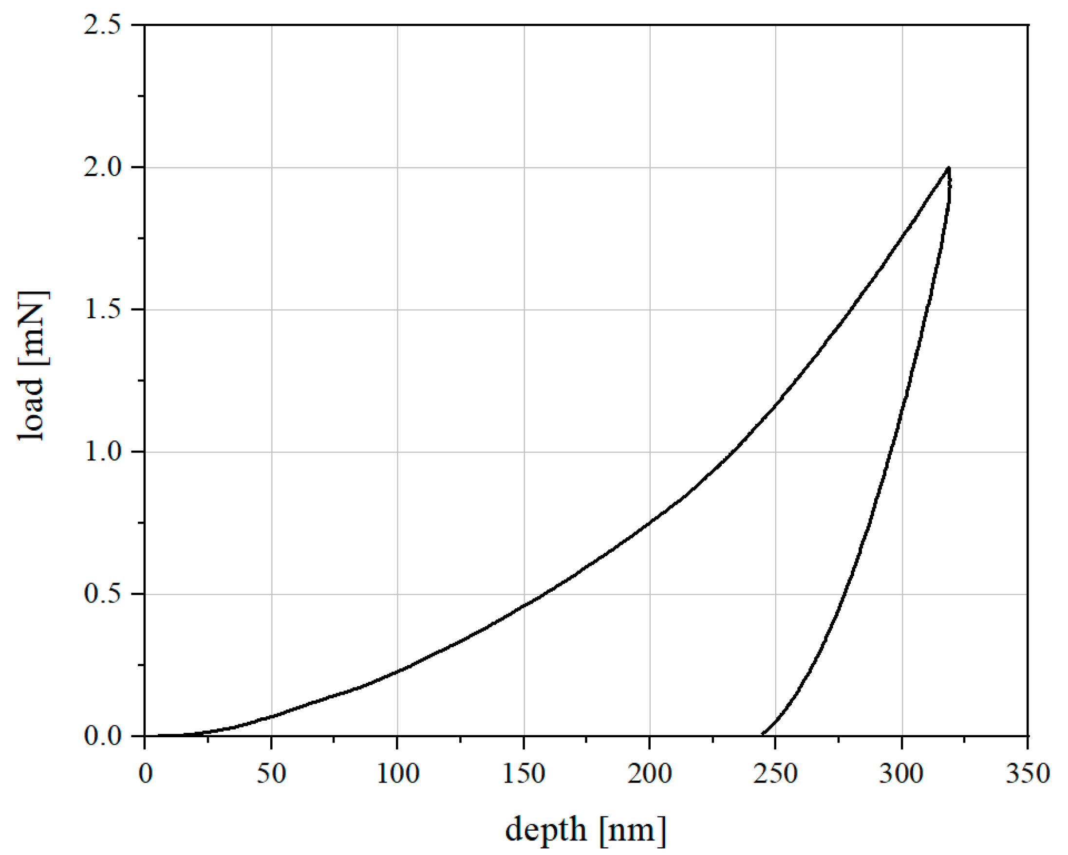
2.2. Nanoindentation on Cement Paste
3. Results and Discussion
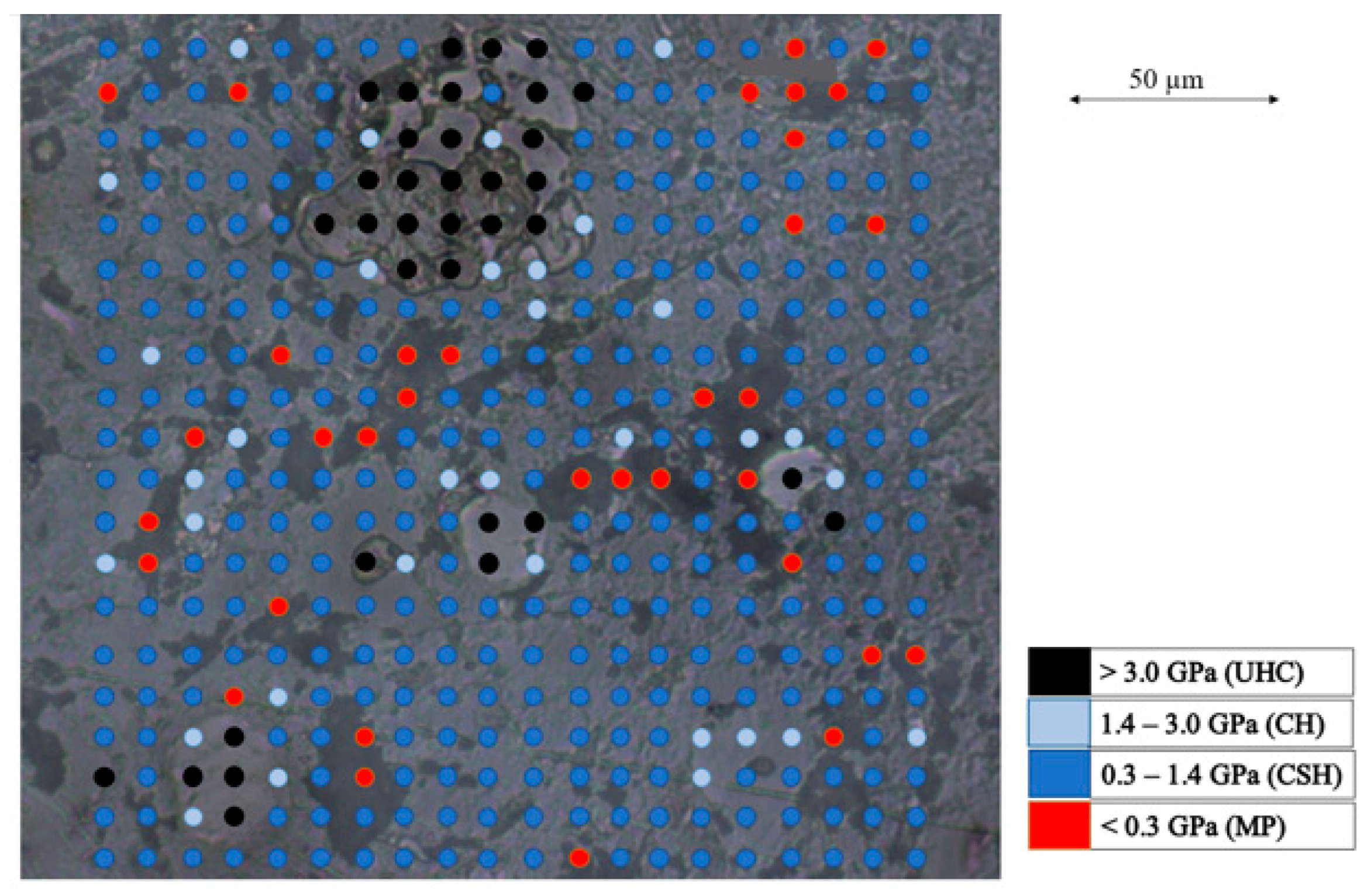
3.1. Statistical Analysis
3.2. Measurement Settings
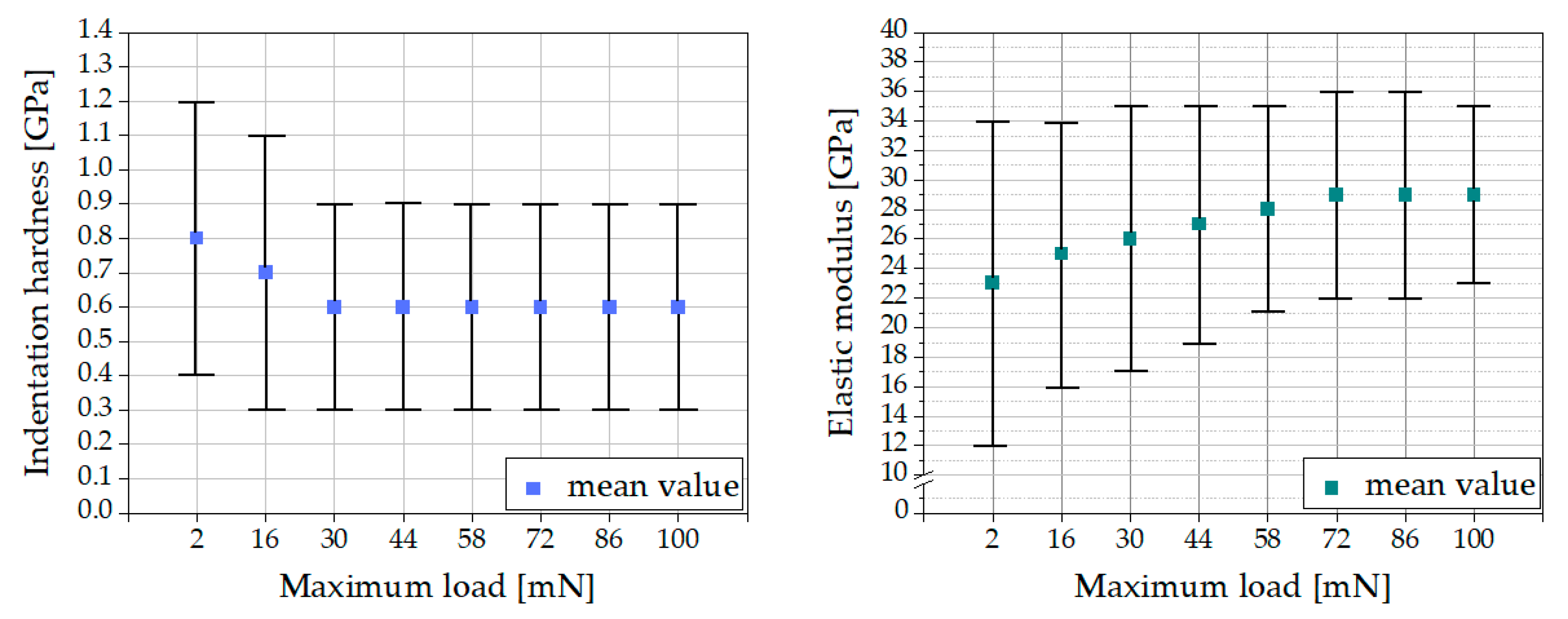
3.2.1. Maximum Load
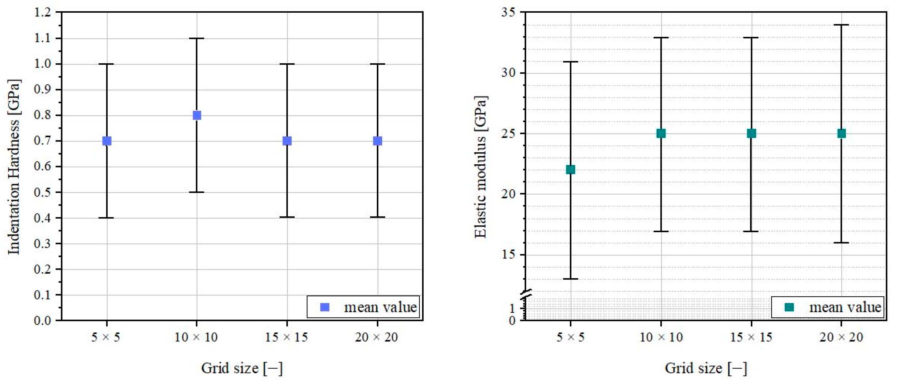
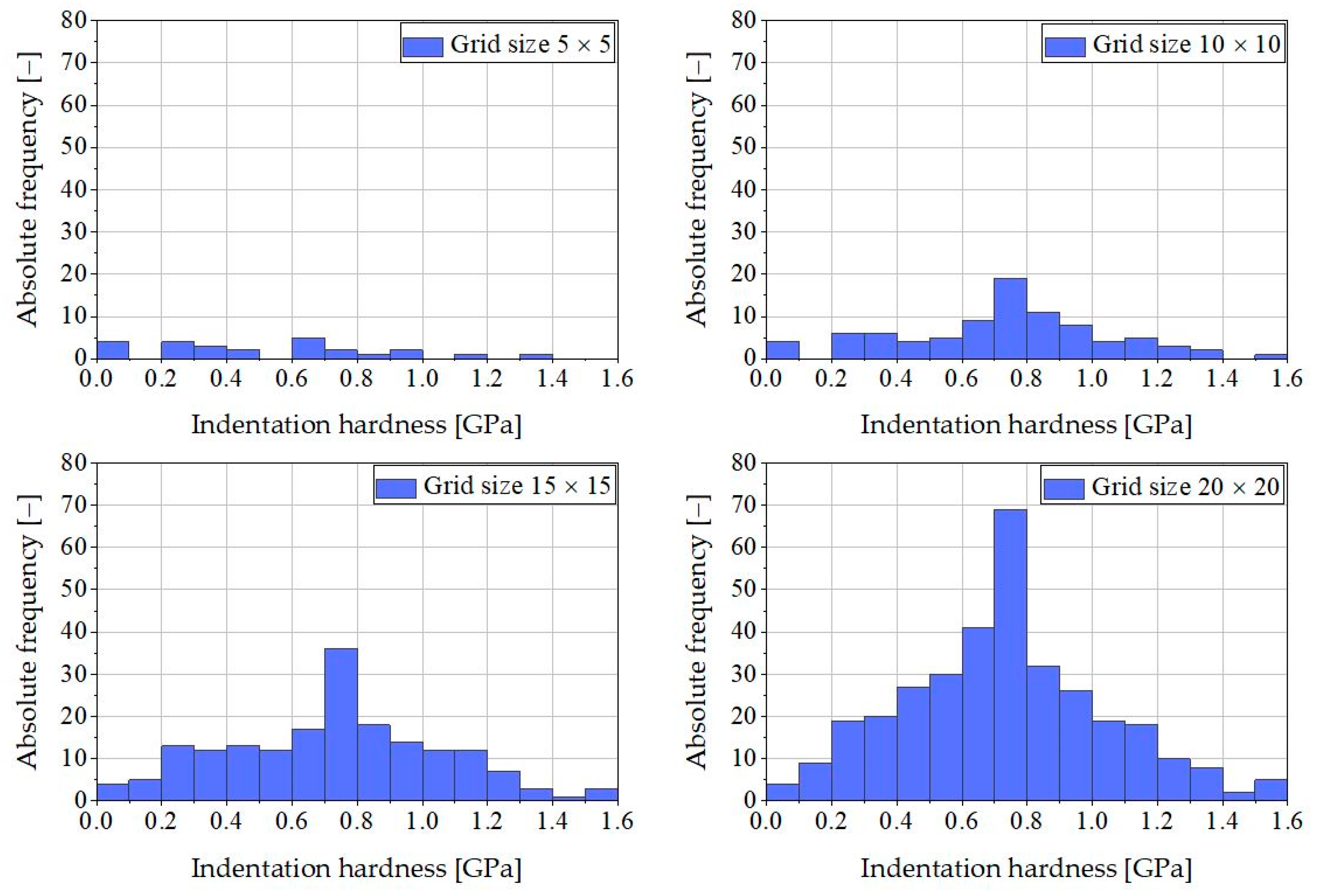
3.2.2. Grid Size
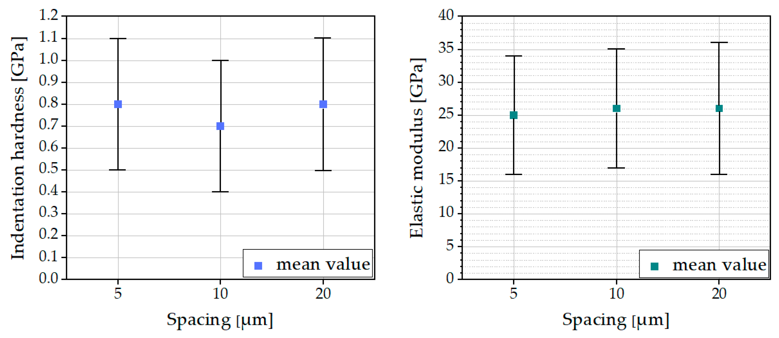
3.2.3. Spacing
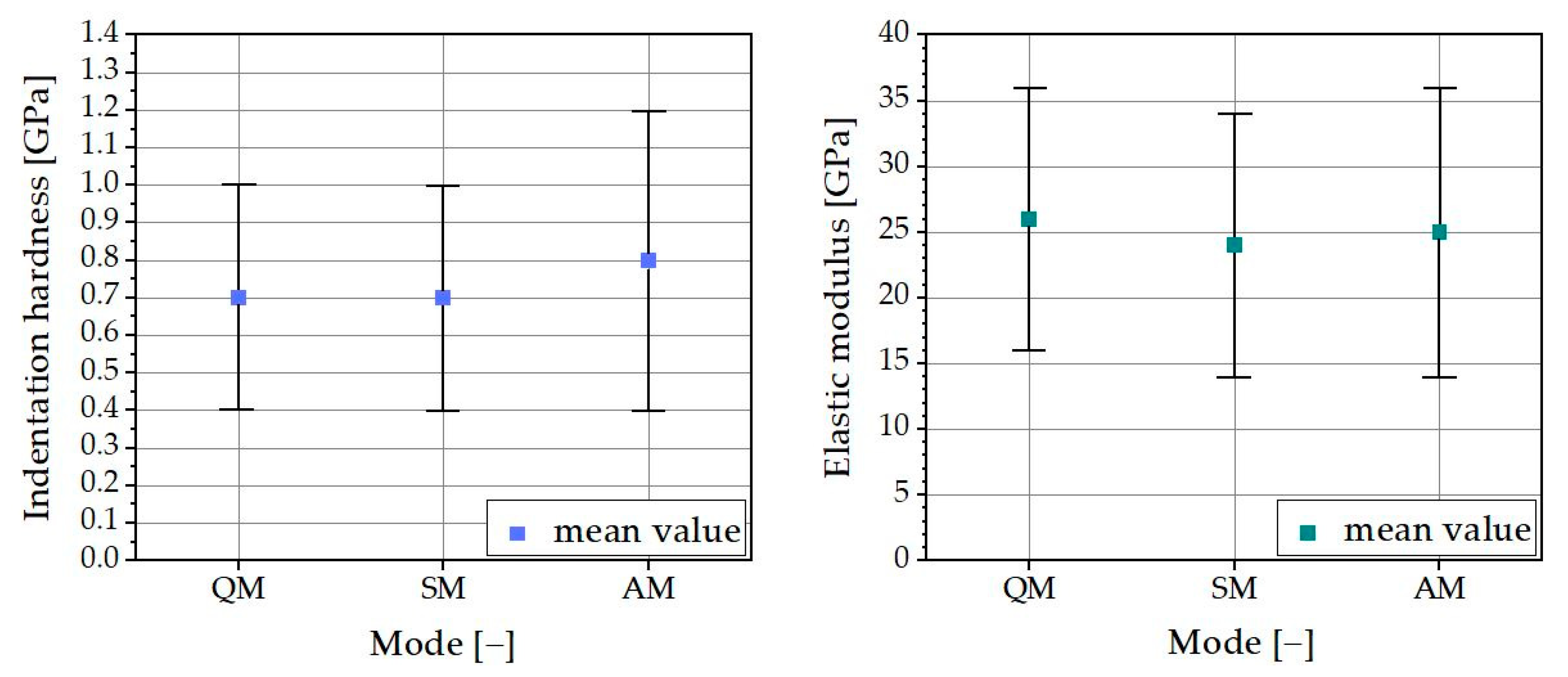
3.2.4. Mode
3.3. Surface Preparation
4. Summary and Conclusions
5. Further Research
Author Contributions
Funding
Institutional Review Board Statement
Informed Consent Statement
Data Availability Statement
Conflicts of Interest
References
- Hu, C.; Li, Z. A review on the mechanical properties of cement-based materials measured by nanoindentation. Constr. Build. Mater. 2015, 90, 80–90. [Google Scholar] [CrossRef]
- Constantinides, G.; Ulm, F.-J. The nanogranular nature of C-S-H. J. Mech. Phys. Solids 2007, 55, 64–90. [Google Scholar] [CrossRef]
- Foley, E.M.; Kim, J.J.; Reda Taha, M.M. Synthesis and nano-mechanical characterization of calcium-silicate-hydrate (C-S-H) made with 1.5 CaO/SiO2 mixture. Cem. Concr. Res. 2012, 42, 1225–1232. [Google Scholar] [CrossRef]
- Němeček, J. Creep effects in nanoindentation of hydrated phases of cement pastes. Mater. Charact. 2009, 60, 1028–1034. [Google Scholar] [CrossRef]
- He, Z.; Qian, C.; Zhang, Y.; Zhao, F.; Hu, Y. Nanoindentation characteristics of cement with different mineral admixtures. Sci. China Technol. Sci. 2013, 56, 1119–1123. [Google Scholar] [CrossRef]
- Rong, Z.D.; Sun, W.; Xiao, H.J.; Wang, W. Effect of silica fume and fly ash on hydration and microstructure evolution of cement based composites at low water–binder ratios. Constr. Build. Mater. 2014, 51, 446–450. [Google Scholar] [CrossRef]
- Hou, P.; Kawashima, S.; Kong, D.; Corr, D.J.; Qian, J.; Shah, S.P. Modification effects of colloidal nanoSiO2 on cement hydration and its gel property. Compos. Part B Eng. 2013, 45, 440–448. [Google Scholar] [CrossRef]
- Hafshejani, T.M.; Feng, C.; Wohlgemuth, J.; Krause, F.; Bogner, A.; Dehn, F.; Thissen, P. Effect of polymer-coated silica particles in a Portland cement matrix via in-situ infrared spectroscopy. J. Compos. Mater. 2021, 55, 475–488. [Google Scholar] [CrossRef]
- Němeček, J.; Šmilauer, V.; Kopecký, L. Nanoindentation characteristics of alkali-activated aluminosilicate materials. Cem. Concr. Compos. 2011, 33, 163–170. [Google Scholar] [CrossRef]
- Miller, M.; Bobko, C.; Vandamme, M.; Ulm, F.-J. Surface roughness criteria for cement paste nanoindentation. Cem. Concr. Res. 2008, 38, 467–476. [Google Scholar] [CrossRef]
- Han, J.; Pan, G.; Sun, W.; Wang, C.; Cui, D. Application of nanoindentation to investigate chemomechanical properties change of cement paste in the carbonation reaction. Sci. China Technol. Sci. 2012, 55, 616–622. [Google Scholar] [CrossRef]
- Ulm, F.-J.; Vandamme, M.; Bobko, C.; Alberto Ortega, J.; Tai, K.; Ortiz, C. Statistical Indentation Techniques for Hydrated Nanocomposites: Concrete, Bone, and Shale. J. Am. Ceram. Soc. 2007, 90, 2677–2692. [Google Scholar] [CrossRef]
- Němeček, J. Nanoindentation of Heterogeneous Structural Materials; Czech Technical University in Prague: Prague, Czech Republic, 2009. [Google Scholar]
- DIN EN 197-1:2011-11; Cement—Part 1: Composition, Specifications and Conformity Criteria for Common Cements. Beuth Verlag GmbH: Berlin, Germany, 2011.
- Wang, X.H.; Jacobsen, S.; He, J.Y.; Zhang, Z.L.; Lee, S.F.; Lein, H.L. Application of nanoindentation testing to study of the interfacial transition zone in steel fiber reinforced mortar. Cem. Concr. Res. 2009, 39, 701–715. [Google Scholar] [CrossRef]
- Wilson, W.; Rivera-Torres, J.M.; Sorelli, L.; Durán-Herrera, A.; Tagnit-Hamou, A. The micromechanical signature of high-volume natural pozzolan concrete by combined statistical nanoindentation and SEM-EDS analyses. Cem. Concr. Res. 2017, 91, 1–12. [Google Scholar] [CrossRef]
- BUEHLER SumMet. The Sum of Our Experience. A Guide to Materials Preparation & Analysis; Buehler: Lake Bluff, IL, USA, 2007. [Google Scholar]
- Software Manual Indentation-Version 8; Anton Paar GmbH: Graz, Austria, 2018.
- Oliver, W.C.; Pharr, G.M. An improved technique for determining hardness and elastic modulus using load and displacement sensing indentation experiments. Metrologia 1992, 7, 1564–1583. [Google Scholar] [CrossRef]
- Oliver, W.C.; Pharr, G.M. Measurement of hardness and elastic modulus by instrumented indentation: Advances in understanding and refinements to methodology. Metrologia 2004, 19, 3–20. [Google Scholar] [CrossRef]
- Xu, L.; Deng, F.; Chi, Y. Nano-mechanical behavior of the interfacial transition zone between steel-polypropylene fiber and cement paste. Constr. Build. Mater. 2017, 145, 619–638. [Google Scholar] [CrossRef]
- Mencik, J. Uncertainties and Errors in Nanoindentation. In Nanoindentation in Materials Science; InTech: Rijeka, Croatia, 2012. [Google Scholar]
- DIN EN ISO 14577; Metallische Werkstoffe. Instrumentierte Eindringprüfung zur Bestimmung der Härte und anderer Werkstoffparameter. Beuth Verlag GmbH: Berlin, Germany, 2015.
- Jia, Z.; Han, Y.; Zhang, Y.; Qiu, C.; Hu, C.; Li, Z. Quantitative characterization and elastic properties of interfacial transition zone around coarse aggregate in concrete. J. Wuhan Univ. Technol.-Mater. Sci. Ed. 2017, 32, 838–844. [Google Scholar] [CrossRef]
- Xie, R.; Lu, L.; Qiao, P.; Zhou, Z. Nanoindentation-based micromechanical characterisation of ultra-high-performance concrete exposed to freezing-thawing. Mag. Concr. Research. 2022, 74, 162–176. [Google Scholar] [CrossRef]
- Brown, L.; Allison, P.G.; Sanchez, F. Use of nanoindentation phase characterization and homogenization to estimate the elastic modulus of heterogeneously decalcified cement pastes. Mater. Des. 2018, 142, 308–318. [Google Scholar] [CrossRef]
- Qian, C.; Nie, Y.; Cao, T. Sulphate attack-induced damage and micro-mechanical properties of concrete characterized by nano-indentation coupled with X-ray computed tomography. Struct. Concr. 2016, 17, 96–104. [Google Scholar] [CrossRef]
- Hu, C.; Gautam, B.P.; Panesar, D.K. Nano-mechanical properties of alkali-silica reaction (ASR) products in concrete measured by nano-indentation. Constr. Build. Mater. 2018, 158, 75–83. [Google Scholar] [CrossRef]
- Li, L.; Li, Z.; Cao, M.; Tang, Y.; Zhang, Z. Nanoindentation and porosity fractal dimension of calcium carbonate whisker reinforced cement paste after elevated temperatures (up to 900 °C). Fractals 2021, 29. [Google Scholar] [CrossRef]
- Fédération Internationale du Béton (FIB). Model Code for Service Life Design. Fib Bull. 2006, 34, 116. [Google Scholar] [CrossRef]
- Fagerlund, G. A Service Life Model for Internal Frost Damage in Concrete; Report TVBM; Division of Building Materials, LTH, Lund University: Lund, Sweden, 2004. [Google Scholar]
- Jiang, J.; Zhang, D.; Gong, F.; Zhi, D. Prediction of Ultrasonic Pulse Velocity for Cement, Mortar, and Concrete through a Multiscale Homogenization Approach. Materials 2022, 15, 3241. [Google Scholar] [CrossRef]
- Gong, F.; Wang, Y.; Ueda, T.; Zhang, D. Modeling and Mesoscale Simulation of Ice-Strengthened Mechanical Properties of Concrete at Low Temperatures. J. Eng. Mech. 2017, 143, 6. [Google Scholar] [CrossRef]


| Adjust Depth Offset Parameters (ADO) | |
| Approach speed | 25,000 nm/min * |
| Contact force | 0.05 mN |
| Characterization force | 0.50 mN |
| Contact stiffness threshold | 150.0 μN/μm |
| Preapproach (indenter) | 10% |
| Preapproach (reference) | 40% |
| Contact force (reference) | 0.50 mN |
| Measurement preferences | |
| Indenter approach parameters | |
| Approach speed | 25,000 nm/min * |
| Approach distance | 2000 nm |
| Contact stiffness threshold | 150 μN/μm |
| Contact load | 0.02 mN |
| Reference approach parameters | |
| Approach speed | 60,000 nm/min * |
| Contact load | 0.02 mN |
| Preapproach | 40% |
| Reference–indenter autotuning | Active |
| Sensor ranges | |
| Reference load range | 20 mN |
| Indenter load range | 100 mN |
| Depth range | 10 μm |
Disclaimer/Publisher’s Note: The statements, opinions and data contained in all publications are solely those of the individual author(s) and contributor(s) and not of MDPI and/or the editor(s). MDPI and/or the editor(s) disclaim responsibility for any injury to people or property resulting from any ideas, methods, instructions or products referred to in the content. |
© 2023 by the authors. Licensee MDPI, Basel, Switzerland. This article is an open access article distributed under the terms and conditions of the Creative Commons Attribution (CC BY) license (https://creativecommons.org/licenses/by/4.0/).
Share and Cite
Raupach, K.; Bogner, A.; Vogel, M.; Kotan, E.; Dehn, F. Systematic Experimental Investigation into the Determination of Micromechanical Properties of Hardened Cement Paste Using Nanoindentation—Opportunities and Limitations. Materials 2023, 16, 1420. https://doi.org/10.3390/ma16041420
Raupach K, Bogner A, Vogel M, Kotan E, Dehn F. Systematic Experimental Investigation into the Determination of Micromechanical Properties of Hardened Cement Paste Using Nanoindentation—Opportunities and Limitations. Materials. 2023; 16(4):1420. https://doi.org/10.3390/ma16041420
Chicago/Turabian StyleRaupach, Kristina, Andreas Bogner, Michael Vogel, Engin Kotan, and Frank Dehn. 2023. "Systematic Experimental Investigation into the Determination of Micromechanical Properties of Hardened Cement Paste Using Nanoindentation—Opportunities and Limitations" Materials 16, no. 4: 1420. https://doi.org/10.3390/ma16041420
APA StyleRaupach, K., Bogner, A., Vogel, M., Kotan, E., & Dehn, F. (2023). Systematic Experimental Investigation into the Determination of Micromechanical Properties of Hardened Cement Paste Using Nanoindentation—Opportunities and Limitations. Materials, 16(4), 1420. https://doi.org/10.3390/ma16041420