Abstract
Prosthetic reconstructions provide anatomical reconstruction to replace bones and joints. However, these operations have a high number of short- and long-term complications. One of the main problems in surgery is that the implant remains in the body after the operation. The solution to this problem is to use biomaterial for the implant, but biomaterial does not have the required strength characteristics. The implant must also have a mesh-like structure so that the bone can grow into the implant. The additive manufacturing process is ideal for the production of such a structure. The study deals with the correlation between different prosthetic structures, namely, the relationship between geometry, mechanical properties and biological additivity. The main challenge is to design an endoprosthesis that will mimic the geometric structure of bone and also meet the conditions of strength, hardness and stiffness. In order to match the above factors, it is necessary to develop appropriate algorithms. The main objective of this study is to augment the algorithm to ensure minimum structural weight without changing the strength characteristics of the lattice endoprosthesis of long bones. The iterative augmentation process of the algorithm was implemented by removing low-loaded ribs. A low-loaded rib is a rib with a maximum stress that is less than the threshold stress. Values within the range (10, 13, 15, 16, 17, 18, 19 and 20 MPa) were taken as the threshold stress. The supplement to the algorithm was applied to the initial structure and the designed structure at threshold stresses σf = 10, 13, 15, 16, 17, 18, 19 and 20 MPa. A Pareto diagram for maximum stress and the number of ribs is plotted for all cases of the design: original, engineered and lightened structures. The most optimal was the designed “lightweight” structure under the condition σf = 17 MPa. The maximum stress was 147.48 MPa, and the number of ribs was 741. Specimens were manufactured using additive manufacturing and then tested for four-point bending.
1. Introduction
Nowadays, the number of operations involving arthroplasty is increasing day by day. However, some problems remain unresolved. One of the main particularities of arthroplasty is that the implant remains in the body after surgery. The solution to this problem is to make an implant using biomaterial, but biomaterial does not have the required strength characteristics [1,2]. The implant must also have a lattice structure in order for the bone material to grow through it. Additive manufacturing is an excellent solution for the production of such a structure.
Studies of the mesh structure produced by additive manufacturing techniques can improve the quality of endoprosthetics as a whole. Mesh structures printed in this way have sufficient strength and can also stimulate bone growth. Stimulation occurs, for example, by placing bone material inside [3,4,5]. Such structures would not be a complete substitute for a biomaterial prosthesis. However, there are currently a number of problems with the fabrication of biostructures.
Currently, the majority of endoprostheses are made of hard metal. Their main features are considered to be high biocompatibility and corrosion and wear resistance. However, the monolithic implants made of this material have higher stiffness than bone tissue. This property exposes the contact area between the endoprosthesis and the bone tissue to destruction [6]. The solution to this problem is the fabrication of mesh structures. Their design is based on factors such as strength and weight as well as a sufficient distance between the meshes for new tissue to take root. The retrofitting of mesh structures is still being investigated [7,8]. Studies have investigated the correlation between different prosthetic structures, namely, the relationship between geometry, mechanical properties and biological additivity. The main challenge is to design an endoprosthesis that will mimic the geometric structure of bone as well as meet the conditions of strength, hardness and stiffness.
Additive manufacturing allows the lattice structure to be manufactured in such a way that new tissues can grow and all mechanical parameters can be met, compared to the traditional manufacturing of lattice structures. The main disadvantage of this approach is considered to be the brittle properties of the structure and the deviation from the geometry during fusion [9,10,11,12,13]. There is also a trend toward manufacturing endoprostheses using composite materials [14]. Such systems combine calcium phosphate with ceramic or polymeric materials. This approach provides the necessary mechanical properties but is not suitable for individual implants. Selective laser melting technology is used to create an individual prosthesis. This method makes it possible to accurately produce an implant with a well-developed roughened surface [15,16,17].
Bone tissue is a complex anisotropic irregularly distributed regenerated material. Due to its heterogeneous structure, bone is constantly exposed to non-uniform loading, which results in a non-uniform stress–strain state. That is, such a structure is characterized by both overstressed areas and areas with insufficient loading. This fact should not be excluded when designing an endoprosthesis; an important task is to distribute the stress–strain state (SSS) evenly over the implant. In endoprosthesis design, a design with a regular distribution of cells is most commonly used. In this case, the structure can be considered as a certain topology. However, this approach does not result in all parts of the structure being evenly loaded. There is a question of modifying the structure in such a way as to minimize the amount of material used and to make uniform stress and strain distributions.
Previous studies have already addressed the design aspect of endoprostheses, achieving results to ensure that maximum stresses are reduced in an irregular, transversally isotropic design [14]. Nevertheless, there is no complex approach to the numerical and experimental study of lattice endoprosthesis design. Moreover, it is necessary to develop algorithms that enable us to construct the endoprosthesis with less weight and enhanced strength properties. Hence, the main objective of the present study is to provide an algorithm to obtain the minimal weight of the structure without decreasing the strength characteristics of the lattice endoprosthesis of long bones, as well as the verification of the numerical computations with experimental tests.
2. Materials and Methods
2.1. Brief Description of the Proposed Design Method
The lattice endoprosthesis (Figure 1c) is a set of blocks (Figure 1b). Each block consists of elementary cells (Figure 1a). In order to design a uniformly loaded product, we varied the dimensions of the blocks. The length of the blocks was varied using an influence function. Numerical experiments of the unit cell in compression and bending were performed to determine the influence function. The unit cell was described by the dimensionless parameter λ, which describes the ratio of its length to the radius of the circumscribed circle. The influence functions of parameter λ on the stress–strain state of the unit cell for compressive and bending loads have been obtained [14]. The idea of the algorithm was to determine the maximum normal stresses in each block and then modify the block lengths depending on the stresses while maintaining the product dimensions. The implant was optimized according to the previously proposed algorithm; the parameter vector was as follows: λ = (0.4, 0.4, 0.4, 0.4., 0.5, 0.8, 1.3, 1.7, 1.8, 2.3) [14]. The parameter vector λ is considered a vector with a 1xN dimension; each cell of the construction stores the value of the dimensionless parameter λ of the N-th block. Previously, we achieved a 53% reduction in maximum stresses compared to the original geometry [14]. However, we did not change the weight of the structure. The design Algorithm 1 presented in the previous paper is as follows:
| Algorithm 1 Endoprosthesis Design Algorithm |
| Input: vector of parameters λ = [1, 1, 1, 1, 1, 1, 1, 1, 1, 1] |
| Output: vector of parameters λ = [λ1, λ2,…, λ9, λ10] |
| Create geometry according to parameter vector λ |
| Create finite element mesh |
| Apply workloads and boundary conditions |
| SSS problem solution |
| For each block |
| Compute the maximum normal stresses in each block |
| Determine the vector of parameters λ depending on the influence functions of the elementary cell; |
| end |
| Check iteration stop condition |
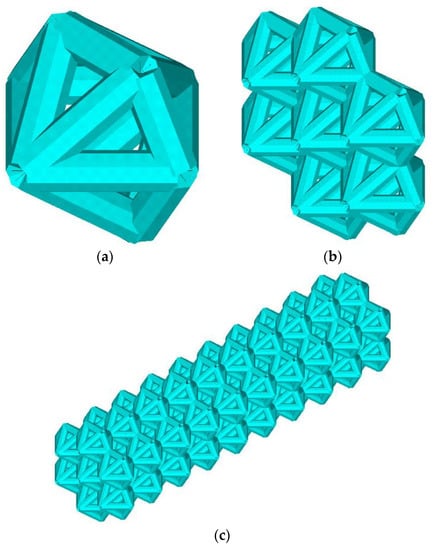
Figure 1.
Geometry. Elementary cells (a), block (b), lattice endoprosthesis (c).
As mentioned earlier, the addition of the algorithm aims to reduce the weight of the product. The idea behind the addition of the algorithm is to remove the low-stress ribs of the prosthesis. A low-stress rib is a rib with a maximum stress that is lower than the threshold stress. The threshold stress is subjectively determined but does not exceed 4% of the yield strength of the material. However, first of all, the operating range of the algorithm must be defined as the endoprosthesis must be able to accommodate the placement of the bone material.
2.2. Mathematical Formulation of the Problem
The mechanical behavior of the endoprosthesis, within the framework of linear elasticity theory, can be described as follows:
where V0—initial volume, σ—stress tensor, ε—strain tensor, E—stiffness tensor, Sk—area with kinematic boundary conditions, Sf—area with static boundary conditions, u—displacement vector, n—normal to the area with static boundary conditions, and Vcon—the constant region (Figure 2).
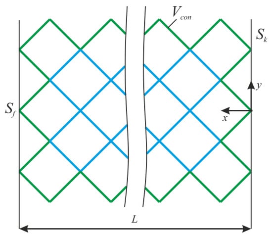
Figure 2.
The design of lattice endoprosthesis.
The design assumes that the endoprosthesis is manufactured using additive manufacturing. The material used is stainless steel PS4542A 17-4 PH: Young’s modulus 210 GPa, Poisson’s ratio 0.3, yield stress σY = 500 MPa. The load in the numerical calculations was applied as follows: F = (−3, 1, 7) N, where −3 N is the compressive load in the x-direction [14].
2.3. Algorithm of Constructing A Lattice Structure
The algorithm is carried out in the entire construction area, except for the area Vcon. For Vcon, we consider the frame and support ribs of the endoprosthesis (Figure 2). After solving the stress–strain problem, the normal level of stress was determined at each i-th node of the rib.
Maximum normal stress at i-th rib σmax(i) corresponds to the maximum stress arising at the rib nodes.
The threshold stress σf was taken as the values on the interval [2% σY; 4% σY]. The rib where σmax(i) < σf was deleted, and after that, the stress–strain state problem was solved again. This process is iterative and stops when σmax(i) > σf at all ribs.
The addition to the Algorithm 2 of the lattice endoprosthesis design is as follows:
| Algorithm 2 Addition to Endoprosthesis Design Algorithm |
| Input: vector of parameters λ = [λ1, λ2,…, λ9, λ10], edge numbers |
| Output: edge numbers |
| Create geometry according to parameter vector λ and face numbers |
| Create finite element mesh |
| Apply workloads and boundary conditions |
| Determine the area of operation of the algorithm |
| while flag |
| SSS problem solution |
| determine the maximum voltage σmax(i) |
| if σmax(i) < σf delete the i-th face |
| else go to i + 1 |
| Check iteration stop condition |
| end |
2.4. FE Mesh Convergence
The calculation was carried out with the ANSYS 2022 R1 software package. The finite element type was BEAM188 with quadratic approximation. The number of elements per edge was fifty. However, before the numerical calculation of the stress–strain state of an endoprosthesis, it is necessary to check the mesh convergence. The convergence of the mesh has been checked for one unit cell. The convergence of the mesh at the k-th node under the bending force F = −1 N can be seen in Figure 3. The k-th node is taken to be the node with the maximum stress that is not included in the area of boundary conditions. Based on the convergence of the mesh at the k-th node, in the subsequent design, for each edge, the number of elements equal to fifty was chosen. The error is 0.17%.
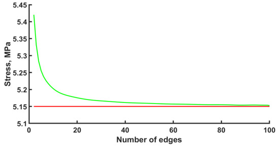
Figure 3.
Mesh convergence plot (green line—approximation, red line—plateau).
2.5. Experiment
Previously, in numerical calculations, it was shown that stress distribution does not depend on stiffness properties [18]. This can be explained by using a linear model in simulation. Such a fact allows the use of other materials in experiments. Of course, different materials have their own specific mechanical behavior, especially in the case of additive manufacturing. However, in an elastic region, this difference is minimal [19,20], especially if the same material specimens are used. That is why, because of economic expediency, the specimens were made from photopolymer resin.
To provide pure bending, a four-point bending scheme was used. Points of force application were located on the arms (outside the structure). In this case, the constant bending moment acts on the specimen. The scheme of the four-point bending test is shown in Figure 4. There was no compression in the experiments. On one hand, adding compression complicates the experimental rig. On the other hand, the bending test is more informative for exploitation. In the case of compression loading, it is known that the failure mechanism of lattice structures begins with buckling. Then, the bending component appears and boosts the destruction. However, the pure bending test allows us to estimate the loading in ribs and nodes without the buckling effect.
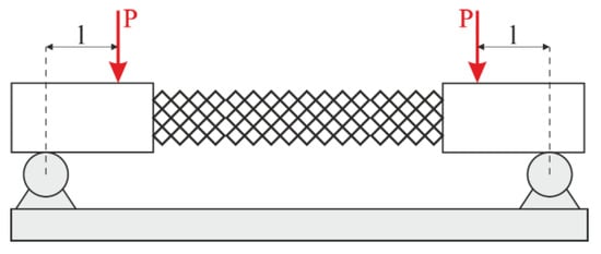
Figure 4.
Loading scheme.
To ensure metrological accuracy, the specimens were made on a scale of 2.5. The scale was determined based on the strength properties of the endoprosthesis in numerical experiments and the properties of the photopolymer resin. The scaling of the model is related to the low stiffness of the original endoprosthesis, as its length is 40 mm and the diameter of the rib is 0.4 mm. Additionally, the scaling effect was investigated.
Hence, the geometry of the endoprosthesis was reconstructed and manufactured using additive technologies. The samples were produced using an Anycubic Photon Mono X photopolymer 3d printer with a resolution of up to 10 µm. This was sufficient to produce the samples. Anycubic Basic photopolymer resin was used. The mechanical properties of the material were as follows: Young’s modulus 1.2 GPa, Poisson’s ratio 0.32, and tensile strength 23.4 MPa. Four-point bending tests were conducted according to the scheme shown in Figure 4. The specimen was mounted according to the bending plane with a numerical calculation scheme. Load curves were obtained, and the ultimate loads were analyzed.
3. Results
3.1. Lightening of the Original Construction
At the threshold stress σf = (2%, 3%, 4% σY), the maximum stresses in the structure were 155, 154, and 203 MPa, respectively (Figure 5). The number of ribs was 1015, 918, and 852, respectively. Compared to the initial geometry (1040 ribs), the number of ribs decreased to 2.4%, 11.7%, and 18%, respectively. As the threshold stress increases, a characteristic reduction in ribs in blocks 4–9 is observed. Maximal von Mises stress at σf = (2%, 3% σY) occurs in constrained zones (first block); von Mises stress at σf = 4% σY occurs in the zone of the ninth block.
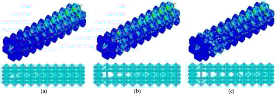
Figure 5.
Von Mises stress distribution and endoprosthesis view with initial geometry at σf = 2% σY (a), σf = 3% σY (b), and σf = 4% σY (c).
3.2. Lightening of the Updated Construction
At the threshold stress σf = (2%, 3%, 4% σY), the maximum stresses in the designed construction were 71.5, 169.2, and 251.4 MPa, respectively (Figure 6). The number of ribs was equal to 911, 776, and 699, respectively. Compared to the initial geometry, the number of ribs decreased to 12.4%, 25.3%, and 32.7%, respectively.
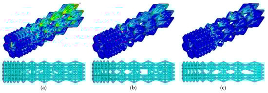
Figure 6.
Von Mises stress distribution and endoprosthesis view with updated geometry at σf = 2% σY (a), σf = 3% σY (b), and σf = 4% σY (c).
3.3. Pareto Diagram
Additionally, the algorithm was applied to the original design and the developed design at threshold stresses σf = (10, 13, 15, 16, 17, 18, 19, 20 MPa). The Pareto diagram shows the results of the algorithm for different designs: stress and number of ribs in the original structure (the red rhombus in Figure 7), the constructed structure (the green rhombus in Figure 7), the “lightweight” original structure λ = (1; 1; 1; 1; 1; 1; 1; 1; 1) (the red square in Figure 7), and the “lightweight” constructed structure λ = (0.4, 0.4, 0.4, 0.4., 0.5, 0.8, 1.3, 1.7, 1.8, 2.3) (the blue rhombus in Figure 7).
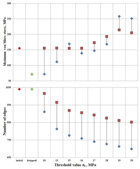
Figure 7.
Pareto diagram; red rhombus—original structure, green rhombus—designed structure, red square—“lightweight” structure at λ = (1; 1; 1; 1; 1; 1; 1; 1; 1), and blue rhombus—“lightweight” structure at λ = (0.4, 0.4, 0.4, 0.4., 0.5, 0.8, 1.3, 1.7, 1.8, 2.3).
The maximum stress in the original design is 155 MPa. Relaxation of the original design up to the threshold value σf = 16 MPa proceeds without a change in maximum stresses. Thus, having lightened the structure by 12.9%, the maximum stresses in the structure remained unchanged. Increasing the threshold to σf = 20 MPa, the number of ribs would decrease by 18%, but maximum tensions in the structure would increase by 32%. The value of σf = 16 MPa has been found to be the most appropriate threshold stress for relief of the original structure.
The maximum stress of the designed structure is 71.3 MPa. At design-induced lightening with the threshold value σf = 10 MPa, maximum stresses in the structure do not change. The number of ribs decreased by 12.3%. The lightweight design structure exhibits better strength properties than the original one. Up to the threshold value σf = 18 MPa, the maximum tension in the structure is 168.4 MPa at the reduction of the number of ribs by 30%.
The most optimal is the “lightened” design, provided σf = 17 MPa. The maximum stress was 147.48 MPa, and the number of ribs was 741. It can be concluded that by reducing the ribs by 28.7% relative to the original design, the stresses will decrease by 4.8%.
3.4. Experiment Results
Four samples of each design type were produced: initial, engineered, and lightweight at σf =17 MPa. Each specimen was tested according to the diagram shown in Figure 3. The length of the arm between the support and the applied load corresponds to l = 30 mm. The experimental setup with the designed specimen is shown in Figure 8a. The local fracture pattern of the designed sample is shown in Figure 8b.
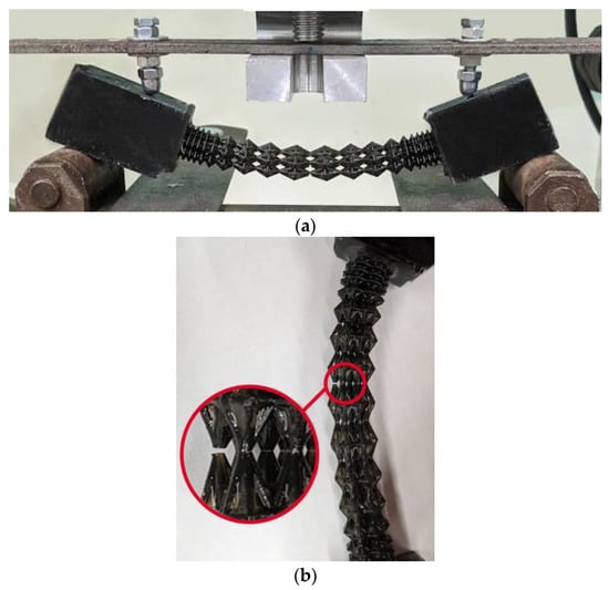
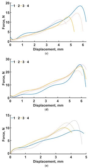
Figure 8.
Four-point bending diagram (a), local fracture pattern (b), loading curve for the original structure (c), loading curve for the designed structure (d), and loading curve for the lightweight structure (e). Numbers 1–4 are samples 1–4.
The loading curves for all sample types are shown in Figure 8c–e. In the four-point bending experiments for the original geometry (see Figure 8c), the maximum force was 18.4 N and the displacement was 6 mm. For the engineered design (see Figure 8d), the maximum force was 25.7 N and the displacement was 5.8 mm. For the lightweight design (see Figure 8e), the displacement was 4.29 mm, with a maximum force of 12.9 N. The average maximum force for the original, engineered, and lighter structures at σf =17 MPa is 14.3, 24.1, and 11 N, respectively.
In percentage terms, the difference in average over all samples in terms of maximum force between the original and engineered geometry is 68.5%. In the numerical experiments, the maximum stresses of the designed structure are 53% lower than those of the original design.
The average maximum force of the lightened specimens is 23% less than that of the original design. In the numerical calculation, this percentage was 4.3% in favor of the lightened design.
4. Discussion
Numerous factors play an important role when designing novel implants [21]. Convenient methods showed a lot of limitations for effective implementation in clinical practice because of rapidly growing requirements from society, starting from performance properties and ending with ergonomics and aesthetic appearance. Additive manufacturing is a promising tool to overcome several limitations of traditional methods of production [22]. Despite the enormous costs, the constant stimulation of development is vital to meet the needs of an aging society [23]. Thanks to the adaptability of the method, the geometry can be tailored more precisely to the actual requirements of the patients, thus effectively counteracting the problem of wear protection, in particular [24].
On one hand, the FEM may be an appropriate instrument to examine the mechanical impacts of the changed prosthesis geometry. A number of past works dealing with it have been published [23,25,26].
On the other hand, topology optimization provides a novel strategy to optimize mechanical work by redesigning the dispersion of fabric in an assigned space. This dissemination depends on the specialized loading and boundary condition limitations that are subject to the objective aim to play down or maximize certain properties of the structure. It has been shown that topology optimization methods enable us to attain new implants with better biomechanics [27].
Hence, we can design and create a larger contact area between the prosthesis and the bone so that better adhesion can be realized. Increased bone-implant contact surface areas lead to a higher connection strength [28].
Experimental and numerical studies have shown good strength properties for the designed endoprosthesis. However, for the lightweight design, the average maximum load in the experiment was lower than that of the original specimens. This may be due to variations in cell geometry. Recently, similar conclusions were exhibited by Niutta et al. [29]. The removal of the ribs compromised the self-sustaining property of the whole structure. In other words, during local failure (Figure 8b) of the unit cell of both the original and engineered structures, the stress–strain state was redistributed to low-loaded areas of the structure, as previously indirectly shown by Smith et al. [30]. The lightweight structure does not have this property.
If we consider the lightweight and original designs, we note the fact that there is an overlap in the maximum forces of some samples. In the original design, the mean maximum stress of all samples was 14.3 ± 3.08, and in the case of the lightweight version, it was 10.99 ± 1.7. Looking at the median value of maximum stress in the original design, it was 13.7, and in the lightweight version, it was 10.99. Increasing the number of test specimens can give us the average maximum value for these types of specimens.
The incorrectness of the results also depends on the method used to print these samples [31]. In this study, the samples were printed using a photopolymer 3D printer. In the case of the lightweight design, there were difficulties in printing the internal (additional) supports. The stiffeners did not always perform their role correctly and, ultimately, the printed specimens had incorrect geometry [32]. The stiffener thickness causes the incorrectness of the geometry [33]. If the thickness is too thin, the stiffeners will bend under their own weight, causing the geometry of the design to be incorrect. This can be avoided by printing thicker stiffeners, but it is impossible to cut them out without disturbing the endoprosthesis structure.
Consideration of the heterogeneous properties ought to be the direction of future investigations. Research on the correlation between the implant degradation rate and bone growth may have great significance to bone fusion. Additionally, it is necessary to take into account the friction between bone and implant. In addition, the dynamic loading condition should be the main trend of future research [34].
5. Conclusions
An addition to the algorithm for the design of a long bone mesh implant has been proposed.
The iterative augmentation process of the algorithm was implemented by removing low-stress ribs. A low-stress rib is a rib with a maximum stress that is less than the threshold stress.
As to threshold stress σf, the values in the range of (2% σY: 4% σY) (namely, 10, 13, 15, 16, 17, 18, 19, 20 MPa) were taken.
The yield stress of the 17-4PH material is equal to 600 ± 30 MPa. However, when making products using additive manufacturing techniques, there are difficulties in maintaining strength and mechanical properties. As such, yield stress σY was taken to be equal to 500 MPa.
An endoprosthesis with parameter vector λ = (1; 1; 1; 1; 1; 1; 1; 1; 1) is considered the initial design. Updated construction of the endoprosthesis had parameter vector λ = (0.4, 0.4, 0.4, 0.4., 0.5, 0.8, 1.3, 1.7, 1.8, 2.3).
A Pareto diagram for maximum stress and the number of ribs was plotted for all design cases: original, designed and lightened structures.
The designed lightweight construction proved to be optimal under the condition σf = 17 MPa. The maximum stress was 147.48 MPa, and the number of ribs was 741.
The geometry of the endoprostheses was reconstructed, manufactured and tested for four-point bending. Four specimens of each type of construct were produced: initial, designed, and lightweight at σf =17 MPa. The original structures failed at a maximum load of 14.3 N, the designed structure at 24.1 N, and the lightened structure at 11 N.
Author Contributions
Investigation, P.B., N.K. and A.G.K.; writing—original draft preparation, P.B., N.K. and A.G.K.; writing—review and editing, A.G.K.; funding acquisition, A.G.K. All authors have read and agreed to the published version of the manuscript.
Funding
The authors gratefully acknowledge financial support under the Mega-grants program, contract no. 075-15-2021-578 of 31 May 2021, hosted by Perm National Research Polytechnic University.
Institutional Review Board Statement
Not applicable.
Informed Consent Statement
Not applicable.
Data Availability Statement
Data are available upon request.
Conflicts of Interest
The authors declare no conflict of interest. The funders had no role in the design of the study; in the collection, analyses, or interpretation of data; in the writing of the manuscript; or in the decision to publish the results.
References
- Daniels, A.U.; Chang, M.K.; Andriano, K.P. Mechanical properties of biodegradable polymers and composites proposed for internal fixation of bone. J. Appl. Biomater. 1990, 1, 57–78. [Google Scholar] [CrossRef]
- Wang, L.; Zeng, X.; Chen, X.; Zeng, X.; Luo, K. Programmable, biodegradable composite scaffolds with variable pore morphology for minimal invasive bone repair. Compos. Part A Appl. Sci. Manuf. 2022, 162, 107130. [Google Scholar] [CrossRef]
- Ahmadi, S.M.; Campoli, G.; Amin Yavari, S.; Sajadi, B.; Wauthle, R.; Schrooten, J.; Weinans, H.; Zadpoor, A.A. Mechanical behavior of regular open-cell porous biomaterials made of diamond lattice unit cells. J. Mech. Behav. Biomed. Mater. 2014, 34, 106–115. [Google Scholar] [CrossRef]
- Alkhader, M.; Vural, M. Mechanical response of cellular solids: Role of cellular topology and microstructural irregularity. Int. J. Eng. Sci. 2008, 46, 1035–1051. [Google Scholar] [CrossRef]
- Do, A.V.; Khorsand, B.; Geary, S.M.; Salem, A.K. 3D Printing of Scaffolds for Tissue Regeneration Applications. Adv. Healthc. Mater. 2015, 4, 1742–1762. [Google Scholar] [CrossRef]
- Sufiiarov, V.; Borisov, E.; Sokolova, V.; Chukovenkova, M.; Soklakov, A.; Mikhaluk, D.; Popovich, A. Structural analysis of an endoprosthesis designed with graded density lattice structures. Int. J. Numer. Method. Biomed. Eng. 2021, 37, e3420. [Google Scholar] [CrossRef]
- Sufiiarov, V.; Orlov, A.; Borisov, E.; Sokolova, V.; Chukovenkova, M.; Soklakov, A.; Mikhaluk, D.; Popovich, A. Modeling the mechanical properties of lattice structures made by selective laser melting. Lett. Mater. 2020, 10, 123–128. [Google Scholar] [CrossRef]
- Liverani, E.; Zanini, F.; Tonelli, L.; Carmignato, S.; Fortunato, A. The influence of geometric defects and microstructure in the simulation of the mechanical behaviour of laser powder-bed fusion components: Application to endoprosthesis. J. Manuf. Process. 2021, 71, 541–549. [Google Scholar] [CrossRef]
- Goda, I.; Ganghoffer, J.F. 3D plastic collapse and brittle fracture surface models of trabecular bone from asymptotic homogenization method. Int. J. Eng. Sci. 2015, 87, 58–82. [Google Scholar] [CrossRef]
- Limmahakhun, S.; Oloyede, A.; Sitthiseripratip, K.; Xiao, Y.; Yan, C. 3D-printed cellular structures for bone biomimetic implants. Addit. Manuf. 2017, 15, 93–101. [Google Scholar] [CrossRef]
- Limmahakhun, S.; Oloyede, A.; Sitthiseripratip, K.; Xiao, Y.; Yan, C. Stiffness and strength tailoring of cobalt chromium graded cellular structures for stress-shielding reduction. Mater. Des. 2017, 114, 633–641. [Google Scholar] [CrossRef]
- Bari, K.; Arjunan, A. Extra low interstitial titanium based fully porous morphological bone scaffolds manufactured using selective laser melting. J. Mech. Behav. Biomed. Mater. 2019, 95, 1–12. [Google Scholar] [CrossRef]
- Concli, F.; Gilioli, A. Numerical and experimental assessment of the mechanical properties of 3D printed 18-Ni300 steel trabecular structures produced by Selective Laser Melting–a lean design approach. Virtual Phys. Prototyp. 2019, 14, 267–276. [Google Scholar] [CrossRef]
- Bolshakov, P.; Raginov, I.; Egorov, V.; Kashapova, R.; Kashapov, R.; Baltina, T.; Sachenkov, O. Design and optimization lattice endoprosthesis for long bones: Manufacturing and clinical experiment. Materials 2020, 13, 1185. [Google Scholar] [CrossRef]
- Balasubramanian Gayathri, Y.K.; Kumar, R.L.; Ramalingam, V.V.; Priyadharshini, G.S.; Kumar, K.S.; Prabhu, T.R. Additive Manufacturing of Ti-6Al-4V alloy for Biomedical Applications. J. Bio- Tribo-Corrosion 2022, 8, 98. [Google Scholar] [CrossRef]
- Hu, T.; Li, W.; Yuan, S.; Zhang, Y.; Li, X.; Cai, L.; Mo, Z.; Li, C. Multiscale analysis of interior cracking behavior of Ni-based superalloy fabricated by selective laser melting under very-high-cycle-fatigue at high-temperature. Mater. Today Commun. 2022, 33, 104356. [Google Scholar] [CrossRef]
- Ressler, A.; Kamboj, N.; Ledinski, M.; Rogina, A.; Urlić, I.; Hussainova, I.; Ivanković, H.; Ivanković, M. Macroporous silicon-wollastonite scaffold with Sr/Se/Zn/Mg-substituted hydroxyapatite/chitosan hydrogel. Open Ceram. 2022, 12, 100306. [Google Scholar] [CrossRef]
- Bolshakov, P.; Kharin, N.; Kashapov, R.; Sachenkov, O. Structural design method for constructions: Simulation, manufacturing and experiment. Materials 2021, 14, 6064. [Google Scholar] [CrossRef]
- Laban, O.; Mahdi, E.; Samim, S.; Cabibihan, J.J. A comparative study between polymer and metal additive manufacturing approaches in investigating stiffened hexagonal cells. Materials 2021, 14, 883. [Google Scholar] [CrossRef]
- Tosto, C.; Tirillò, J.; Sarasini, F.; Sergi, C.; Cicala, G. Fused Deposition Modeling Parameter Optimization for Cost-Effective Metal Part Printing. Polymers 2022, 14, 3264. [Google Scholar] [CrossRef]
- Nelson, C. Factors Affecting the Success of Dental Implants. In Implant Dentistry—A Rapidly Evolving Practice; IntechOpen: London, UK, 2011. [Google Scholar]
- Tofail, S.A.M.; Koumoulos, E.P.; Bandyopadhyay, A.; Bose, S.; O’Donoghue, L.; Charitidis, C. Additive manufacturing: Scientific and technological challenges, market uptake and opportunities. Mater. Today 2018, 21, 22–37. [Google Scholar] [CrossRef]
- Risse, L.; Woodcock, S.; Brüggemann, J.-P.; Kullmer, G.; Richard, H.A. Stiffness optimization and reliable design of a hip implant by using the potential of additive manufacturing processes. Biomed. Eng. Online 2022, 21, 23. [Google Scholar] [CrossRef]
- Ngo, T.D.; Kashani, A.; Imbalzano, G.; Nguyen, K.T.Q.; Hui, D. Additive manufacturing (3D printing): A review of materials, methods, applications and challenges. Compos. Part B Eng. 2018, 143, 172–196. [Google Scholar] [CrossRef]
- Izri, Z.; Bijanzad, A.; Torabnia, S.; Lazoglu, I. In silico evaluation of lattice designs for additively manufactured total hip implants. Comput. Biol. Med. 2022, 144, 105353. [Google Scholar] [CrossRef]
- Bolshakov, P.V.; Sachenkov, O.A. Destruction simulation for the inhomogeneous body by finite element method using computed tomography data. Russ. J. Biomech. 2020, 24, 248–258. [Google Scholar] [CrossRef]
- Wu, N.; Li, S.; Zhang, B.; Wang, C.; Chen, B.; Han, Q.; Wang, J. The advances of topology optimization techniques in orthopedic implants: A review. Med. Biol. Eng. Comput. 2021, 59, 1673–1689. [Google Scholar] [CrossRef]
- Gao, X.; Fraulob, M.; Haïat, G. Biomechanical behaviours of the bone-implant interface: A review. J. R. Soc. Interface 2019, 16, 20190259. [Google Scholar] [CrossRef]
- Niutta, C.B.; Ciardiello, R.; Tridello, A. Experimental and Numerical Investigation of a Lattice Structure for Energy Absorption: Application to the Design of an Automotive Crash Absorber. Polymers 2022, 14, 1116. [Google Scholar] [CrossRef]
- Smith, M.; Cantwell, W.J.; Guan, Z.; Tsopanos, S.; Theobald, M.D.; Nurick, G.N.; Langdon, G.S. The quasi-static and blast response of steel lattice structures. J. Sandw. Struct. Mater. 2011, 13, 479–501. [Google Scholar] [CrossRef]
- Keßler, A.; Dosch, M.; Reymus, M.; Folwaczny, M. Influence of 3D-printing method, resin material, and sterilization on the accuracy of virtually designed surgical implant guides. J. Prosthet. Dent. 2022, 128, 196–204. [Google Scholar] [CrossRef]
- Marsalek, P.; Sotola, M.; Rybansky, D.; Repa, V.; Halama, R.; Fusek, M.; Prokop, J. Modeling and testing of flexible structures with selected planar patterns used in biomedical applications. Materials 2021, 14, 140. [Google Scholar] [CrossRef]
- Masood, S.N.; Vishakh, R.; Viswamurthy, S.R.; Gaddikeri, K.M.; Sridhar, I. Influence of stiffener configuration on post-buckled response of composite panels with impact damages. Compos. Struct. 2018, 194, 433–444. [Google Scholar] [CrossRef]
- Joshi, T.; Gupta, G. Effect of dynamic loading on hip implant using finite element method. Mater. Today Proc. 2021, 46, 20. [Google Scholar] [CrossRef]


Disclaimer/Publisher’s Note: The statements, opinions and data contained in all publications are solely those of the individual author(s) and contributor(s) and not of MDPI and/or the editor(s). MDPI and/or the editor(s) disclaim responsibility for any injury to people or property resulting from any ideas, methods, instructions or products referred to in the content. |
© 2023 by the authors. Licensee MDPI, Basel, Switzerland. This article is an open access article distributed under the terms and conditions of the Creative Commons Attribution (CC BY) license (https://creativecommons.org/licenses/by/4.0/).