Article

Buckling Analysis of CNT-Reinforced Polymer Composite Beam Using Experimental and Analytical Methods

by
Emrah Madenci
1,
Yasin Onuralp Özkılıç
1,*,
Ceyhun Aksoylu
2,
Muhammad Rizal Muhammad Asyraf
3,4,
Agusril Syamsir
5,
Abu Bakar Mohd Supian
5 and
Nicolay Mamaev
6
1
Department of Civil Engineering, Necmettin Erbakan University, Konya 42090, Turkey
2
Department of Civil Engineering, Konya Technical University, Konya 42090, Turkey
3
Engineering Design Research Group (EDRG), Faculty of Mechanical Engineering, Universiti Teknologi Malaysia, Johor Bahru 81310, Johor, Malaysia
4
Centre for Advanced Composite Materials (CACM), Universiti Teknologi Malaysia, Johor Bahru 81310, Johor, Malaysia
5
Institute of Energy Infrastructure (IEI), Universiti Tenaga Nasional, Jalan IKRAM-UNITEN, Kajang 43000, Selangor, Malaysia
6
World-Class Research Center “Advanced Digital Technologies”, State Marine Technical University, 190121 Saint-Petersburg, Russia
*
Author to whom correspondence should be addressed.
Materials 2023, 16(2), 614; https://doi.org/10.3390/ma16020614
Submission received: 30 November 2022 / Revised: 17 December 2022 / Accepted: 20 December 2022 / Published: 9 January 2023

Abstract

:
The aim of this article was to investigate the effect of carbon nanotubes (CNTs) on the buckling behavior of fiber-reinforced polymer (FRP) composites. The materials used included three layers: carbon-fiber-reinforced polymer (CFRP), epoxy and CNTs. A set of mechanical tests, such as compression and buckling tests, was performed, and also analytical solutions were developed. Damage analysis was also carried out by controlling the damage initiation and crack progression on the composite samples. Experimental results revealed that using 0.3% with CNT additives enhanced the buckling performance of the composite. Finally, the average load-carrying capacity for the clamped–clamped boundary condition was 268% higher in the CNT samples and 282% higher in the NEAT samples compared to the simple–simple condition.

1. Introduction

CNTs are utilized as important additive materials for high-performance structural composites, which have a lot of application potential [1]. The extreme interest in nanostructures among scientists and researchers is leading to the rapid development and characterization of nanocomposite material. When the dimensions of these structures are very small, at micro and nano scale, it has been shown using both experimental and atomistic simulation that the size effect on mechanical properties gains importance [2]. A single-walled carbon nanotube (SWCNT) is formed as a cylinder with a diameter of 1 nm. A multi-walled carbon nanotube (MWCNT) consists of a concentric form and a 0.35 nm separated array of cylinders from 2 to 100 nm in diameter and tens of microns in length [3]. Fidelus et al. [4] reported the experimental elastic properties of SWCNT and MWCNT. The elastic modulus of CNTs is reported to vary in a wide range from 200 GPa to 5.6 TPa [5].
Composite materials consist of matrix and reinforcement phases, and it is a material system that achieves distinctive features that no single component can achieve alone [6,7,8,9,10,11,12,13,14,15]. Generally, composites are formed by dispersing the reinforcement phase in a matrix phase. The reinforcement phase, which is a load-bearing element, determines the strength of the composite and its structural properties, such as thermal stability, electrical thermal conductivity, etc. It is effective in determining other functions such as the matrix phase holding the reinforcement materials together, transferring the load to the reinforcements and protecting the reinforcements from chemical and mechanical damage [15]. The matrix phases may be metals, polymers or ceramics, while the fibers may be particles or whiskers [16,17,18,19]. The performance of load-bearing fibers in composite constructions is significantly influenced by the matrix’s mechanical properties [20]. The matrix’s presence ensures that the load is evenly distributed among all fibers. The mechanical characteristics of the matrix and the bond strengths between the fiber and the matrix are significant parameters that define the strength of the composite structure in the direction perpendicular to the fiber orientations (i.e., toward the length of the fibers) [6,21,22,23]. The matrix is more ductile and less strong than fiber. The design of composite constructions should take this aspect into account. A break in either the fiber or the matrix could spread in all directions without changing direction if the shear strength of the matrix and the bond strength between the matrix and the fiber are sufficiently high [24]. In this case, since the composite acts as a brittle material, the rupture surface shows a clean and shiny structure. If the bond strength is too low, the fibers behave like a fiber bundle in the void, and the composite weakens. At a moderate bond strength, a crack in the transverse direction starting from the fiber or matrix may return to the fiber/matrix interface and progress in the fiber direction. In this case, the composite exhibits a fibrous surface, such as in the rupture of ductile materials.
Carbon-fiber-reinforced epoxy resin composites are polymeric composites that are used extensively in aerospace and military fields due to their durability and lightness. Carbon fiber shows good mechanical properties [25,26,27] as well as good fatigue resistance and heat resistance. When a polymer is used as the matrix phase, low shrinkage, good adhesion, excellent mechanical properties and chemical resistance are achieved. In addition to these advantages, carbon fiber also has some disadvantages. For example, composite laminates using carbon fiber exhibit relatively weak interlayer bond properties. This is due to the low fracture toughness of epoxy resins caused by the high crosslink density. To find a solution to this disadvantage, the excellent thermal, electrical, mechanical and functional properties of CNTs have been the subject of significant research in recent years. CNT-based fiber-reinforced polymer (FRP) composite materials have become the focus of attention in various applications [28]. Numerous analytical, experimental and numerical studies have been performed to demonstrate the ultra-high strength-to-weight ratio and stiffness-to-weight ratio of CNT-reinforced composite (CNTRC) structures [29,30,31,32,33,34,35,36,37,38]. Depending on the matrix class, various composite materials with CNT reinforcement have been produced. Recently, studies including bending, buckling and vibration analyses of polymer matrix composites reinforced with carbon fibers and CNTs have been of interest. Peigney et al. [39] and Zhan et al. [40] created several examples of CNTs-reinforced ceramic resin, and Milo et al. [41] embedded CNTs in a polymer matrix. In larger matrix layers, reinforcing by adding a little amount of nanotube leads to a significant gain in beam stiffness, and SWCNT buckles at reduced bending angles and greater flattening ratios according to published data on CNTRCs [42]. CNTs have been successfully incorporated into FRPs, providing increased strength and stiffness compared to standard carbon fibers. Shahbaz [43] presented a study on the effect of CNTs on hybrid GFRP/CFRP composites. He used two different techniques to add CNTs to hybrid glass/carbon-fiber-reinforced composites. Madenci [44] performed free vibration analysis of FG-CNT composite beams. He estimated the effective material properties of nanobeams using the mixing rule. Qian et al. [45] showed that, by adding different percentages of CNT (about 1% by weight) to the matrix material, in their research on the sample obtained, the hardness of the composite could be increased by between 36% and 42%, and the tensile strength could be increased by 25%. Zhu et al. [46] obtained the stress–strain curve of 1 and 4 wt% CNT-reinforced epoxy resin. The authors found a 30–70% increase in the elastic modulus for these weight fractions. Tarfaoui et al. [47] investigated the effect of CNT in CNTRCs with different volume fractions. They observed that an increase in the CNT volume fraction decreased (0.5–2%) the material properties after a certain value. Gouda et al. [48] investigated the impact of CNT on a hybrid composite GFRP/CFRP at various volume ratios.
The low mechanical properties of the matrix and the weakness of the CFRP interface are the main reasons for improving the interfacial behavior and epoxy properties of CFRP composites by the addition of nanoparticles. Doping large-scale composites with another material such as CNT can offset the disadvantage of single reinforcement. With the addition of CNTs to carbon-fiber composites, structural improvements are expected in through-the-thickness properties, particularly interlayer strength and toughness, which can lead to increased damage resistance and damage tolerance. On the other hand, the addition of CNTs may raise other issues that need to be considered; the dispersion of carbon nanotubes in the matrix phase and the coupling between the matrix and the CNTs should be examined.
A crucial element of structural and continuum mechanics, stability theory, has limitless applications in civil, mechanical, aerospace, naval and nuclear engineering [49]. The impact of CNTs added to conventional polymer-mix-based composites during buckling analysis is examined in this research. Low-CNT volume fractions can visibly change the mechanical behavior of composites. Experimental tensile and compression tests are used to obtain the mechanical properties of CNTRC beam, and theoretical and experimental buckling analyses are presented. Mechanical properties such as density and Young’s moduli are obtained through experimental tests; thus, the accurate predictions of such composite beams are significant research objectives. A buckling analysis is performed by applying Timoshenko theory. The governing equations of motion are derived from the theory using Hamilton’s principle. In addition to the experimental tests, calculations are made with the mixture rule model. Within the scope of the study, neat epoxy and 0.3% by weight CNTRC carbon-fiber composite samples were prepared.

2. Production of Materials

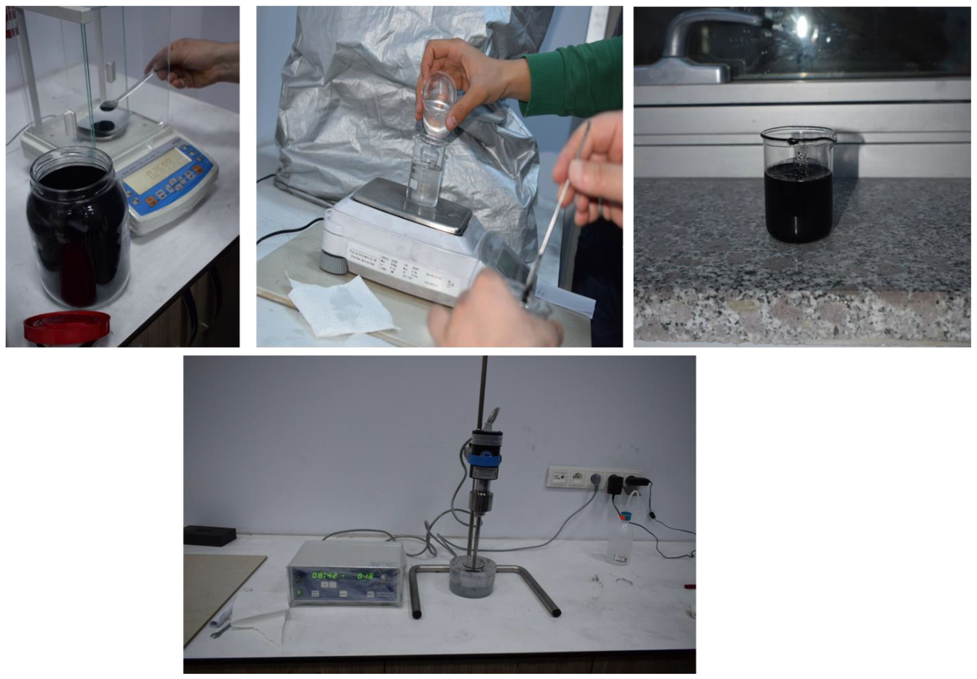
In order to manufacture composite material using the hand layup method, fabric layers were manually placed into the mold, and the epoxy resin was applied between each layer of the carbon fabric to completely coat the layer. By using a small roller, the air was trapped and evacuated. The process was performed at room temperature, and no curing process was carried out. By uniformly combining CNTs in epoxy resin and using the mixture of resin/CNT as the matrix of the composite, CNTRC was manufactured (
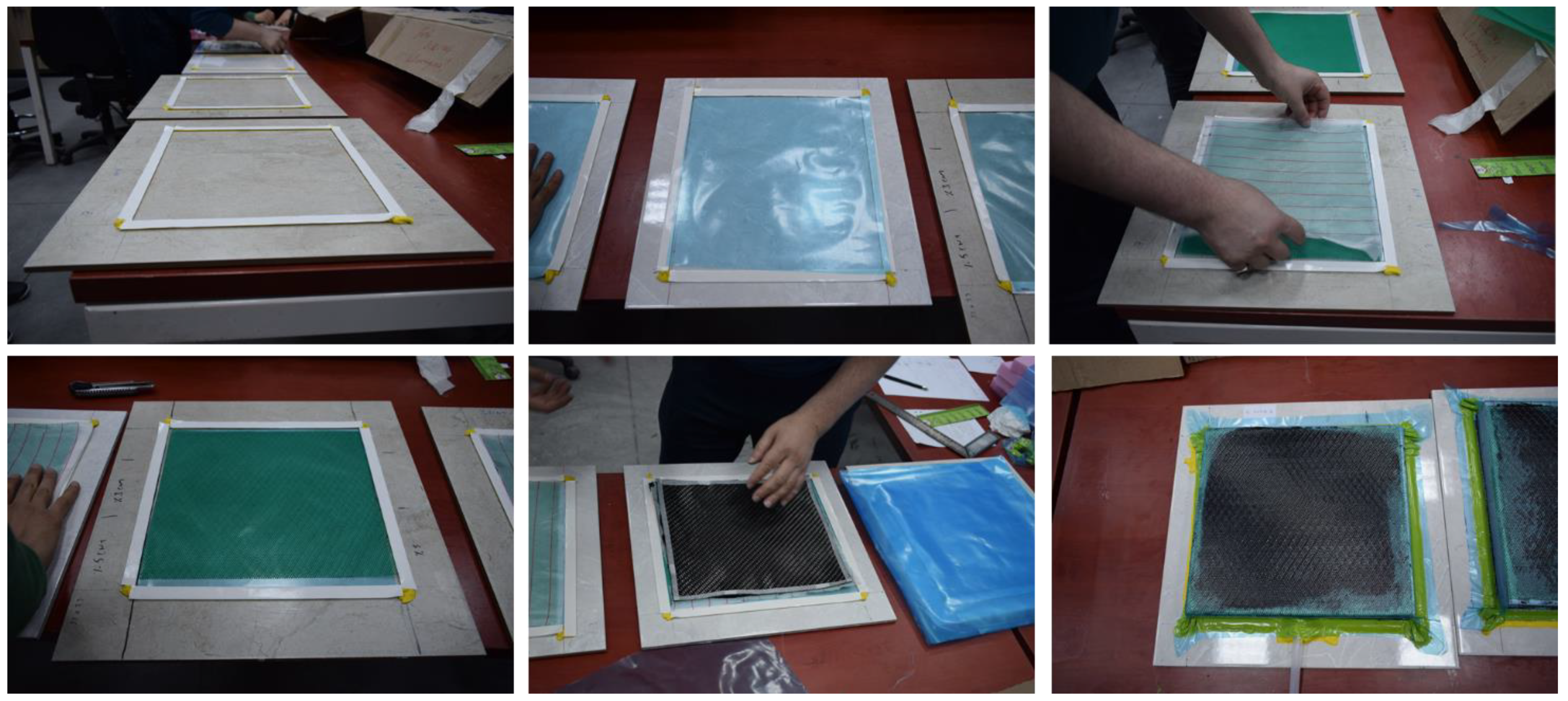
Figure 1). The industrial method is a production method that uses atmospheric pressure to compress resin-impregnated layers together. The equipment that was used included a vacuum pump, peel ply, sealant tape, bagging films, carbon fabric, epoxy resin and infusion mesh (Figure 2). After layup was finished, the peel ply was applied over the layers to create a clean surface, and, over the peel ply, a layer of infusion mesh was placed to assist the flow of resin across and throughout the laminate during the resin infusion process. Layers were sealed in an airtight vacuum bag, and epoxy resin was transferred by force of vacuum and passed through the fabric layers. Like the previous method, the process was performed at room temperature, and no curing was carried out. Some of the advantages of this method are that no air is trapped, and uniform resin distribution is achieved.
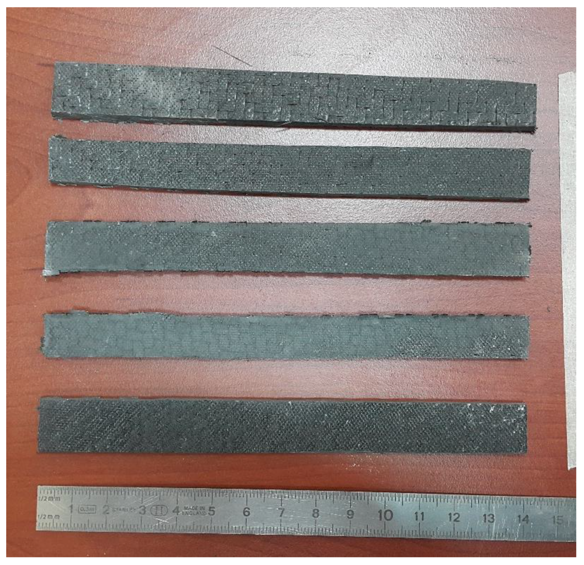
The composite material was manufactured by three layers of carbon fibers as well as resin epoxy (Figure 3).
The epoxy resin utilized in the manufacturing had a viscosity of 600–900 mPas and was two phase, with 80–90% diglycidyl ether bisphenol A, and it contained a mixture of 10–20% aliphatic diglycidyl ether. Multi-walled carbon nanotubes (MWCNTs) were preferred in the current study due to their low cost and homogeneous dispersibility in epoxy resins compared to MWCNTs. The mechanical properties of the MWCNTs were a diameter of 5–50 nm and a length of 10–30 µm. In this study, 200 gr carbon-fiber fabric produced from Tenax-E HTA 40 3k yarn in plain weave type was used. Carbon-fiber fabric (CFRP) is ideal for applications where lightness, strength and carbon are important. The mechanical properties obtained from the manufacturer of these materials are shown in Table 1.

3. Analytical Methods

3.1. Effective Properties of CNTRC

Young’s modulus, Poisson’s ratio and shear modulus are a few examples of the material parameters that need to be understood in order to predict the mechanical behavior of CNTRCs under buckling stress. In this section, the theoretical mixture rule model utilized to determine the properties of composites (CNT + epoxy) is defined as [50]:
E 11 e p o x y + C N T = η 1 V C N T E 11 C N T + V m E m
η 2 E 22 = V C N T E 22 C N T + V m E 22 m
η 3 G 12 = V C N T G 12 C N T + V m G m
ν 12 = V C N T ν 12 C N T + V m ν m
ρ = V C N T ρ C N T + V m ρ m
where E 11 C N T , E 22 C N T and G 12 C N T are Young’s and shear modulus of the single-walled CNT, respectively, and E m and G m represent the corresponding properties of the isotropic matrix. To account for the scale-dependent material properties, η i ( i = 1 , 2 , 3 ) is the CNT/matrix efficiency parameters which can be determined by matching the effective properties of the CNTRC observed from the molecular dynamics simulations with the predictions of the extended rule of mixture. ρ C N T and ρ m are the mass densities of the CNT and matrix, respectively. V C N T and V m are the volume fractions of the CNT and the matrix, respectively, and are related by:
V C N T + V m = 1
The mixture rule was developed for the mechanical properties of the fiber and matrix (CNT + epoxy) as follows [51]:
E 11 c o m p o s i t e = V f i b e r E 11 f i b e r + V m E m ( e p o x y + C N T )
ν 12 c o m p o s i t e = V f i b e r ν 12 f i b e r + V m ν m e p o x y + C N T

3.2. Governing Equations of CNTRC

The displacement field consisting of the axial displacement u and the transverse displacement w based on the Timoshenko beam theory of the forms are [52,53,54]:
u ( x , z , t ) = u 0 ( x , t ) + z ϕ x ( x , t ) v ( x , z , t ) = 0 w ( x , z , t ) = w 0 ( x , t )
where u 0 and w 0 are the axial and transverse displacements in the mid plane (z = 0) of the beam, respectively. ϕ x is the mid-plane rotation of the transverse normal about the y-axis.
The strain–displacement relations can be evaluated as:
ε x x = u 0 x + z ϕ x x γ x z = w 0 x + ϕ x
Hamilton’s principle can be written as [55]:
t 1 t 2 ( δ U + δ V δ K ) d t = 0
where K denotes the kinetic energy given by [56]:
δ K = 0 L A ρ ( z ) [ u δ u + w δ w ] d A d x = 0 L [ I 0 ( u 0 δ u 0 + w 0 δ w 0 ) + I 1 ( ϕ x δ u 0 + u 0 δ ϕ x ) + I 2 ϕ x δ ϕ x ] d x
in which Ii(i = 0, 1, 2) is the mass moment of inertia given by:
I i = A ρ ( z ) z i d A           ( i = 0 , 1 , 2 )
and δ U is the virtual variation of the total strain energy:
δ U = 0 L A ( Q 11 ε x x δ ε x x + Q 55 γ x z δ γ x z ) d A d x = 0 L ( N x d u 0 d x M x d δ ϕ x d x + Q x ( d δ w 0 d x δ ϕ x ) ) d x
and δ V is the virtual work performed by the transverse load q and axially compressive force N x 0 , represented as:
δ V = 0 L ( q δ w 0 + N x 0 w 0 x δ w 0 x ) d x
where the stress-related effects are as follows:
N x = A σ x x d A M x = A σ x x z d A Q z = A σ x z d A
The simplified stress–strain constitutive equations are given below:
σ x x = Q 11 ε x x σ x z = Q 55 γ x z
where
Q 11 = E 1 1 ϑ 12 ϑ 21 Q 55 = G 13
Substituting Equations (10) and (17) into Equation (16), the following is a list of all the stress resultants that may be expressed as material stiffness components and displacements:
ϕ x x = D 11 * M x w 0 x + ϕ x = 1 k s A 55 * Q x
where k s = 5 6 is the shear correction factor, and D 11 * and A 55 * are the elements of the inverse matrix of D 11 and A 55 .
D 11 = h 2 h 2 Q 11 z 2 d z = k = 1 N z k z k + 1 Q 11 ( k ) z 2 d z A 55 = h 2 h 2 Q 55 d z = k = 1 N z k z k + 1 Q 55 ( k ) d z
The following equations of motion are obtained for symmetrically laminated beams by using the integration-by-parts approach and gathering the coefficients of δ w 0 and δ φ x when the in-plane displacements u 0 are zero.
Q x x + N ^ x 0 2 w 0 x 2 + q = I 0 2 w 0 t 2 M x x Q x = I 2 2 ϕ x t 2
The equation of motion, Equation (21), may be expressed using Equation (19) in terms of displacements as:
k s G x z A ( 2 w 0 x 2 + ϕ x x ) + b N ^ x 0 2 w 0 x 2 + q ^ = I ^ 0 2 w 0 t 2 E x x I y y 2 ϕ x x 2 k s G x z A ( 2 w 0 x + ϕ x ) = I ^ 2 2 ϕ x t 2
To obtain the governing equation of buckling under compressive edge load, the inertia terms and applied transverse load q are both set to zero for the buckling analysis, and N ^ x 0 = N x x 0 .
k s G x z A ( d 2 W d x 2 + d ϕ x d x ) + b N ^ x 0 d 2 W d x 2 = 0 E x x I y y d 2 ϕ x d x 2 k s G x z A ( d W d x + ϕ x ) = 0
Equation (23) can be solved for d ϕ x d x to obtain:
k s G x z A d ϕ x d x = ( k s G x z A b N ^ x 0 ) d 2 W d x 2
Integrating Equation (24) with respect to x and differentiating Equation (23) with respect to x, then substituting them for d ϕ x d x from Equation (24) obtains the result:
E x x I y y ( 1 b N x x 0 k s G x z A ) d 4 W d x 4 + b N x x 0 d 2 W d x 2 = 0
The general solution of Equation (25) is:
W ( x ) = c 1 sin λ x + c 2 cos λ x + c 3 x + c 4
where
b N x x 0 = λ 2 E x x I y y ( 1 + λ 2 E x x I y y k s G x z A )
where the boundary conditions of the beam may be used to derive the integration constants c1, c2, c3 and c4.

4. Experimental Program

Two different tests were applied in this study: compressive and buckling tests. Two different types of samples with 0% (neat epoxy) and wt 0.3% CNT were examined. For each type of sample, two repetitions were investigated to give more accurate results.

4.1. Tensile Test

In order to obtain the tensile strength of the samples, the samples with nominal dimensions of 250 mm × 25 mm × 3 mm (length x width x thickness) were tested under tensile forces using a universal testing machine with 10-ton capacity. The distance between the gages was 200 mm. The procedure given in ASTM D3039 was utilized. The forces were applied at the speed of 1 mm/min.

4.2. Compressive Test

In order to obtain the compressive strength of the samples, the samples with nominal dimensions length 150 mm, width 25 mm and thickness 3 mm were exposed to axial compression forces using a Shimadzu universal testing machine with a capacity of 10 tons. The distance between the gages was 40 mm. The procedure given in ASTM D695 was applied. The forces were applied at the speed of 1 mm/min. The test setup utilized in this study is presented in Figure 4.

4.3. Buckling Test

The samples were examined under compression loads to determine the buckling behavior of the samples. The nominal dimensions of the specimens were 250 mm × 25 mm × 3 mm. The samples were tested with the same test machine. Similar to the compression test, buckling tests were carried out with a load speed of 1 mm/min. Utilizing clamped–clamped and simple–simple boundary conditions, the buckling performance of the samples was examined. Claw spacings of 200 mm and 250 mm were chosen for the clamped–clamped and simple–simple boundary conditions, respectively. The tests setups for different boundary conditions are shown in Figure 5.

5. Results

The material properties of the samples produced using micro-mechanical models were determined analytically, and the outcomes are presented in Table 2 in comparison with the experimental findings.
For the buckling analysis of the samples, the analytical solutions based on Timoshenko theory were in good agreement with the buckling results of the samples obtained by experiments, as shown in Table 3 and Table 4.
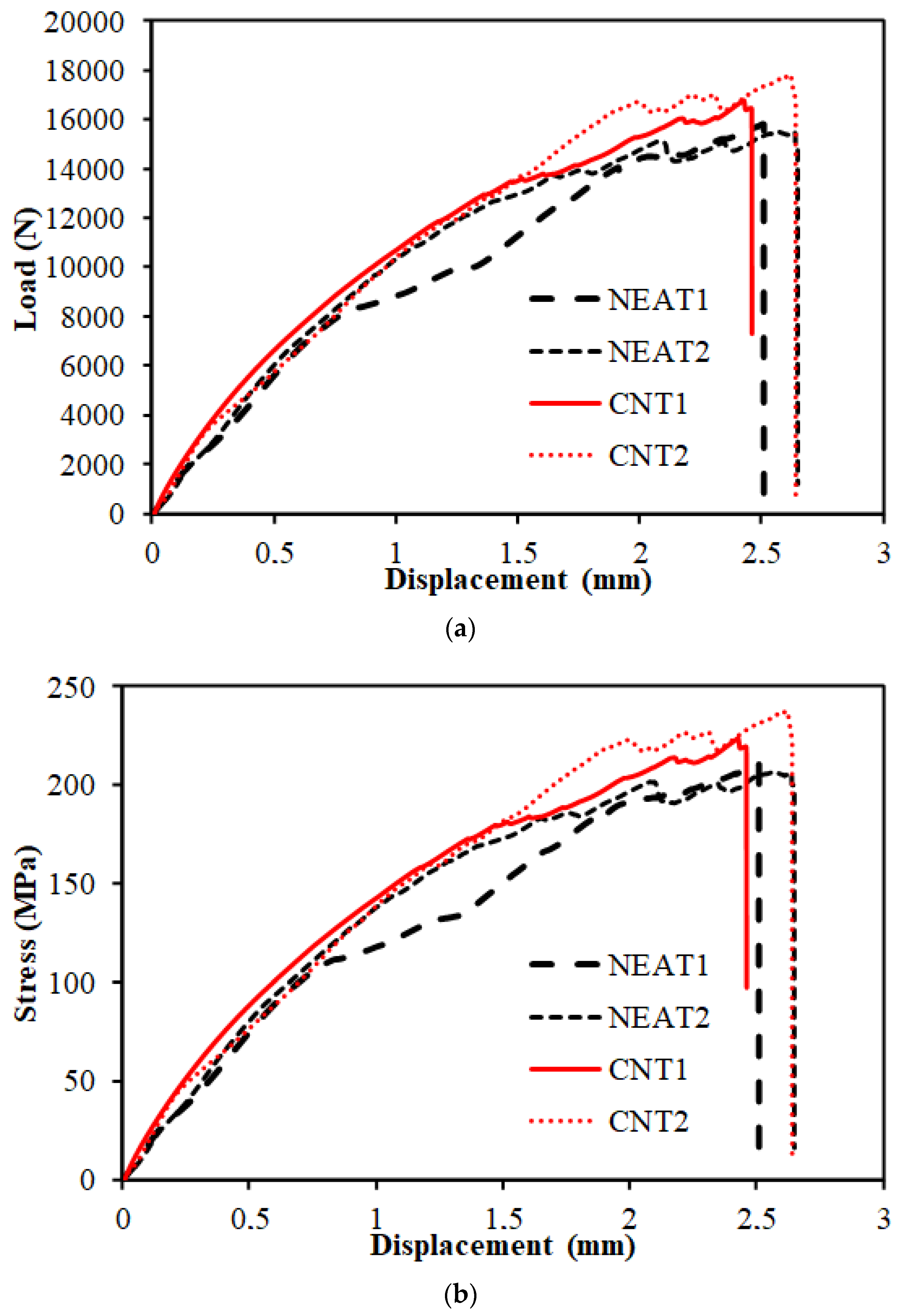
Load–displacement curves of the compression tests are depicted in Figure 6. The results demonstrate that the average compressive strength of CNT1 and CNT2 at the time of collapse was 17,291.76 N, while that of NEAT1 and NEAT2 was 15,661.21 N. Maximum compressive load values of CNT1 and CNT2 were 6% and 8.10% higher than those of NEAT1 and NEAT2, respectively, while CNT2 was 12.6% and 14.80% higher (Table 5). That is, it was determined that the samples with CNT carried an average of 10.4% more load than the samples with NEAT. All specimens reached the collapse position after approximately 2.5 mm of displacement. Another issue to be considered when comparing the samples with CNT and samples with NEAT is that the displacement amounts were the same under these loads. In other words, samples with CNT carried more load for the same displacement. In addition, the ratio of the maximum load value to the cross-sectional area of the sample (25 mm × 3 mm) and the stress values were also calculated (
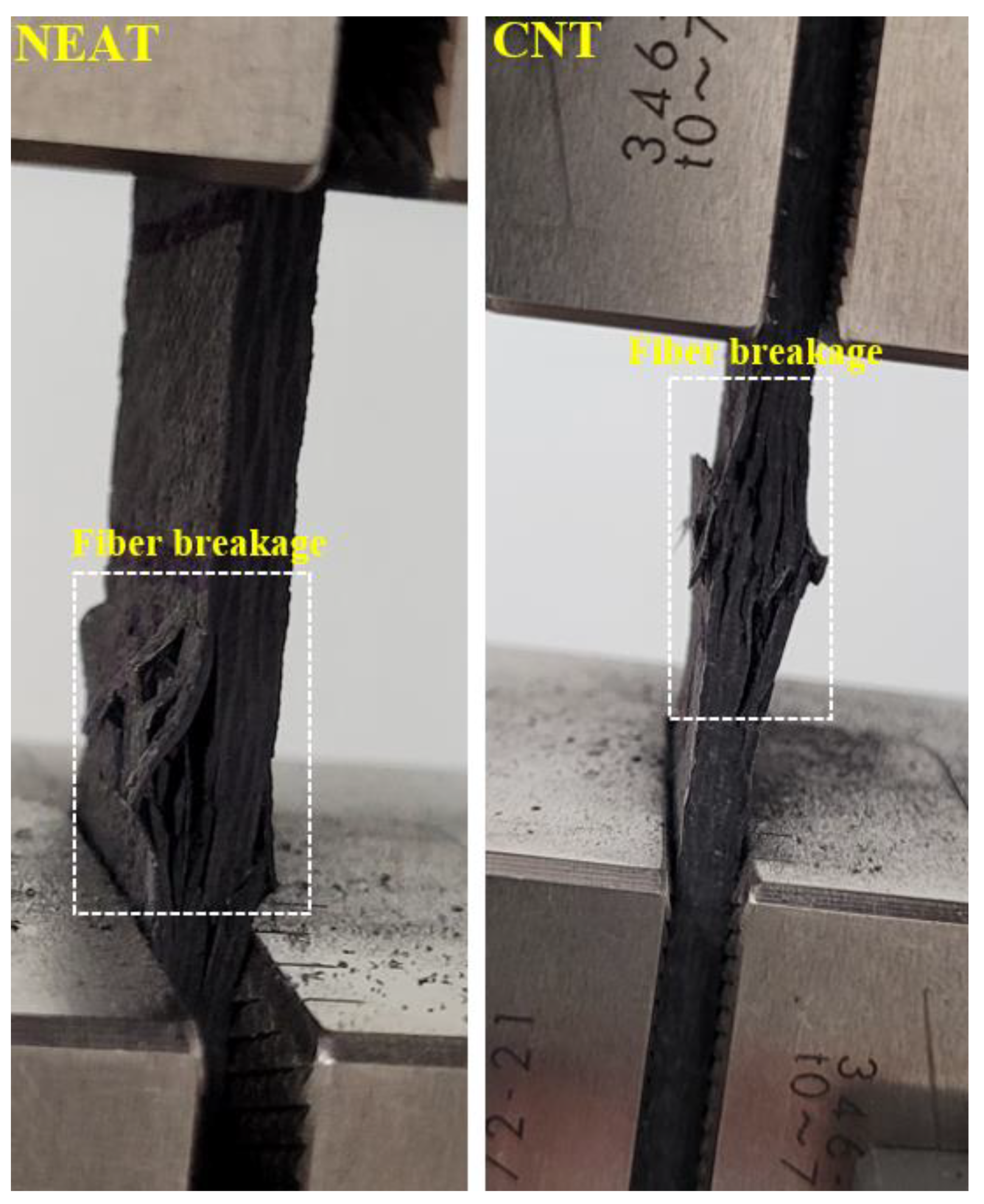
Figure 6). Damage formations in the samples occurred as shown in Figure 7. The experiment was terminated by observing fiber breakage damage as a result of typical pressure crushing. The initial stiffness values, that is, the angle of the curve with the horizontal, were higher in the CNT.
The buckling load–displacement plots of the specimens are shown in Figure 8 and Figure 9. The relationship for simple–simple is given in Figure 8, and the relationship for the clamped–clamped situation is given in
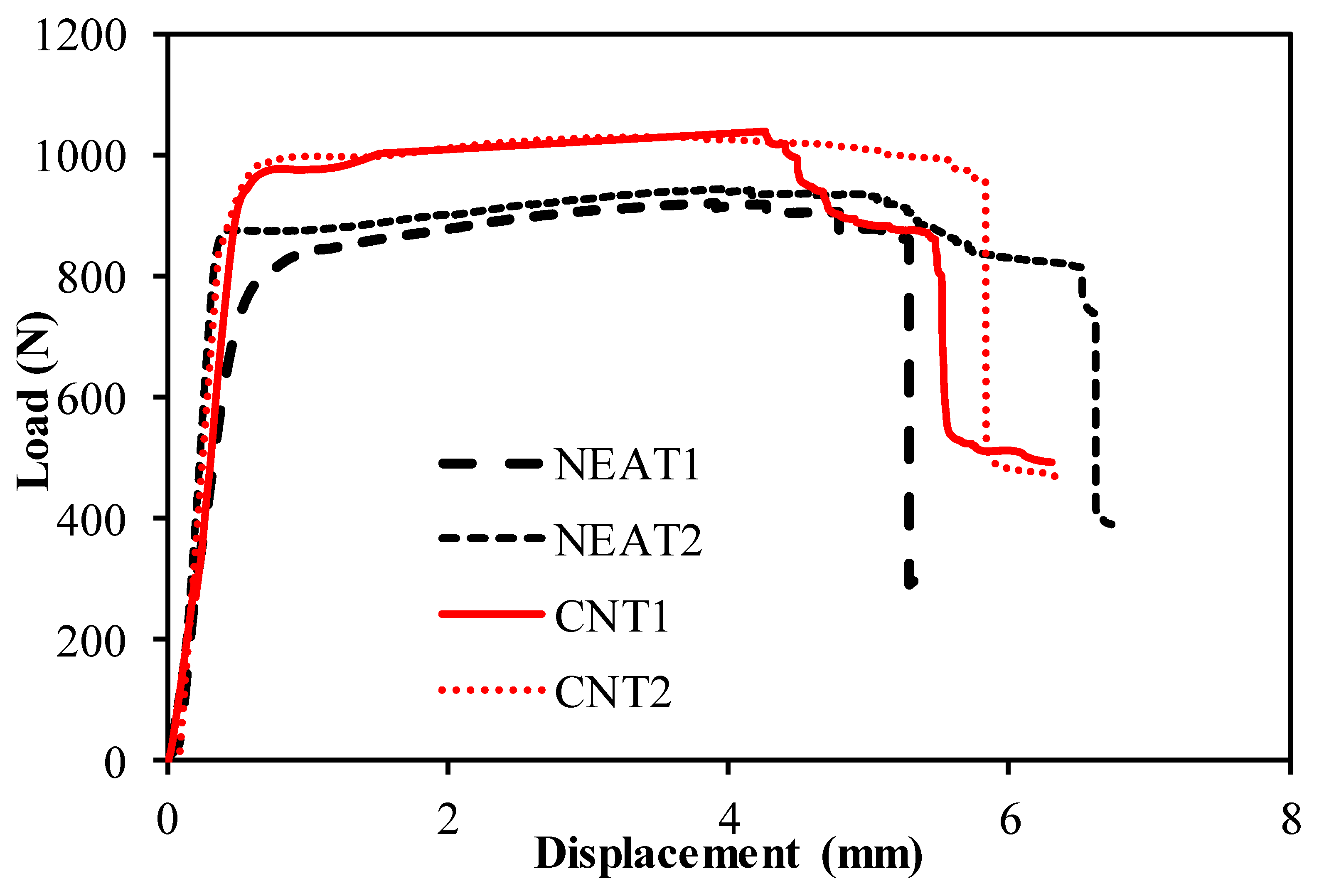
 Figure 9. When Figure 8 is examined, it can be seen that the mean buckling load value of CNT1 and CNT2 was 1036 N, while the mean buckling load value of NEAT1 and NEAT2 was 933 N. Maximum buckling load values of CNT1 and CNT2 were 12.8% and 10% higher than NEAT1 and NEAT2, respectively, while CNT2 was 11.8% and 9.1% higher (Table 6). In other words, samples with CNT carried a 11% greater buckling load on average than samples with NEAT. All specimens had vertical displacements between 5.48 mm and 6.73 mm due to buckling. This shows that the simple–simple supported CNT specimens achieved similar displacement with a higher buckling load. When 
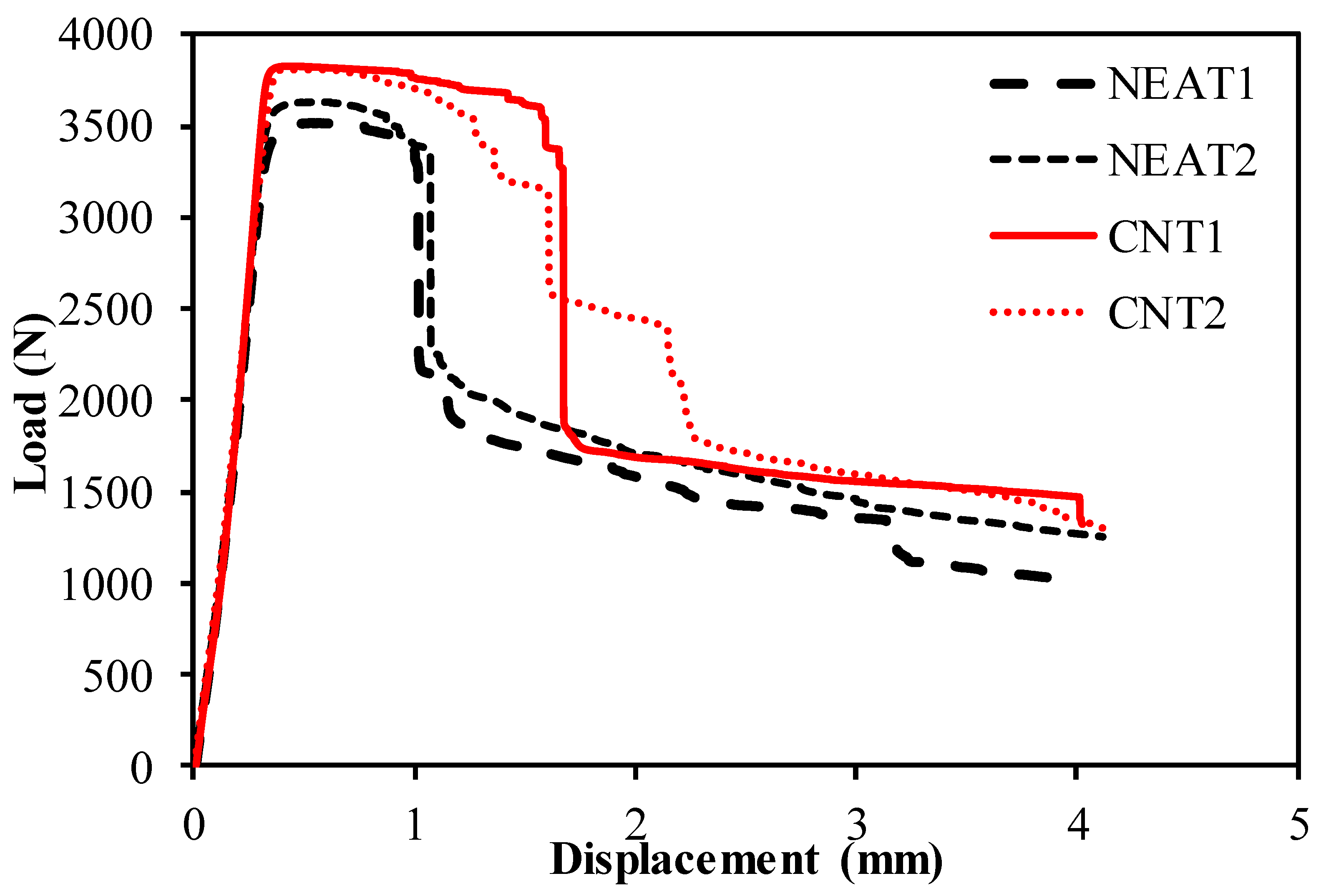
Figure 9 is examined, it can be seen that the mean buckling load value of CNT1 and CNT2 was 3817 N as a result of the buckling test, while it was calculated as 3572 N for NEAT1 and NEAT2. The average load-carrying capacity for the clamped–clamped boundary condition was 268% higher in the CNT samples and 282% higher in the NEAT samples compared to the simple–simple condition (Table 7). Up until the critical buckling threshold, the specimens showed a more rigid behavior as a result of the clamped–clamped boundary conditions.
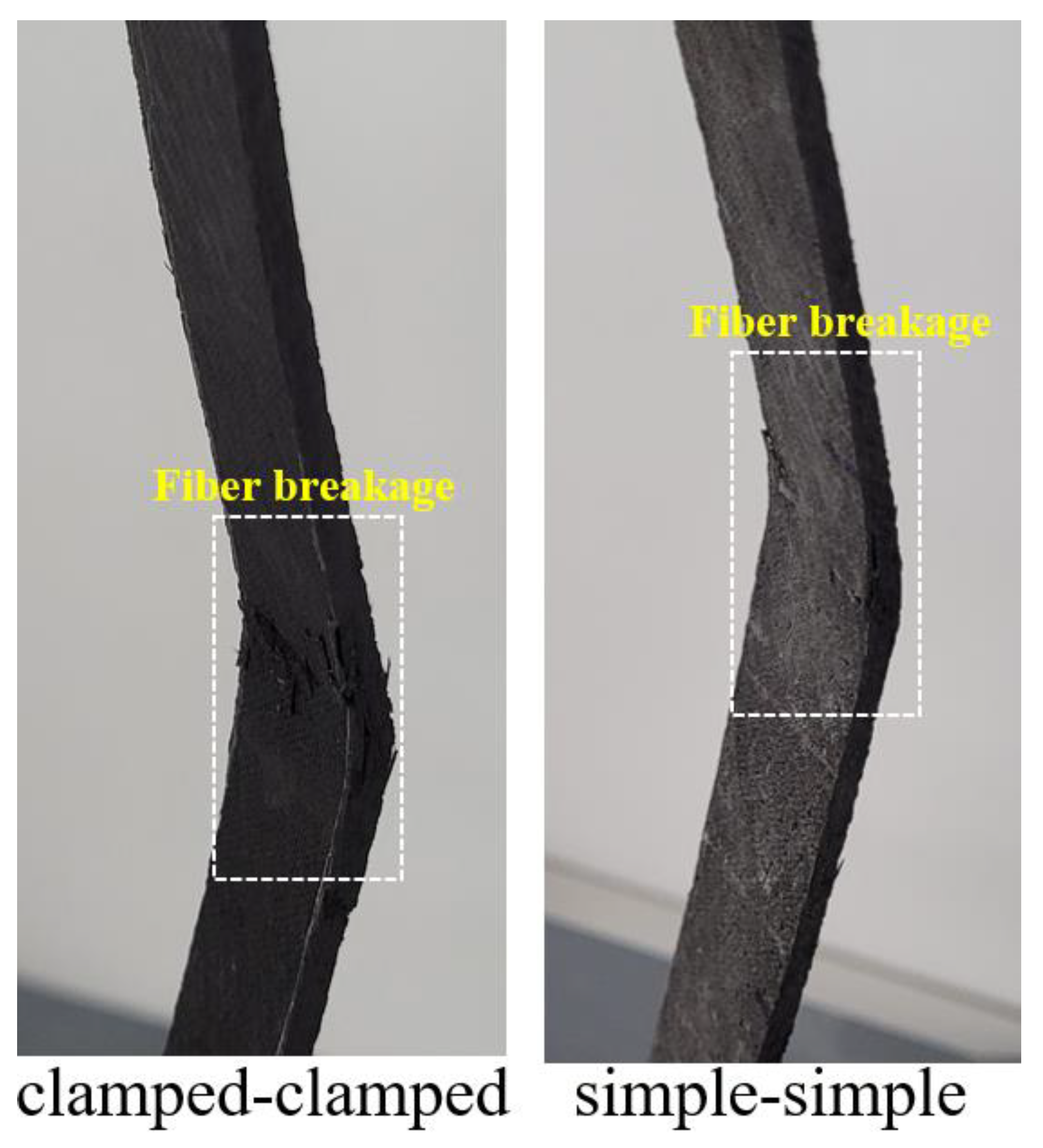
Final damage views on the samples are given in Figure 10. The final damage in both support boundary conditions was fiber breakage. However, this situation was observed more clearly in the clamped–clamped boundary condition.

6. Conclusions

In this paper, the impact of CNTs on the buckling analysis of CNTRC beams was analyzed analytically and experimentally. The mechanical behavior of composites was considerably altered by small CNT ratios. Considering the literature, significant improvements were obtained in the case of low CNT ratios.
  • The experimental outcomes indicated that adding CNT can improve a composite’s mechanical performance by up to 0.3%;
  • The developed analytical model and the previously presented experimental results exhibited great agreement;
  • The average load-carrying capacity for the clamped–clamped boundary condition was 268% higher in the CNT samples and 282% higher in the NEAT samples compared to the simple–simple condition. Therefore, the supporting conditions of the samples caused the capacity and load–displacement curves of buckling behavior to change;
  • The damage modes that occurred after compression and buckling were intense fiber breakage. In other words, in all buckling tests, it was observed that the damage initiated with micro cracks and showed progressive damage in the form of fiber rupture.
This study was limited to CNTRC beams and to the compression and elastic buckling behavior. In further research, many different types of laminates could be employed.

Author Contributions

Conceptualization, E.M. and Y.O.Ö.; Methodology, E.M., Y.O.Ö. and C.A.; Formal analysis, E.M. and Y.O.Ö.; Investigation, C.A. and A.S.; Writing—original draft, E.M., C.A., Y.O.Ö., M.R.M.A., A.S., A.B.M.S., N.M.; Writing—review & editing, E.M., C.A., Y.O.Ö., M.R.M.A., A.S., A.B.M.S., N.M. All authors have read and agreed to the published version of the manuscript.

Funding

The research was partially funded by the Ministry of Science and Higher Education of the Russian Federation as part of the World-Class Research Center program: Advanced Digital Technologies (contract No. 075-15-2022-312 dated 20 April 2022).

Institutional Review Board Statement

Not applicable.

Informed Consent Statement

Not applicable.

Data Availability Statement

Not applicable.

Conflicts of Interest

The authors declare no conflict of interest.

References

  1. Thostenson, E.T.; Ren, Z.; Chou, T.-W. Advances in the science and technology of carbon nanotubes and their composites: A review. Compos. Sci. Technol. 2001, 61, 1899–1912. [Google Scholar] [CrossRef] [Green Version]
  2. Wuite, J.; Adali, S. Deflection and stress behaviour of nanocomposite reinforced beams using a multiscale analysis. Compos. Struct. 2005, 71, 388–396. [Google Scholar] [CrossRef]
  3. Liew, K.; Lei, Z.; Zhang, L. Mechanical analysis of functionally graded carbon nanotube reinforced composites: A review. Compos. Struct. 2015, 120, 90–97. [Google Scholar] [CrossRef]
  4. Fidelus, J.; Wiesel, E.; Gojny, F.; Schulte, K.; Wagner, H. Thermo-mechanical properties of randomly oriented carbon/epoxy nanocomposites. Compos. Part A Appl. Sci. Manuf. 2005, 36, 1555–1561. [Google Scholar] [CrossRef]
  5. Kang, I.; Heung, Y.Y.; Kim, J.H.; Lee, J.W.; Gollapudi, R.; Subramaniam, S.; Narasimhadevara, S.; Hurd, D.; Kirikera, G.R.; Shanov, V.; et al. Introduction to carbon nanotube and nanofiber smart materials. Compos. Part B Eng. 2006, 37, 382–394. [Google Scholar] [CrossRef]
  6. Asyraf, M.R.M.; Khan, T.; Syamsir, A.; Supian, A.B.M. Synthetic and Natural Fiber-Reinforced Polymer Matrix Composites for Advanced Applications. Materials 2022, 15, 6030. [Google Scholar] [CrossRef]
  7. Amir, A.L.; Ishak, M.R.; Yidris, N.; Zuhri, M.Y.M.; Asyraf, M.R.M. Advances of composite cross arms with incorporation of material core structures: Manufacturability, recent progress and views. J. Mater. Res. Technol. 2021, 13, 1115–1131. [Google Scholar] [CrossRef]
  8. Madenci, E.; Özkılıç, Y.O.; Aksoylu, C.; Safonov, A. The effects of eccentric web openings on the compressive performance of pultruded GFRP boxes wrapped with GFRP and CFRP sheets. Polymers 2022, 14, 4567. [Google Scholar]
  9. Ozkilic, Y.O.; Gemi, L.; Madenci, E.; Aksoylu, C.; Kalkan, I. Effect of the GFRP wrapping on the shear and bending Behavior of RC beams with GFRP encasement. Steel Compos. Struct. 2022, 45, 193–204. [Google Scholar]
  10. Aksoylu, C.; Özkılıç, Y.O.; Madenci, E.; Safonov, A. Compressive behavior of pultruded GFRP boxes with concentric openings strengthened by different composite wrappings. Polymers 2022, 14, 4095. [Google Scholar] [CrossRef]
  11. Gemi, L.; Madenci, E.; Özkılıç, Y.O.; Yazman, Ş.; Safonov, A. Effect of Fiber Wrapping on Bending Behavior of Reinforced Concrete Filled Pultruded GFRP Composite Hybrid Beams. Polymers 2022, 14, 3740. [Google Scholar] [CrossRef] [PubMed]
  12. Gemi, L.; Alsdudi, M.; Aksoylu, C.; Yazman, Ş.; Özkılıç, Y.O.; Arslan, M.H. Optimum amount of CFRP for strengthening shear deficient reinforced concrete beams. Steel Compos. Struct. 2022, 43, 735–757. [Google Scholar]
  13. Vedernikov, A.N.; Safonov, A.A.; Gusev, S.A.; Carlone, P.; Tucci, F.; Akhatov, I.S. Spring-in Experimental Evaluation of L-shaped Pultruded Profiles, 1st ed.; IOP Publishing: Bristol, UK, 2020; p. 012013. [Google Scholar]
  14. Vedernikov, A.; Safonov, A.; Tucci, F.; Carlone, P.; Akhatov, I. Analysis of Spring-in Deformation in L-shaped Profiles Pultruded at Different Pulling Speeds: Mathematical Simulation and Experimental Results. 2021. Available online: https://popups.uliege.be/esaform21/index.php?id=4743 (accessed on 29 November 2022).
  15. Asyraf, M.R.M.; Syamsir, A.; Bathich, H.; Itam, Z.; Supian, A.B.M.; Norhisham, S.; Nurazzi, N.M.; Khan, T.; Rashid, M.Z.A. Effect of Fibre Layering Sequences on Flexural Creep Properties of Kenaf Fibre-reinforced Unsaturated Polyester Composite for Structural Applications. Fibers Polym. 2022, 23, 3232–3240. [Google Scholar] [CrossRef]
  16. Madenci, E.; Özkılıç, Y.O.; Gemi, L. Experimental and theoretical investigation on flexure performance of pultruded GFRP composite beams with damage analyses. Compos. Struct. 2020, 242, 112162. [Google Scholar] [CrossRef]
  17. Madenci, E.; Özkılıç, Y.O.; Gemi, L. Buckling and free vibration analyses of pultruded GFRP laminated composites: Experimental, numerical and analytical investigations. Compos. Struct. 2020, 254, 112806. [Google Scholar] [CrossRef]
  18. Madenci, E.; Özütok, A. Variational approximate for high order bending analysis of laminated composite plates. Struct. Eng. Mech. 2020, 73, 97–108. [Google Scholar]
  19. Madenci, E.; Özütok, A. Variational Approximate and Mixed-Finite Element Solution for Static Analysis of Laminated Composite Plates. In Solid State Phenomena; Trans Tech Publications Ltd.: Stafa-Zurich, Switzerland, 2017; pp. 35–39. [Google Scholar]
  20. Asyraf, M.R.M.; Syamsir, A.; Zahari, N.M.; Supian, A.B.M.; Usman, F.; Itam, Z. Effect of Stacking Sequence on Long-Term Creep Performance of Pultruded GFRP Composites. Polymers 2022, 14, 4064. [Google Scholar] [CrossRef]
  21. Syamsir, A.; Nadhirah, A.; Mohamad, D.; Beddu, S.; Asyraf, M.R.M.; Itam, Z.; Anggraini, V. Performance Analysis of Full Assembly Glass Fiber-Reinforced Polymer Composite Cross-Arm in Transmission Tower. Polymers 2022, 14, 1563. [Google Scholar] [CrossRef]
  22. Alhayek, A.; Syamsir, A.; Supian, A.B.M.; Usman, F.; Asyraf, M.R.M.; Atiqah, M.A. Flexural Creep Behaviour of Pultruded GFRP Composites Cross-Arm: A Comparative Study on the Effects of Stacking Sequence. Polymers 2022, 14, 1330. [Google Scholar] [CrossRef]
  23. Özkılıç, Y.O.; Yazman, Ş.; Aksoylu, C.; Arslan, M.H.; Gemi, L. Numerical investigation of the parameters influencing the behavior of dapped end prefabricated concrete purlins with and without CFRP strengthening. Constr. Build. Mater. 2021, 275, 122173. [Google Scholar] [CrossRef]
  24. Asyraf, M.R.M.; Ishak, M.R.; Norrrahim, M.N.F.; Amir, A.L.; Nurazzi, N.M.; Ilyas, R.A.; Asrofi, M.; Rafidah, M.; Razman, M.R. Potential of Flax Fiber Reinforced Biopolymer Composites for Cross-Arm Application in Transmission Tower: A Review. Fibers Polym. 2022, 23, 853–877. [Google Scholar] [CrossRef]
  25. Aksoylu, C.; Yazman, Ş.; Özkılıç, Y.O.; Gemi, L.; Arslan, M.H. Experimental analysis of reinforced concrete shear deficient beams with circular web openings strengthened by CFRP composite. Compos. Struct. 2020, 249, 112561. [Google Scholar] [CrossRef]
  26. Aksoylu, C.; Özkılıç, Y.O.; Yazman, Ş.; Gemi, L.; Arslan, M.H. Experimental and Numerical Investigation of Load Bearing Capacity of Thinned End Precast Purlin Beams and Solution Proposals. Teknik Dergi 2021. [Google Scholar] [CrossRef]
  27. Arslan, M.H.; Yazman, Ş.; Hamad, A.A.; Aksoylu, C.; Özkılıç, Y.O.; Gemi, L. Shear Strengthening of Reinforced Concrete T-beams with Anchored and Non-Anchored CFRP Fabrics; Elsevier: Amsterdam, The Netherlands, 2022; pp. 527–542. [Google Scholar]
  28. Tarfaoui, M.; El Moumen, A.; Boehle, M.; Shah, O.; Lafdi, K. Self-heating and deicing epoxy/glass fiber based carbon nanotubes buckypaper composite. J. Mater. Sci. 2019, 54, 1351–1362. [Google Scholar] [CrossRef]
  29. Apuzzo, A.; Barretta, R.; Luciano, R.; de Sciarra, F.M.; Penna, R. Free vibrations of Bernoulli-Euler nano-beams by the stress-driven nonlocal integral model. Compos. Part B Eng. 2017, 123, 105–111. [Google Scholar] [CrossRef]
  30. Ansari, R.; Torabi, J.; Shojaei, M.F. Buckling and vibration analysis of embedded functionally graded carbon nanotube-reinforced composite annular sector plates under thermal loading. Compos. Part B Eng. 2017, 109, 197–213. [Google Scholar] [CrossRef]
  31. Shahrbabaki, E.A.; Alibeigloo, A. Three-dimensional free vibration of carbon nanotube-reinforced composite plates with various boundary conditions using Ritz method. Compos. Struct. 2014, 111, 362–370. [Google Scholar] [CrossRef]
  32. Malekzadeh, P.; Zarei, A. Free vibration of quadrilateral laminated plates with carbon nanotube reinforced composite layers. Thin-Walled Struct. 2014, 82, 221–232. [Google Scholar] [CrossRef]
  33. Sankar, A.; Natarajan, S.; Ganapathi, M. Dynamic instability analysis of sandwich plates with CNT reinforced facesheets. Compos. Struct. 2016, 146, 187–200. [Google Scholar] [CrossRef]
  34. Wattanasakulpong, N.; Chaikittiratana, A. Exact solutions for static and dynamic analyses of carbon nanotube-reinforced composite plates with Pasternak elastic foundation. Appl. Math. Model. 2015, 39, 5459–5472. [Google Scholar] [CrossRef]
  35. Ahmadi, M.; Ansari, R.; Rouhi, H. Multi-scale bending, buckling and vibration analyses of carbon fiber/carbon nanotube-reinforced polymer nanocomposite plates with various shapes. Phys. E Low-Dimens. Syst. Nanostructures 2017, 93, 17–25. [Google Scholar] [CrossRef]
  36. Kiarasi, F.; Asadi, A.; Babaei, M.; Asemi, K.; Hosseini, M. Dynamic analysis of functionally graded carbon nanotube (FGCNT) reinforced composite beam resting on viscoelastic foundation subjected to impulsive loading. J. Comput. Appl. Mech. 2022, 53, 1–23. [Google Scholar]
  37. Babaei, M.; Asemi, K. Static, dynamic and natural frequency analyses of functionally graded carbon nanotube annular sector plates resting on viscoelastic foundation. SN Appl. Sci. 2020, 2, 1652. [Google Scholar] [CrossRef]
  38. Yas, M.H.; Samadi, N. Free vibrations and buckling analysis of carbon nanotube-reinforced composite Timoshenko beams on elastic foundation. Int. J. Press. Vessel. Pip. 2012, 98, 119–128. [Google Scholar] [CrossRef]
  39. Peigney, A.; Garcia, F.L.; Estournes, C.; Weibel, A.; Laurent, C. Toughening and hardening in double-walled carbon nanotube/nanostructured magnesia composites. Carbon 2010, 48, 1952–1960. [Google Scholar] [CrossRef]
  40. Zhan, G.-D.; Kuntz, J.D.; Wan, J.; Mukherjee, A.K. Single-wall carbon nanotubes as attractive toughening agents in alumina-based nanocomposites. Nat. Mater. 2003, 2, 38–42. [Google Scholar] [CrossRef] [PubMed]
  41. Shaffer, M.S.; Windle, A.H. Fabrication and characterization of carbon nanotube/poly (vinyl alcohol) composites. Adv. Mater. 1999, 11, 937–941. [Google Scholar] [CrossRef]
  42. Vodenitcharova, T.; Zhang, L.C. Bending and local buckling of a nanocomposite beam reinforced by a single-walled carbon nanotube. Int. J. Solids Struct. 2006, 43, 3006–3024. [Google Scholar] [CrossRef] [Green Version]
  43. Shahbaz, S. Investigation of the Effect of Carbon Nanotubes on Hybrid Glass/Carbon Fiber Reinforced Composites. 2016. Available online: https://polen.itu.edu.tr:8443/server/api/core/bitstreams/87656211-a822-49be-bb92-caa1c0f6390c/content (accessed on 27 June 2016).
  44. Madenci, E. Free vibration analysis of carbon nanotube RC nanobeams with variational approaches. Adv. Nano Res. 2021, 11, 157–171. [Google Scholar]
  45. Qian, D.; Wagner a Gregory, J.; Liu, W.K.; Yu, M.-F.; Ruoff, R.S. Mechanics of carbon nanotubes. Appl. Mech. Rev. 2002, 55, 495–533. [Google Scholar] [CrossRef]
  46. Zhu, J.; Peng, H.; Rodriguez-Macias, F.; Margrave, J.L.; Khabashesku, V.N.; Imam, A.M.; Lozano, K.; Barrera, E.V. Reinforcing epoxy polymer composites through covalent integration of functionalized nanotubes. Adv. Funct. Mater. 2004, 14, 643–648. [Google Scholar] [CrossRef]
  47. Tarfaoui, M.; Lafdi, K.; El Moumen, A. Mechanical properties of carbon nanotubes based polymer composites. Compos. Part B Eng. 2016, 103, 113–121. [Google Scholar] [CrossRef]
  48. Shivakumar Gouda, P.; Kulkarni, R.; Kurbet, S.; Jawali, D. Effects of multi walled carbon nanotubes and graphene on the mechanical properties of hybrid polymer composites. Adv. Mater. Lett. 2013, 4, 261–270. [Google Scholar] [CrossRef]
  49. Cedolin, L. Stability of Structures: Elastic, Inelastic, Fracture and Damage Theories; World Scientific: Singapore, 2010. [Google Scholar]
  50. Ebrahimi, F.; Rostami, P. Propagation of elastic waves in thermally affected embedded carbon-nanotube-reinforced composite beams via various shear deformation plate theories. Struct. Eng. Mech. 2018, 66, 495–504. [Google Scholar]
  51. Mohammadimehr, M.; Alimirzaei, S. Buckling and free vibration analysis of tapered FG-CNTRC micro Reddy beam under longitudinal magnetic field using FEM. Smart Struct. Syst. 2017, 19, 309–322. [Google Scholar] [CrossRef]
  52. Özütok, A.; Madenci, E. Free vibration analysis of cross-ply laminated composite beams by mixed finite element formulation. Int. J. Struct. Stab. Dyn. 2013, 13, 1250056. [Google Scholar] [CrossRef]
  53. Özütok, A.; Madenci, E.; Kadioglu, F. Free vibration analysis of angle-ply laminate composite beams by mixed finite element formulation using the Gâteaux differential. Sci. Eng. Compos. Mater. 2014, 21, 257–266. [Google Scholar] [CrossRef]
  54. Reddy, J.N. Mechanics of Laminated Composite Plates and Shells: Theory and Analysis; CRC Press: Boca Raton, FL, USA, 2004. [Google Scholar]
  55. Reddy, J.N. Energy Principles and Variational Methods in Applied Mechanics; John Wiley & Sons: Hoboken, NJ, USA, 2002. [Google Scholar]
  56. Wattanasakulpong, N.; Ungbhakorn, V. Analytical solutions for bending, buckling and vibration responses of carbon nanotube-reinforced composite beams resting on elastic foundation. Comput. Mater. Sci. 2013, 71, 201–208. [Google Scholar] [CrossRef]
Figure 1. CNTs in epoxy resin and using the mixture of resin/CNT as the matrix of the composite.
Materials 16 00614 g001
Figure 2. Manufacture of CNTRC composite material.
Materials 16 00614 g002
Figure 3. CNTRC composite samples.
Materials 16 00614 g003
Figure 4. Compression test setup.
Materials 16 00614 g004
Figure 5. Test setups depending on boundary conditions. (a) simple–simple; (b) clamped–clamped.
Materials 16 00614 g005
Figure 6. (a,b) Compression test results of the samples.
Materials 16 00614 g006
Figure 7. Macro damage in the samples.
Materials 16 00614 g007
Figure 8. Buckling test results of the samples with simple–simple.
Materials 16 00614 g008
Figure 9. Buckling test results of the samples with clamped–clamped.
Materials 16 00614 g009
Figure 10. Damage analysis of simple–simple and clamped–clamped supported samples.
Materials 16 00614 g010
Table 1. Material properties.
Carbon FiberEpoxy MatrixCNT
E11 (GPa)2302.72500
E22 (GPa)152.72500
E33 (GPa)152.72500
ʋ120.280.30.26
ʋ130.280.30.26
ʋ230.280.30.26
G12 (GPa)151.18
G13 (GPa)151.18
G23 (GPa)151.18
Table 2. Young’s modulus model results.
SampleYoung’s Moduli (GPa)
ExperimentalAnalytical
0.0%wt CNT12.1814.48
0.3%wt CNT13.4216.18
Table 3. Comparisons of critical loads for simple–simple CNTRC beams.
0%0.3%
Experimental9331036
Analytical9471102
Table 4. Comparisons of critical loads for clamped–clamped CNTRC beams.
0%0.3%
Experimental35723817
Analytical35933899
Table 5. The maximum compression load and displacements of samples.
SampleMaximum Load (N)Rate of Increase (%)Maximum Displacement (mm)
NEAT115,816.182.51
NEAT215,506.252.65
CNT116,771.166 and 8.102.46
CNT217,812.3612.10 and 14.802.64
Table 6. The buckling load and vertical displacements of simple–simple supported samples.
SampleMaximum Load (N)Rate of Increase (%)Maximum Displacement (mm)
NEAT1922.205.48
NEAT2945.286.73
CNT11040.4412.8 and 106.30
CNT21031.6811.8 and 9.16.35
Table 7. The buckling load and vertical displacements of clamped–clamped supported samples.
SampleMaximum Load (N)Rate of Increase (%)Maximum Displacement (mm)
NEAT13516.023.88
NEAT23629.424.11
CNT13825.808.8 and 5.44.02
CNT23808.218.3 and 4.94.13
Disclaimer/Publisher’s Note: The statements, opinions and data contained in all publications are solely those of the individual author(s) and contributor(s) and not of MDPI and/or the editor(s). MDPI and/or the editor(s) disclaim responsibility for any injury to people or property resulting from any ideas, methods, instructions or products referred to in the content.

