
Composite Lamina Model Design with the Use of Heuristic Optimization


Abstract
1. Introduction
1.1. An Observed Case Definition
1.2. Assumptions
2. Materials and Methods
2.1. Failure Criteria of Strength and Buckling
2.2. Strength Failure Criterion
- Determination of the coefficients of the layered stiffness of the package B:where and are adduced Young’s modulus. E1, E2, and G12 are Young’s modulus along and transverse fiber, and Shear modulus. µ12 is normal Poisson’s ratio, µ21 is transverse Poisson’s ratio, and δi is the thickness of layer i:
- Determination of deformations of a package of layers in the general (global) coordinate system of the entire package (Equation (7)):where Nx is the longitudinal force in the skin plane, Ny is the transverse force, qxy is the tangential force flow, and B11 (12, 22, 33) are the stiffness coefficients.
- Determination of deformations of each layer in its own (local) coordinate system (Equations (8)–(10)):
- Knowing the elastic characteristics of each layer from its deformations, it is possible to determine the loads (Equations (11)–(13)) that are acting in the layer according to the physical law:
2.3. Strenght Buckling Failure Criterion
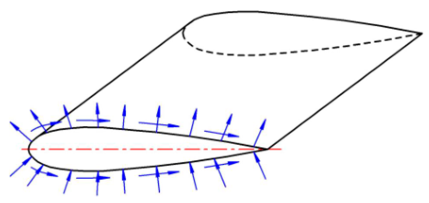
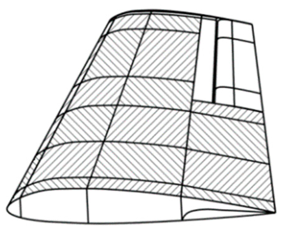
2.4. Case Study
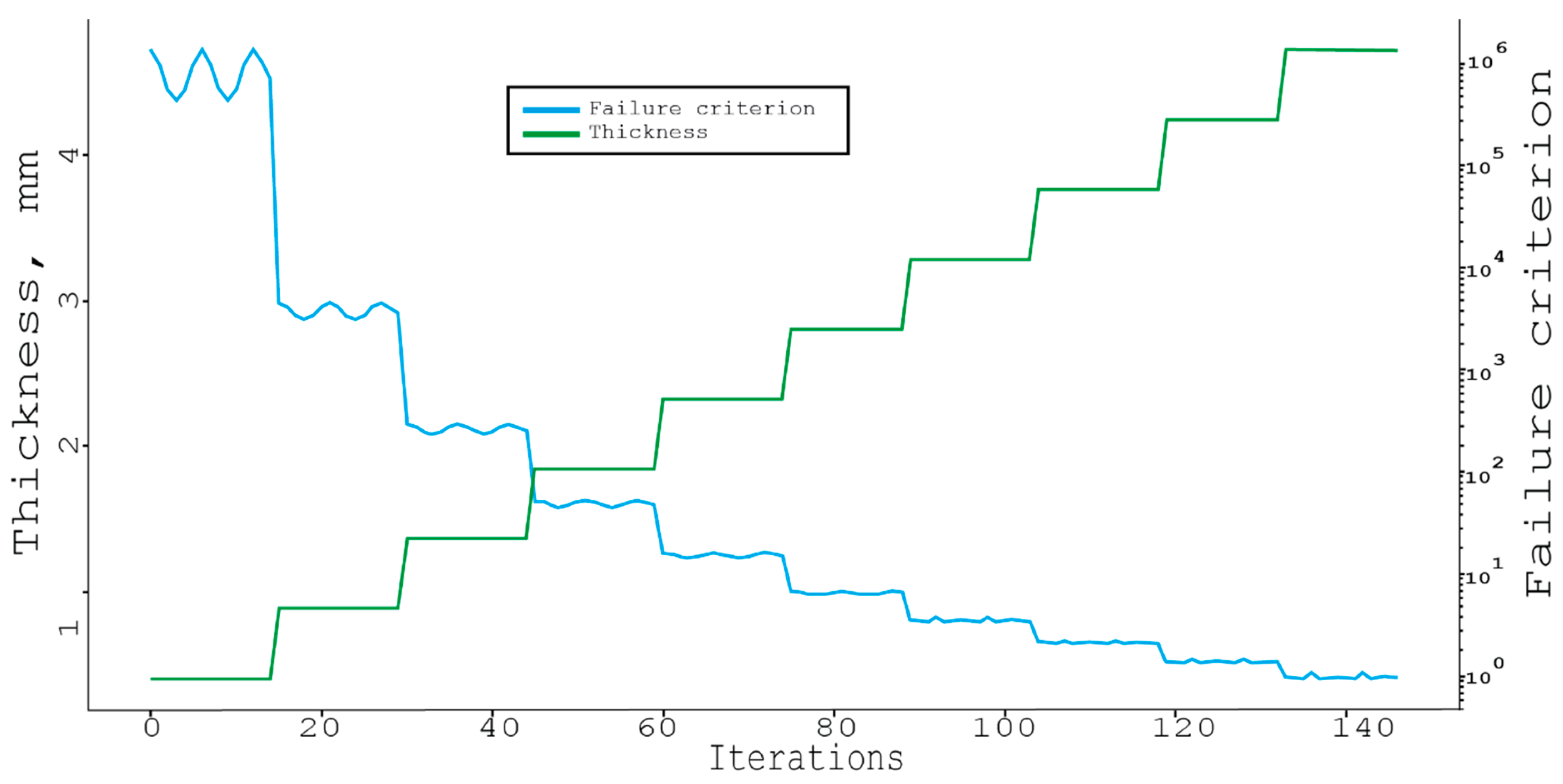
3. Results
Greedy Neighborhood
4. Conclusions
Author Contributions
Funding
Institutional Review Board Statement
Informed Consent Statement
Data Availability Statement
Acknowledgments
Conflicts of Interest
References
- Hrehova, S.; Knapcikova, L. The Study of Machine Learning Assisted the Design of Selected Composites Properties. Appl. Sci. 2022, 12, 10863. [Google Scholar] [CrossRef]
- Mascenik, J.; Coranic, T. Experimental Determination of the Coefficient of Friction on a Screw Joint. Appl. Sci. 2022, 12, 11987. [Google Scholar] [CrossRef]
- Relich, M.; Nielsen, I.; Gola, A. Reducing the Total Product Cost at the Product Design Stage. Appl. Sci. 2022, 12, 1921. [Google Scholar] [CrossRef]
- Marler, R.T.; Arora, J.S. Survey of multi-objective optimization methods for engineering. Struct. Multidiscip. Optim. 2004, 26, 369–395. [Google Scholar] [CrossRef]
- Noor, A.K.; Burton, W.S.; Bert, C.W. Computational Models for Sandwich Panels and Shells. Appl. Mech. Rev. 1996, 49, 155–199. [Google Scholar] [CrossRef]
- Wu, Y.; Weaver, P.B.; Raju, G.; Kim, B.C. Buckling analysis and optimisation of variable angle tow composite plates. Thin-Wallet Struct. 2012, 60, 163–172. [Google Scholar] [CrossRef]
- Jurecyko, M.; Pawlak, M.; Mezyk, A. Optimisation of wind turbine blades. J. Mater. Process. Technol. 2005, 167, 463–471. [Google Scholar] [CrossRef]
- Stachová, K.; Stacho, Z.; Cagáňová, D.; Stareček, A. Use of Digital Technologies for Intensifying Knowledge Sharing. Appl. Sci. 2020, 10, 4281. [Google Scholar] [CrossRef]
- Hamrol, A.; Ciszak, O.; Legutko, S.; Jurczyk, M. Advances in Manufacturing; Springer: Cham, Switzerland, 2017; p. 965. [Google Scholar] [CrossRef]
- Zhao, Z.; Song, W.; Jin, Y.; Lu, J. Effect of Rotational Speed Variation on the Flow Characteristics in the Rotor-Stator System Cavity. Appl. Sci. 2021, 11, 11000. [Google Scholar] [CrossRef]
- Pozorski, Z.; Wojciechowski, S. The Influence of Symmetrical Boundary Conditions on the Structural Behaviour of Sandwich Panels Subjected to Torsion. Symmetry 2020, 12, 2093. [Google Scholar] [CrossRef]
- Ivanov, V.; Botko, F.; Kolos, V.; Pavlenko, I.; Hatala, M.; Antosz, K.; Trojanowska, J. Locating Chart Choice Based on the Decision-Making Approach. Materials 2022, 15, 3557. [Google Scholar] [CrossRef] [PubMed]
- Pavlenko, I.; Piteľ, J.; Ivanov, V.; Berladir, K.; Mižáková, J.; Kolos, V.; Trojanowska, J. Using Regression Analysis for Automated Material Selection in Smart Manufacturing. Mathematics 2022, 10, 1888. [Google Scholar] [CrossRef]
- Antosz, K.; Machado, J.; Mazurkiewicz, D.; Antonelli, D.; Soares, F. Systems Engineering: Availability and Reliability. Appl. Sci. 2022, 12, 2504. [Google Scholar] [CrossRef]
- Gagauz, P.; Gagauz, F.; Karpov, J. Design and Construction from Composite Materials. Theory and Practice; National Aerospace University: Kharkiv, Ukraine, 2015; p. 672. [Google Scholar]
- Karpov, J. Design of Parts and Structures from Composite Materials; National Aviation University: Kharkiv, Ukraine, 2010. [Google Scholar]
- Grima-Cornish, J.N.; Vella-Żarb, L.; Grima, J.N.; Evans, K.E. A DFT-Based Quantitative and Geometric Analysis of the Effect of Pressure on Boron Arsenate. Materials 2022, 15, 4858. [Google Scholar] [CrossRef]
- Antosz, K.; Pasko, L.; Gola, A. The Use of Artificial Intelligence Methods to Assess the Effectiveness of Lean Maintenance Concept Implementation in Manufacturing Enterprises. Appl. Sci. 2020, 10, 7922. [Google Scholar] [CrossRef]
- Knapcikova, L.; Husar, J.; Herzog, M.; Pesek, L. Testing of new composite materials based on fabric from used tires. Chem. Listy 2012, 106, 450–452. [Google Scholar]
- Behun, M.; Kascak, P.; Hrabcak, M.; Behunova, A.; Knapcikova, L.; Sofranko, M. Investigation of Sustainable Geopolymer Composite Using Automatic Identification Technology. Sustainability 2020, 12, 6377. [Google Scholar] [CrossRef]
- Kaščak, J.; Gašpár, Š.; Paško, J.; Husár, J.; Knapčíková, L. Polylactic Acid and Its Cellulose Based Composite as a Significant Tool for the Production of Optimized Models Modified for Additive Manufacturing. Sustainability 2021, 13, 1256. [Google Scholar] [CrossRef]
- Kunene, T.J.; Tartibu, L.K.; Karimzadeh, S.; Oviroh, P.O.; Ukoba, K.; Jen, T.-C. Molecular Dynamics of Atomic Layer Deposition: Sticking Coefficient Investigation. Appl. Sci. 2022, 12, 2188. [Google Scholar] [CrossRef]
- Dreo, J.; Petrowski, A.; Siarry, P.; Taillard, E. Methaheuristics for Hard Optimization: Methods and Case Studies; Springer–Verl.: Berlin/Heidelberg, Germany, 2005; p. 369. [Google Scholar]
- Hopper, E.; Turton, B.C.H. An empirical investigation of metaheuristic and heuristic algorithms for a 2D packing problem. Europ. J. Oper. Res. 2001, 128, 34–57. [Google Scholar] [CrossRef]
- Huang, W.Q.; Li, Y.; Akeb, H.; Li, C.M. Greedy algorithms for packing unequal circles into a rectangular container. J. Oper. Res. Soc. 2005, 56, 539–548. [Google Scholar] [CrossRef]
- Relich, M.; Bocewicz, G.; Banaszak, Z. Cost Projections for the Product Life Cycle at the Early Stages of Product Development. In Advances in Production Management Systems. Artificial Intelligence for Sustainable and Resilient Production Systems. APMS 2021; IFIP Advances in Information and Communication Technology; Springer: Cham, Switzerland, 2021; p. 633. [Google Scholar] [CrossRef]
- Musiał, K.; Balashov, A.; Burduk, A.; Batako, A.; Safonyk, A. Solving Scheduling Problems in Case of Multi-objective Production Using Heuristic Optimization. In Advances in Manufacturing III. MANUFACTURING 2022. Lecture Notes in Mechanical Engineering; Springer: Cham, Switzerland, 2022. [Google Scholar] [CrossRef]
- Glover, F.; Laguna, M. Tabu Search; Kluwer Academic Publishers: Dordrecht, The Netherlands, 1997; p. 382. [Google Scholar]
- Coranic, T.; Gaspar, S.; Pasko, J. Utilization of Optimization of Internal Topology in Manufacturing of Injection Moulds by the DMLS Technology. Appl. Sci. 2021, 11, 262. [Google Scholar] [CrossRef]
- Hrehova, S. Predictive model to evaluation quality of the manufacturing process using Matlab tools. Procedia Eng. 2016, 149, 149–154. [Google Scholar] [CrossRef][Green Version]
- Musiał, K.; Kotowska, J.; Górnicka, D.; Burduk, A. Tabu Search and Greedy Algorithm Adaptation to Logistic Task. In Computer Information Systems and Industrial Management; Springer International Publishing: Berlin/Heidelberg, Germany, 2017. [Google Scholar] [CrossRef]
- Karpov, J. Design and Technological Solutions for Panels of Composite Materials; National Aviation University: Kharkiv, Ukraine, 2010. [Google Scholar]
- Majernik, J.; Gaspar, S.; Kmec, J.; Karkova, M.; Mascenik, J. Possibility of Utilization of Gate Geometry to Modify the Mechanical and Structural Properties of Castings on the Al-Si Basis. Materials 2020, 13, 3539. [Google Scholar] [CrossRef] [PubMed]


| Load Direction | Case 1 | Case 2 | Case 3 |
|---|---|---|---|
| Nx | −600 | 0 | −300 |
| Ny | 0 | −500 | −400 |
| qxy | 50 | 0 | 100 |
| No | 1 | 2 | 3 | 4 | 5 | 6 | 7 | 8 | 9 |
|---|---|---|---|---|---|---|---|---|---|
| Type | Carbon | Organic | |||||||
| Fiber | AS4, 63% | IM6, 65% | ModI, 45% | GY70, 57% | AS4, 58% | AGP 3705 5H, 62% | CF 0604, 55% | Kevlar 49, 60% | K120, 45% |
| Matrix | epoxy 3501-6 | epoxy sc1081 | WRD 9371 | epoxy 934 | PEEK APC2 | epoxy 3501-6 | epoxy 934 | epoxy M10.2 | epoxy M10.2 |
| E1, GPa | 147 | 177 | 216 | 294 | 131 | 77 | 65.6 | 80 | 29 |
| E2, GPa | 10.3 | 10.8 | 5 | 6.4 | 8.7 | 75 | 60.3 | 5.5 | 29 |
| G12, GPa | 7 | 7.6 | 4.5 | 4.9 | 5 | 6.5 | 3.98 | 2.2 | 1.8 |
| µ12 | 0.27 | 0.27 | 0.25 | 0.23 | 0.28 | 0.06 | 0.04 | 0.34 | 0.05 |
| F1t, MPa | 2280 | 2860 | 807 | 589 | 2060 | 963 | 927 | 1400 | 369 |
| F1c, MPa | 1725 | 1875 | 665 | 491 | 1080 | 900 | 729 | 335 | 129 |
| F2t, MPa | 57 | 49 | 15 | 29.4 | 78 | 856 | 874 | 30 | 369 |
| F2c, MPa | 228 | 246 | 71 | 98.1 | 196 | 900 | 620 | 158 | 129 |
| F12, MPa | 76 | 83 | 22 | 49.1 | 157 | 71 | 133 | 49 | 113 |
| ρ, kg/m3 | 1580 | 1600 | 1540 | 1590 | 1570 | 1600 | 1560 | 1380 | 1380 |
| δ0, mm | 0.12 | 0.15 | 0.16 | 0.1 | 0.15 | 0.42 | 0.3 | 0.15 | 0.22 |
| No | Loads | ||||
|---|---|---|---|---|---|
| 1 | 65, −255, −670 | 0, 0, 780 | −335, −245, 195 | −465, −525, 115 | 265, 0, 0 |
| 2 | 0, 665, 605 | -150, 0, 475 | 0, -800, −425 | 0, −670, 0 | 0, 415, −650 |
| 3 | −355, 730, −770 | −330, −740, −695 | 0, 0, 0 | −600, −275, 775 | −640, 385, 525 |
| 4 | −730, 0, 485 | 70, 600, 710 | 0, 205, 0 | 430, −200, 0 | 620, 665, 585 |
| 5 | −335, 735, −630 | −605, −690, −645 | 0, 250, 0 | 0, 0, −145 | 0, −60, 755 |
| 6 | 780, −10, 0 | 755, 0, 215 | −460, −775, 0 | 315, −710, −510 | 0, 0, −180 |
| 7 | 0, 460, 135 | 0, 0, 480 | 25, 0, 0 | 0, 755, 245 | 0, 0, −745 |
| 8 | 0, 0, 360 | 580, 430, −225 | 485, 0, 635 | −325, 500, 0 | −295, 575, −570 |
| 9 | 0, −665, 550 | −740, −770, 0 | 705, 710, 0 | 0, −575, −35 | 640, 0, 0 |
| 10 | 410, 115, 55 | 0, 0, −15 | −450, 0, 0 | 170, −485, −245 | 0, −195, 0 |
| No | Analytic | Full Greedy | Local Greedy | Tabu Search |
|---|---|---|---|---|
| 1 | 9.53 / 4.1 | 0.96 / 5.52 / 942 | 0.85 / 5.28 / 64 | 0.84 / 5.28 / 158 |
| 2 | 8.91 / 3.4 | 0.98 / 6.08 / 1271 | 0.92 / 5.04 / 47 | 0.8 / 5.28 / 154 |
| 3 | 11.08 / 4.8 | 0.96 / 8.48 / 3271 | 0.99 / 6.0 / 73 | 0.97 / 5.76 / 205 |
| 4 | 10.82 / 2.9 | 1.13 / 6.68 / 1656 | 0.97 / 8.16 / 131 | 0.76 / 5.76 / 199 |
| 5 | 12.21 / 3.9 | 1.04 / 7.28 / 2116 | 0.87 / 5.88 / 82 | 0.73 / 6.24 / 256 |
| 6 | 12.01 / 3.4 | 0.96 / 6.64 / 1649 | 0.74 / 8.16 / 220 | 0.99 / 7.2 / 375 |
| 7 | 6.68 / 2.7 | 0.97 / 5.48 / 938 | 0.69 / 3.96 / 24 | 0.78 / 3.84 / 65 |
| 8 | 6.07 / 2.7 | 0.94 / 6.68 / 1654 | 0.98 / 12.96 / 442 | 1.0 / 5.28 / 145 |
| 9 | 12.84 / 3.8 | 1.09 / 6.08 / 1270 | 0.93 / 7.68 / 174 | 0.74 / 7.2 / 379 |
| 10 | 8.6 / 3.1 | 0.73 / 4.24 / 473 | 0.95 / 4.92 / 41 | 0.98 / 4.32 / 87.4 |
Disclaimer/Publisher’s Note: The statements, opinions and data contained in all publications are solely those of the individual author(s) and contributor(s) and not of MDPI and/or the editor(s). MDPI and/or the editor(s) disclaim responsibility for any injury to people or property resulting from any ideas, methods, instructions or products referred to in the content. |
© 2023 by the authors. Licensee MDPI, Basel, Switzerland. This article is an open access article distributed under the terms and conditions of the Creative Commons Attribution (CC BY) license (https://creativecommons.org/licenses/by/4.0/).
Share and Cite
Balashov, A.; Burduk, A.; Husár, J. Composite Lamina Model Design with the Use of Heuristic Optimization. Materials 2023, 16, 495. https://doi.org/10.3390/ma16020495
Balashov A, Burduk A, Husár J. Composite Lamina Model Design with the Use of Heuristic Optimization. Materials. 2023; 16(2):495. https://doi.org/10.3390/ma16020495
Chicago/Turabian StyleBalashov, Artem, Anna Burduk, and Jozef Husár. 2023. "Composite Lamina Model Design with the Use of Heuristic Optimization" Materials 16, no. 2: 495. https://doi.org/10.3390/ma16020495
APA StyleBalashov, A., Burduk, A., & Husár, J. (2023). Composite Lamina Model Design with the Use of Heuristic Optimization. Materials, 16(2), 495. https://doi.org/10.3390/ma16020495