


Comparison of CrN Coatings Prepared Using High-Power Impulse Magnetron Sputtering and Direct Current Magnetron Sputtering


Abstract
:1. Introduction
2. Plasma-Based Depositions
2.1. Plasma Characteristics
2.2. Deposition Rate
3. The Influence of HiPIMS and DCMS Techniques on the Growth of CrN Coatings
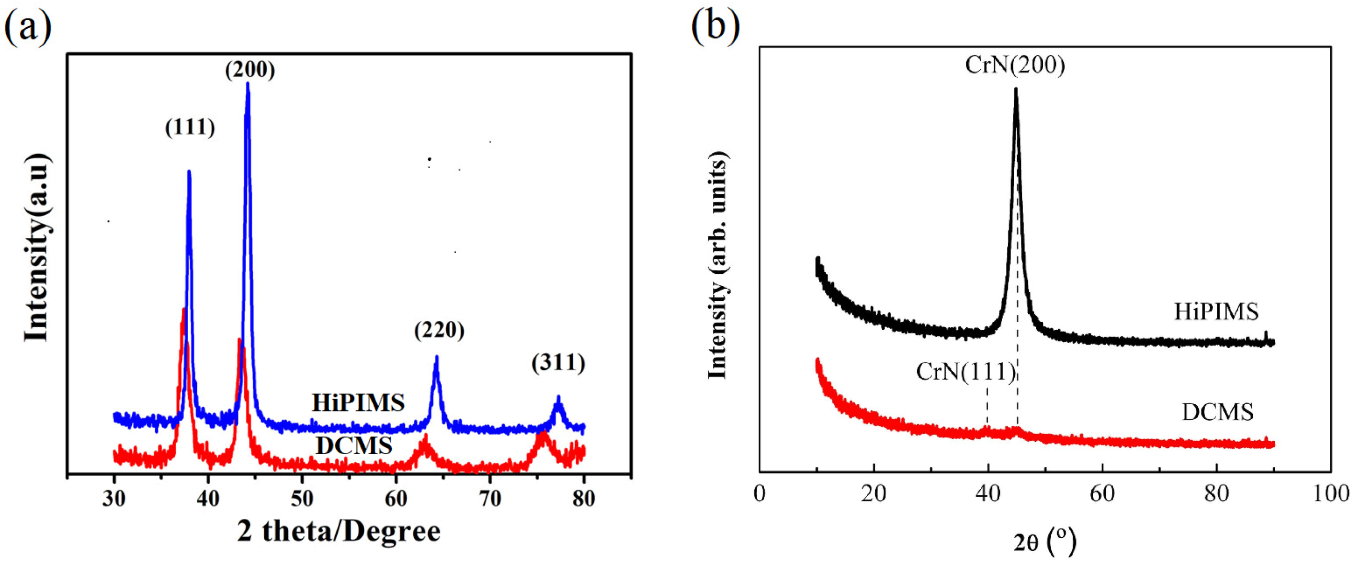
3.1. Texture
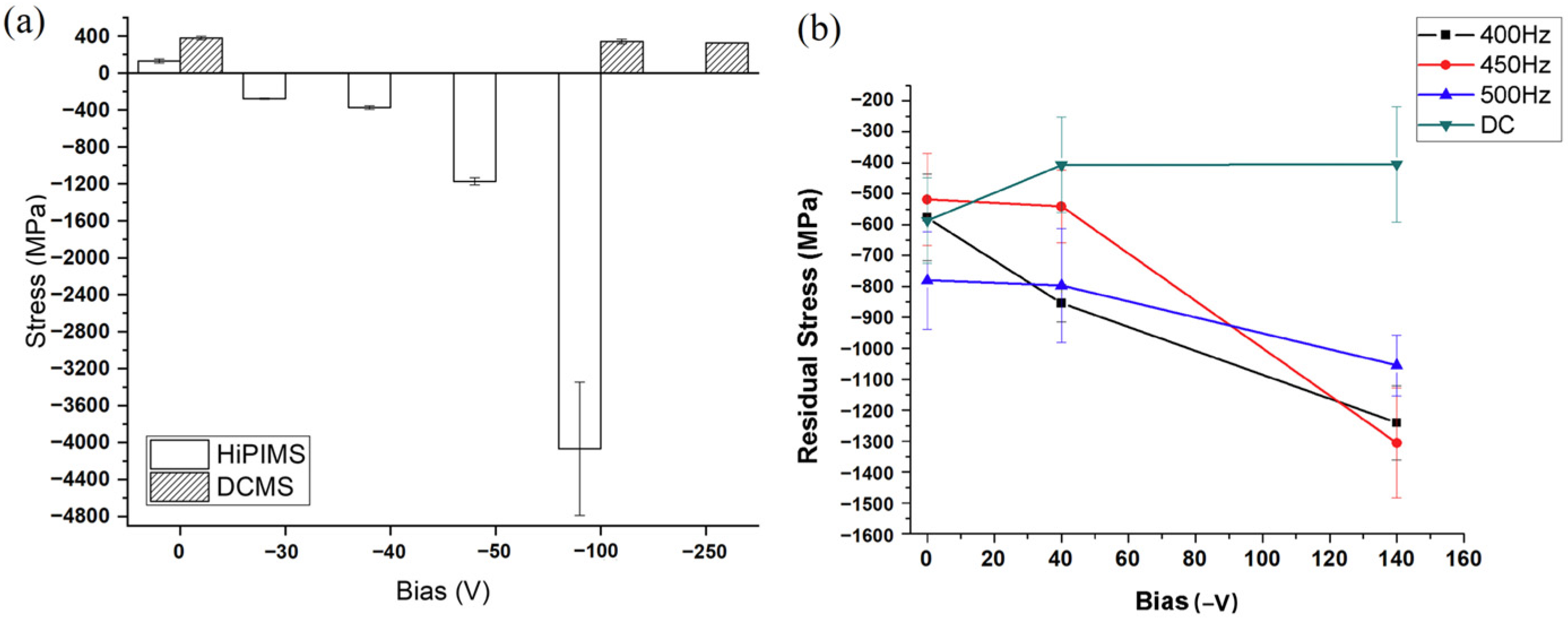
3.2. Residual Stress
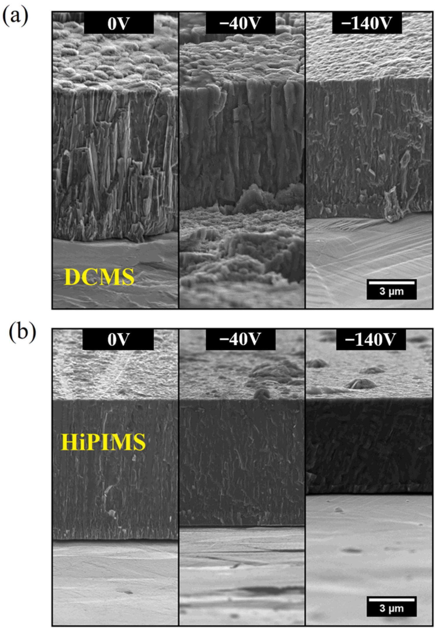
3.3. Micromorphology
4. The Influence of HiPIMS and DCMS Techniques on Mechanical and Corrosion Behaviors of CrN Coatings
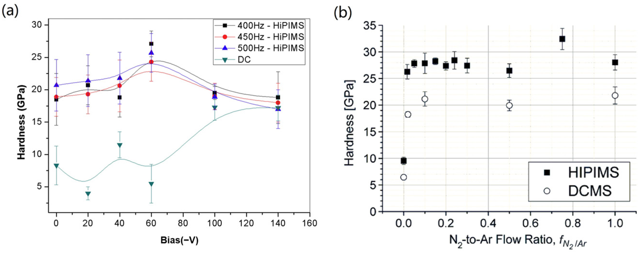
4.1. Hardness
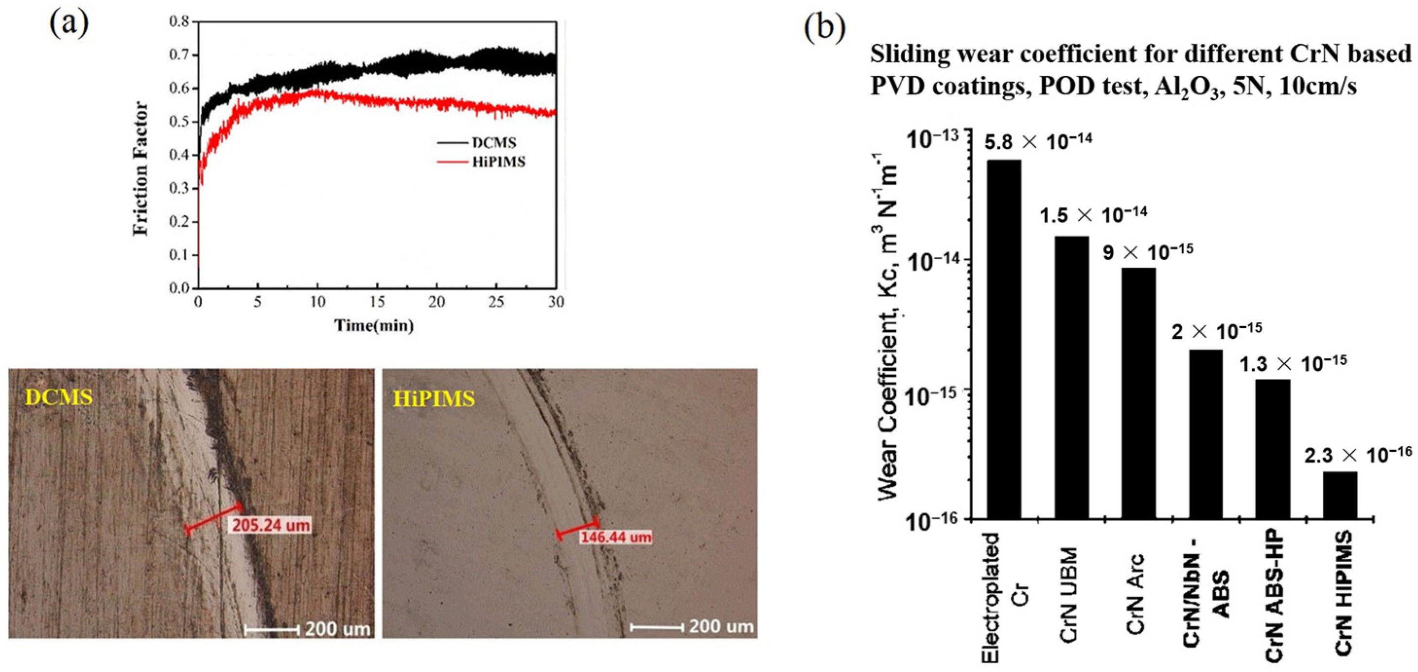
4.2. Tribological Properties
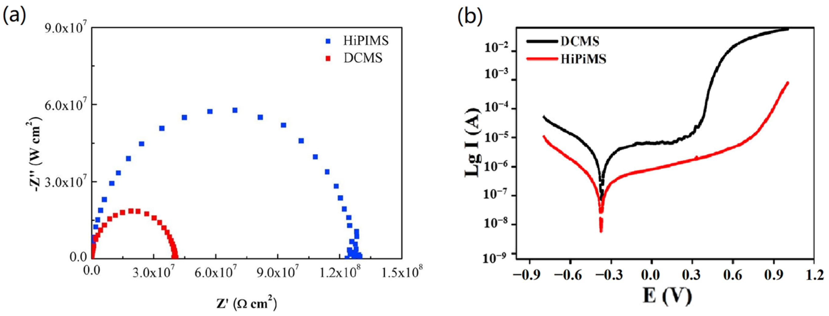
4.3. Electrochemical Behavior
5. Prospects
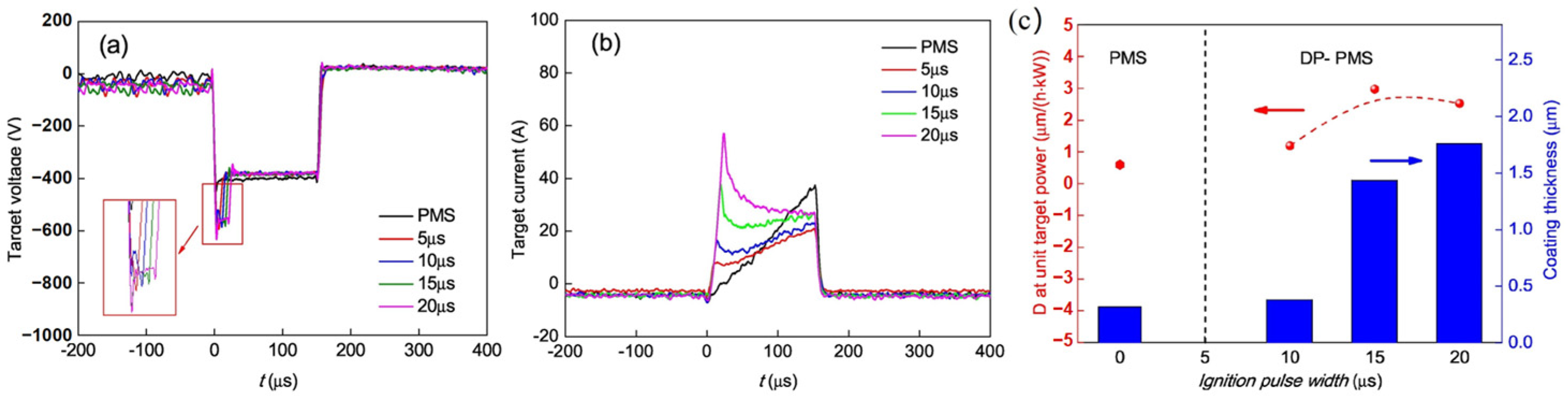
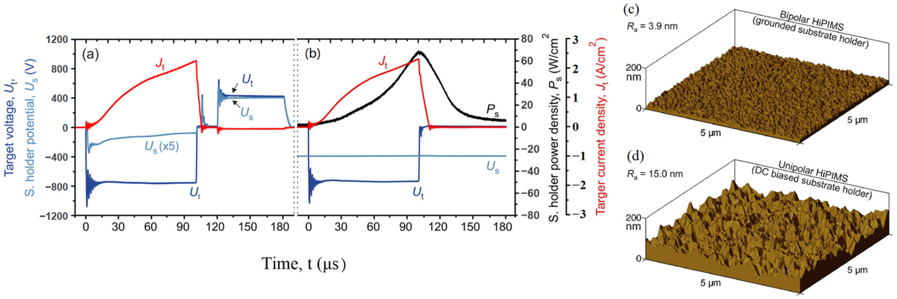
5.1. Innovative Use of HiPIMS Waveforms
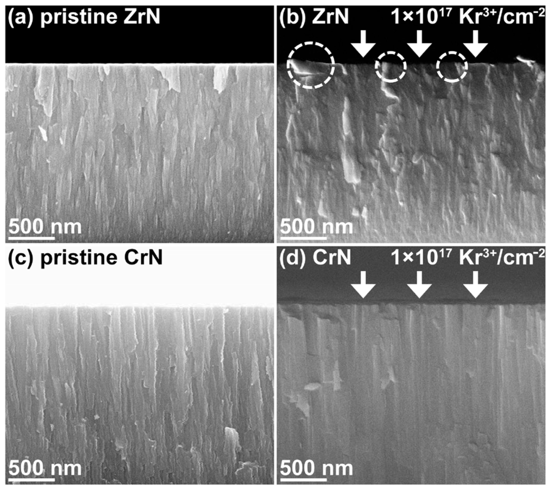
5.2. Irradiation Resistance and Corrosion Protection for Liquid Heavy Metals
6. Conclusions
Author Contributions
Funding
Institutional Review Board Statement
Informed Consent Statement
Data Availability Statement
Conflicts of Interest
References
- Kobayashi, K. First-Principles Study of the Electronic Properties of Transition Metal Nitride Surfaces. Surf. Sci. 2001, 493, 665–670. [Google Scholar] [CrossRef]
- Häglund, J.; Fernández Guillermet, A.; Grimvall, G.; Körling, M. Theory of Bonding in Transition-Metal Carbides and Nitrides. Phys. Rev. B 1993, 48, 11685–11691. [Google Scholar] [CrossRef] [PubMed]
- Goyenola, C.; Gueorguiev, G.K.; Stafström, S.; Hultman, L. Fullerene-like CSx: A First-Principles Study of Synthetic Growth. Chem. Phys. Lett. 2011, 506, 86–91. [Google Scholar] [CrossRef]
- Löfler, L.; Hahn, R.; Mayrhofer, P.H.; Bartosik, M.; Holec, D. Mechanical Properties of CrN-Based Superlattices: Impact of Magnetism. Acta Mater. 2021, 218, 117095. [Google Scholar] [CrossRef]
- Guo, S.; Sun, H. Superhardness Induced by Grain Boundary Vertical Sliding in (001)-Textured ZrB2 and TiB2 Nano Films. Acta Mater. 2021, 218, 117212. [Google Scholar] [CrossRef]
- Ma, F.; Li, J.; Zeng, Z.; Gao, Y. Structural, Mechanical and Tribocorrosion Behaviour in Artificial Seawater of CrN/AlN Nano-Multilayer Coatings on F690 Steel Substrates. Appl. Surf. Sci. 2018, 428, 404–414. [Google Scholar] [CrossRef]
- Ou, Y.X.; Lin, J.; Tong, S.; Che, H.L.; Sproul, W.D.; Lei, M.K. Wear and Corrosion Resistance of CrN/TiN Superlattice Coatings Deposited by a Combined Deep Oscillation Magnetron Sputtering and Pulsed Dc Magnetron Sputtering. Appl. Surf. Sci. 2015, 351, 332–343. [Google Scholar] [CrossRef]
- Zhou, F.; Ma, Q.; Zhang, M. Comparison of Tribological Properties of CrN, CrTiN and CrTiBN Coatings Sliding against SiC and SUS440C Balls in Water. Appl. Phys. A 2020, 126, 796. [Google Scholar] [CrossRef]
- Liu, L.; Ruan, Q.; Wu, Z.; Li, T.; Zuo, W.; Huang, C.; Wu, Y.; Wu, Z.; Fu, R.K.Y.; Chu, P.K. Hard and Tough CrN Coatings Strengthened by High-Density Distorted Coherent Grain Boundaries. J. Alloys Compd. 2022, 894, 162139. [Google Scholar] [CrossRef]
- Qi, Z.; Wei, B.; Wang, J.; Yang, Y.; Wang, Z. Nanostructured Porous CrN Thin Films by Oblique Angle Magnetron Sputtering for Symmetric Supercapacitors. J. Alloys Compd. 2019, 806, 953–959. [Google Scholar] [CrossRef]
- Arias, D.F.; Gómez, A.; Vélez, J.M.; Souza, R.M.; Olaya, J.J. A Mechanical and Tribological Study of Cr/CrN Multilayer Coatings. Mater. Chem. Phys. 2015, 160, 131–140. [Google Scholar] [CrossRef]
- Liu, H.; Wang, X.; Pei, C.; Sun, D. Tribological Properties and Corrosion Resistance of CrSiN Coatings Prepared via Hybrid HiPIMS and DCMS. Mater. Res. Express 2019, 6, 086432. [Google Scholar] [CrossRef]
- Shan, L.; Wang, Y.; Li, J.; Chen, J. Effect of N2 Flow Rate on Microstructure and Mechanical Properties of PVD CrNx Coatings for Tribological Application in Seawater. Surf. Coat. Technol. 2014, 242, 74–82. [Google Scholar] [CrossRef]
- Qiu, Y.; Zhang, S.; Li, B.; Wang, Y.; Lee, J.-W.; Li, F.; Zhao, D. Improvement of Tribological Performance of CrN Coating via Multilayering with VN. Surf. Coat. Technol. 2013, 231, 357–363. [Google Scholar] [CrossRef]
- Sánchez-López, J.C.; Caro, A.; Alcalá, G.; Rojas, T.C. Tailoring CrNx Stoichiometry and Functionality by Means of Reactive HiPIMS. Surf. Coat. Technol. 2020, 401, 126235. [Google Scholar] [CrossRef]
- Biswas, B.; Purandare, Y.; Sugumaran, A.; Khan, I.; Hovsepian, P.E. Effect of Chamber Pressure on Defect Generation and Their Influence on Corrosion and Tribological Properties of HIPIMS Deposited CrN/NbN Coatings. Surf. Coat. Technol. 2018, 336, 84–91. [Google Scholar] [CrossRef]
- Ehiasarian, A.P. High Power Pulsed Magnetron Sputtered CrNx Films. Surf. Coat. Technol. 2003, 163, 267–272. [Google Scholar] [CrossRef]
- Hurkmans, T. Influence of Ion Bombardment on Structure and Properties of Unbalanced Magnetron Grown CrNx Coatings k. Surf. Coat. Technol. 1999, 114, 52–59. [Google Scholar] [CrossRef]
- Ruden, A.; Restrepo-Parra, E.; Paladines, A.U.; Sequeda, F. Corrosion Resistance of CrN Thin Films Produced by Dc Magnetron Sputtering. Appl. Surf. Sci. 2013, 270, 150–156. [Google Scholar] [CrossRef]
- Tranca, D.E.; Sobetkii, A.; Hristu, R.; Anton, S.R.; Vasile, E.; Stanciu, S.G.; Banica, C.K.; Fiorentis, E.; Constantinescu, D.; Stanciu, G.A. Structural and Mechanical Properties of CrN Thin Films Deposited on Si Substrate by Using Magnetron Techniques. Coatings 2023, 13, 219. [Google Scholar] [CrossRef]
- Liu, W.; Jiao, D.; Ding, H.; Qiu, W.; Zhong, X.; Liu, Z. Corrosion Resistance of CrN Film Deposited by High-Power Impulse Magnetron Sputtering on SS304 in a Simulated Environment for Proton Exchange Membrane Fuel Cells. Int. J. Hydrogen Energy 2023, 48, 25901–25917. [Google Scholar] [CrossRef]
- Aouadi, K.; Tlili, B.; Nouveau, C.; Besnard, A.; Chafra, M.; Souli, R. Influence of Substrate Bias Voltage on Corrosion and Wear Behavior of Physical Vapor Deposition CrN Coatings. J. Mater. Eng. Perform. 2019, 28, 2881–2891. [Google Scholar] [CrossRef]
- Abdallah, B.; Kakhia, M.; Alssadat, W.; Zetoun, W. Temperature Effect on Structural, Mechanical Properties and Corrosion Behaviour of CrN Thin Films Deposited by Magnetron Sputtering. Micro Nano Lett. 2020, 15, 678–683. [Google Scholar] [CrossRef]
- Polcar, T.; Martinez, R.; Vítů, T.; Kopecký, L.; Rodriguez, R.; Cavaleiro, A. High Temperature Tribology of CrN and Multilayered Cr/CrN Coatings. Surf. Coat. Technol. 2009, 203, 3254–3259. [Google Scholar] [CrossRef]
- Qi, Z.B.; Liu, B.; Wu, Z.T.; Zhu, F.P.; Wang, Z.C.; Wu, C.H. A Comparative Study of the Oxidation Behavior of Cr2N and CrN Coatings. Thin Solid Films 2013, 544, 515–520. [Google Scholar] [CrossRef]
- Zhang, Z.G.; Rapaud, O.; Bonasso, N.; Mercs, D.; Dong, C.; Coddet, C. Influence of RF Bias on the Deposition of CrN Studied by OES. Adv. Eng. Mater. 2008, 10, 628–633. [Google Scholar] [CrossRef]
- Kong, Q.; Ji, L.; Li, H.; Liu, X.; Wang, Y.; Chen, J.; Zhou, H. Composition, Microstructure, and Properties of CrNx Films Deposited Using Medium Frequency Magnetron Sputtering. Appl. Surf. Sci. 2011, 257, 2269–2274. [Google Scholar] [CrossRef]
- Elangovan, T.; Kuppusami, P.; Thirumurugesan, R.; Ganesan, V.; Mohandas, E.; Mangalaraj, D. Nanostructured CrN Thin Films Prepared by Reactive Pulsed DC Magnetron Sputtering. Mater. Sci. Eng. B 2010, 167, 17–25. [Google Scholar] [CrossRef]
- Ferreira, F.; Oliveira, J.C.; Cavaleiro, A. CrN Thin Films Deposited by HiPIMS in DOMS Mode. Surf. Coat. Technol. 2016, 291, 365–375. [Google Scholar] [CrossRef]
- Anders, A.; Andersson, J.; Ehiasarian, A. High Power Impulse Magnetron Sputtering: Current-Voltage-Time Characteristics Indicate the Onset of Sustained Self-Sputtering. J. Appl. Phys. 2007, 102, 113303. [Google Scholar] [CrossRef]
- Anders, A.; Yang, Y. Plasma Studies of a Linear Magnetron Operating in the Range from DC to HiPIMS. J. Appl. Phys. 2018, 123, 043302. [Google Scholar] [CrossRef]
- Hnilica, J.; Klein, P.; Vašina, P.; Snyders, R.; Britun, N. Revisiting Particle Dynamics in HiPIMS Discharges. II. Plasma Pulse Effects. J. Appl. Phys. 2020, 128, 043304. [Google Scholar] [CrossRef]
- Jablonka, L.; Moskovkin, P.; Zhang, Z.; Zhang, S.-L.; Lucas, S.; Kubart, T. Metal Filling by High Power Impulse Magnetron Sputtering. J. Phys. Appl. Phys. 2019, 52, 365202. [Google Scholar] [CrossRef]
- Gudmundsson, J.T.; Brenning, N.; Lundin, D.; Helmersson, U. High Power Impulse Magnetron Sputtering Discharge. J. Vac. Sci. Technol. Vac. Surf. Films 2012, 30, 030801. [Google Scholar] [CrossRef]
- Ferrec, A.; Keraudy, J.; Jacq, S.; Schuster, F.; Jouan, P.-Y.; Djouadi, M.A. Correlation between Mass-Spectrometer Measurements and Thin Film Characteristics Using DcMS and HiPIMS Discharges. Surf. Coat. Technol. 2014, 250, 52–56. [Google Scholar] [CrossRef]
- Deng, Y.; Chen, W.; Li, B.; Wang, C.; Kuang, T.; Li, Y. Physical Vapor Deposition Technology for Coated Cutting Tools: A Review. Ceram. Int. 2020, 46, 18373–18390. [Google Scholar] [CrossRef]
- Bandorf, R.; Sittinger, V.; Bräuer, G. High Power Impulse Magnetron Sputtering—HIPIMS. In Comprehensive Materials Processing; Elsevier: Amsterdam, The Netherlands, 2014; pp. 75–99. ISBN 978-0-08-096533-8. [Google Scholar]
- Alami, J.; Bolz, S.; Sarakinos, K. High Power Pulsed Magnetron Sputtering: Fundamentals and Applications. J. Alloys Compd. 2009, 483, 530–534. [Google Scholar] [CrossRef]
- Anders, A. A Review Comparing Cathodic Arcs and High Power Impulse Magnetron Sputtering (HiPIMS). Surf. Coat. Technol. 2014, 257, 308–325. [Google Scholar] [CrossRef]
- Helmersson, U.; Lattemann, M.; Bohlmark, J.; Ehiasarian, A.P.; Gudmundsson, J.T. Ionized Physical Vapor Deposition (IPVD): A Review of Technology and Applications. Thin Solid Films 2006, 513, 1–24. [Google Scholar] [CrossRef]
- Alami, J.; Maric, Z.; Busch, H.; Klein, F.; Grabowy, U.; Kopnarski, M. Enhanced Ionization Sputtering: A Concept for Superior Industrial Coatings. Surf. Coat. Technol. 2014, 255, 43–51. [Google Scholar] [CrossRef]
- Baptista, A.; Silva, F.J.G.; Porteiro, J.; Míguez, J.L.; Pinto, G.; Fernandes, L. On the Physical Vapour Deposition (PVD): Evolution of Magnetron Sputtering Processes for Industrial Applications. Procedia Manuf. 2018, 17, 746–757. [Google Scholar] [CrossRef]
- Sun, L.G.; Wu, G.; Wang, Q.; Lu, J. Nanostructural Metallic Materials: Structures and Mechanical Properties. Mater. Today 2020, 38, 114–135. [Google Scholar] [CrossRef]
- Neuville, S. Quantum Electronic Mechanisms of Atomic Rearrangements during Growth of Hard Carbon Films. Surf. Coat. Technol. 2011, 206, 703–726. [Google Scholar] [CrossRef]
- Sarakinos, K.; Alami, J.; Konstantinidis, S. High Power Pulsed Magnetron Sputtering: A Review on Scientific and Engineering State of the Art. Surf. Coat. Technol. 2010, 204, 1661–1684. [Google Scholar] [CrossRef]
- Ghailane, A.; Makha, M.; Larhlimi, H.; Alami, J. Design of Hard Coatings Deposited by HiPIMS and DcMS. Mater. Lett. 2020, 280, 128540. [Google Scholar] [CrossRef]
- Liew, W.Y.H.; Lim, H.P.; Melvin, G.J.H.; Dayou, J.; Jiang, Z.-T. Thermal Stability, Mechanical Properties, and Tribological Performance of TiAlXN Coatings: Understanding the Effects of Alloying Additions. J. Mater. Res. Technol. 2022, 17, 961–1012. [Google Scholar] [CrossRef]
- Li, Q.; Yang, L.; Wang, Z.; Zhang, H.; Liu, Z.; Chen, Q. The Superior Properties of CrN Coatings Prepared by High Power Pulsed Reactive Magnetron Sputtering. AIP Adv. 2020, 10, 015125. [Google Scholar] [CrossRef]
- Greczynski, G.; Jensen, J.; Hultman, L. CrNx Films Prepared by DC Magnetron Sputtering and High-Power Pulsed Magnetron Sputtering: A Comparative Study. IEEE Trans. Plasma Sci. 2010, 38, 3046–3056. [Google Scholar] [CrossRef]
- Anders, A.; Ni, P.; Rauch, A. Drifting Localization of Ionization Runaway: Unraveling the Nature of Anomalous Transport in High Power Impulse Magnetron Sputtering. J. Appl. Phys. 2012, 111, 053304. [Google Scholar] [CrossRef]
- Rossnagel, S.M. Deposition and Redeposition in Magnetrons. J. Vac. Sci. Technol. Vac. Surf. Films 1988, 6, 3049–3054. [Google Scholar] [CrossRef]
- Seo, S.-H.; In, J.-H.; Chang, H.-Y. Experimental Investigation of Plasma Dynamics in Dc and Short-Pulse Magnetron Discharges. Plasma Sources Sci. Technol. 2006, 15, 256–265. [Google Scholar] [CrossRef]
- Shimizu, T.; Zanáška, M.; Villoan, R.P.; Brenning, N.; Helmersson, U.; Lundin, D. Experimental Verification of Deposition Rate Increase, with Maintained High Ionized Flux Fraction, by Shortening the HiPIMS Pulse. Plasma Sources Sci. Technol. 2021, 30, 045006. [Google Scholar] [CrossRef]
- Anders, A. Fundamentals of Pulsed Plasmas for Materials Processing. Surf. Coat. Technol. 2004, 183, 301–311. [Google Scholar] [CrossRef]
- Anders, A. Deposition Rates of High Power Impulse Magnetron Sputtering: Physics and Economics. J. Vac. Sci. Technol. Vac. Surf. Films 2010, 28, 783–790. [Google Scholar] [CrossRef]
- Sproul, W.D.; Christie, D.J.; Carter, D.C. Control of Reactive Sputtering Processes. Thin Solid Films 2005, 491, 1–17. [Google Scholar] [CrossRef]
- Ellmer, K.; Welzel, T. Reactive Magnetron Sputtering of Transparent Conductive Oxide Thin Films: Role of Energetic Particle (Ion) Bombardment. J. Mater. Res. 2012, 27, 765–779. [Google Scholar] [CrossRef]
- Anders, A. Tutorial: Reactive High Power Impulse Magnetron Sputtering (R-HiPIMS). J. Appl. Phys. 2017, 121, 171101. [Google Scholar] [CrossRef]
- Čapek, J.; Kadlec, S. Return of Target Material Ions Leads to a Reduced Hysteresis in Reactive High Power Impulse Magnetron Sputtering: Experiment. J. Appl. Phys. 2017, 121, 171911. [Google Scholar] [CrossRef]
- Ferrec, A.; Kéraudy, J.; Jouan, P.-Y. Mass Spectrometry Analyzes to Highlight Differences between Short and Long HiPIMS Discharges. Appl. Surf. Sci. 2016, 390, 497–505. [Google Scholar] [CrossRef]
- Konstantinidis, S.; Dauchot, J.P.; Ganciu, M.; Ricard, A.; Hecq, M. Influence of Pulse Duration on the Plasma Characteristics in High-Power Pulsed Magnetron Discharges. J. Appl. Phys. 2006, 99, 013307. [Google Scholar] [CrossRef]
- Greczynski, G.; Jensen, J.; Böhlmark, J.; Hultman, L. Microstructure Control of CrNx Films during High Power Impulse Magnetron Sputtering. Surf. Coat. Technol. 2010, 205, 118–130. [Google Scholar] [CrossRef]
- Christie, D.J. Target Material Pathways Model for High Power Pulsed Magnetron Sputtering. J. Vac. Sci. Technol. Vac. Surf. Films 2005, 23, 330–335. [Google Scholar] [CrossRef]
- Ehiasarian, A.P.; Hovsepian, P.E.; Hultman, L.; Helmersson, U. Comparison of Microstructure and Mechanical Properties of Chromium Nitride-Based Coatings Deposited by High Power Impulse Magnetron Sputtering and by the Combined Steered Cathodic Arc/Unbalanced Magnetron Technique. Thin Solid Films 2004, 457, 270–277. [Google Scholar] [CrossRef]
- Buranawong, A.; Witit-Anun, N. Nanostructure and Microstructure Evolution of D.C. Reactive Magnetron Sputtered CrN Thin Films. Key Eng. Mater. 2016, 718, 57–61. [Google Scholar] [CrossRef]
- Zhao, Z.B.; Rek, Z.U.; Yalisove, S.M.; Bilello, J.C. Phase Formation and Structure of Magnetron Sputtered Chromium Nitride Films: In-Situ and Ex-Situ Studies. Surf. Coat. Technol. 2004, 185, 329–339. [Google Scholar] [CrossRef]
- Siriprom, W.; Chananonnawathorn, C.; Kongsriprapan, S.; Teanchai, K.; Herman; Horprathum, M. Preparation and Characterization of CrN Thin Film by DC Reactive Magnetron Sputtering. Mater. Today Proc. 2018, 5, 15224–15227. [Google Scholar] [CrossRef]
- Habibi, M.; Mirzaei, S.; Arman, A.; Jurečka, S.; Sadeghi, M.; Zelati, A.; Shakoury, R.; Tanhaee, E.; Ghobadi, N.; Ehteram, H.; et al. Microstructure, Fractal Geometry and Corrosion Properties of CrN Thin Films: The Effect of Shot Number and Angular Position. Mater. Today Commun. 2022, 32, 104072. [Google Scholar] [CrossRef]
- Cunha, L.; Andritschky, M.; Pischow, K.; Wang, Z. Microstructure of CrN Coatings Produced by PVD Techniques. Thin Solid Films 1999, 355–356, 465–471. [Google Scholar] [CrossRef]
- Bienk, E.J.; Reitz, H.; Mikkelsen, N.J. Wear and Friction Properties of Hard PVD Coatings. Surf. Coat. Technol. 1995, 76–77, 475–480. [Google Scholar] [CrossRef]
- Meunier, C.; Vives, S.; Bertrand, G. X-Ray Diffractometry Analysis of r.f.-Magnetron-Sputtered Chromium/Chromium Nitride Coatings. Surf. Coat. Technol. 1998, 107, 149–158. [Google Scholar] [CrossRef]
- Zhang, D.; Zuo, X.; Wang, Z.; Li, H.; Chen, R.; Wang, A.; Ke, P. Comparative Study on Protective Properties of CrN Coatings on the ABS Substrate by DCMS and HiPIMS Techniques. Surf. Coat. Technol. 2020, 394, 125890. [Google Scholar] [CrossRef]
- Bilek, M.M.M.; McKenzie, D.R. A Comprehensive Model of Stress Generation and Relief Processes in Thin Films Deposited with Energetic Ions. Surf. Coat. Technol. 2006, 200, 4345–4354. [Google Scholar] [CrossRef]
- Cemin, F.; Abadias, G.; Minea, T.; Furgeaud, C.; Brisset, F.; Solas, D.; Lundin, D. Benefits of Energetic Ion Bombardment for Tailoring Stress and Microstructural Evolution during Growth of Cu Thin Films. Acta Mater. 2017, 141, 120–130. [Google Scholar] [CrossRef]
- Renzelli, M.; Mughal, M.Z.; Sebastiani, M.; Bemporad, E. Design, Fabrication and Characterization of Multilayer Cr-CrN Thin Coatings with Tailored Residual Stress Profiles. Mater. Des. 2016, 112, 162–171. [Google Scholar] [CrossRef]
- Meindlhumer, M.; Brandt, L.R.; Zalesak, J.; Rosenthal, M.; Hruby, H.; Kopecek, J.; Salvati, E.; Mitterer, C.; Daniel, R.; Todt, J.; et al. Evolution of Stress Fields during Crack Growth and Arrest in a Brittle-Ductile CrN-Cr Clamped-Cantilever Analysed by X-Ray Nanodiffraction and Modelling. Mater. Des. 2021, 198, 109365. [Google Scholar] [CrossRef]
- Yin, D.; Peng, X.; Qin, Y.; Wang, Z. Impact of Residual Stress on the Adhesion and Tensile Fracture of TiN/CrN Multi-Layered Coatings from First Principles. Phys. E Low-Dimens. Syst. Nanostruct. 2012, 44, 1838–1845. [Google Scholar] [CrossRef]
- Teixeira, V. Mechanical Integrity in PVD Coatings Due to the Presence of Residual Stresses. Thin Solid Films 2001, 392, 276–281. [Google Scholar] [CrossRef]
- Rebholz, C.; Ziegele, H.; Leyland, A.; Matthews, A. Structure, Mechanical and Tribological Properties of Nitrogen-Containing Chromium Coatings Prepared by Reactive Magnetron Sputtering. Surf. Coat. Technol. 1999, 115, 222–229. [Google Scholar] [CrossRef]
- Kirchlechner, C.; Martinschitz, K.J.; Daniel, R.; Mitterer, C.; Keckes, J. Residual Stresses in Thermally Cycled CrN Coatings on Steel. Thin Solid Films 2008, 517, 1167–1171. [Google Scholar] [CrossRef]
- Guo, C.-Q.; Li, H.-Q.; Peng, Y.-L.; Dai, M.-J.; Lin, S.-S.; Shi, Q.; Wei, C.-B. Residual Stress and Tribological Behavior of Hydrogen-Free Al-DLC Films Prepared by HiPIMS under Different Bias Voltages. Surf. Coat. Technol. 2022, 445, 128713. [Google Scholar] [CrossRef]
- Oettel, H.; Wiedemann, R.; Preißler, S. Residual Stresses in Nitride Hard Coatings Prepared by Magnetron Sputtering and Arc Evaporation. Surf. Coat. Technol. 1995, 74–75, 273–278. [Google Scholar] [CrossRef]
- Ecker, W.; Keckes, J.; Krobath, M.; Zalesak, J.; Daniel, R.; Rosenthal, M.; Todt, J. Nanoscale Evolution of Stress Concentrations and Crack Morphology in Multilayered CrN Coating during Indentation: Experiment and Simulation. Mater. Des. 2020, 188, 108478. [Google Scholar] [CrossRef]
- Meindlhumer, M.; Zalesak, J.; Ecker, W.; Rosenthal, M.; Niese, S.; Gawlitza, P.; Hruby, H.; Mitterer, C.; Daniel, R.; Keckes, J.; et al. Nanoscale Stress Distributions and Microstructural Changes at Scratch Track Cross-Sections of a Deformed Brittle-Ductile CrN-Cr Bilayer. Mater. Des. 2020, 195, 109023. [Google Scholar] [CrossRef]
- Teixeira, V. Residual Stress and Cracking in Thin PVD Coatings. Vacuum 2002, 64, 393–399. [Google Scholar] [CrossRef]
- Gelfi, M.; La Vecchia, G.M.; Lecis, N.; Troglio, S. Relationship between Through-Thickness Residual Stress of CrN-PVD Coatings and Fatigue Nucleation Sites. Surf. Coat. Technol. 2005, 192, 263–268. [Google Scholar] [CrossRef]
- Asgaribakhtiari, H.; Majzoobi, G.H.; Elmkhah, H. On the Effect of Cr/CrN Nanolayered Coating Deposited by Arc-PVD Method on Axial Fretting Fatigue Behavior of Al7075-T6 Alloy. Surf. Coat. Technol. 2023, 454, 129176. [Google Scholar] [CrossRef]
- Yi, P.; Zhang, D.; Peng, L.; Lai, X. Impact of Film Thickness on Defects and the Graphitization of Nanothin Carbon Coatings Used for Metallic Bipolar Plates in Proton Exchange Membrane Fuel Cells. ACS Appl. Mater. Interfaces 2018, 10, 34561–34572. [Google Scholar] [CrossRef]
- Daniel, R.; Meindlhumer, M.; Zalesak, J.; Sartory, B.; Zeilinger, A.; Mitterer, C.; Keckes, J. Fracture Toughness Enhancement of Brittle Nanostructured Materials by Spatial Heterogeneity: A Micromechanical Proof for CrN/Cr and TiN/SiOx Multilayers. Mater. Des. 2016, 104, 227–234. [Google Scholar] [CrossRef]
- Elo, R.; Jacobson, S.; Kubart, T. Tailoring Residual Stresses in CrNx Films on Alumina and Silicon Deposited by High-Power Impulse Magnetron Sputtering. Surf. Coat. Technol. 2020, 397, 125990. [Google Scholar] [CrossRef]
- Bemporad, E.; Brisotto, M.; Depero, L.E.; Gelfi, M.; Korsunsky, A.M.; Lunt, A.J.G.; Sebastiani, M. A Critical Comparison between XRD and FIB Residual Stress Measurement Techniques in Thin Films. Thin Solid Films 2014, 572, 224–231. [Google Scholar] [CrossRef]
- Shiri, S.; Ashtijoo, P.; Odeshi, A.; Yang, Q. Evaluation of Stoney Equation for Determining the Internal Stress of DLC Thin Films Using an Optical Profiler. Surf. Coat. Technol. 2016, 308, 98–100. [Google Scholar] [CrossRef]
- Guimaraes, M.C.R.; de Castilho, B.C.N.M.; Nossa, T.d.S.; Avila, P.R.T.; Cucatti, S.; Alvarez, F.; Garcia, J.L.; Pinto, H.C. On the Effect of Substrate Oscillation on CrN Coatings Deposited by HiPIMS and DcMS. Surf. Coat. Technol. 2018, 340, 112–120. [Google Scholar] [CrossRef]
- Kateb, M.; Hajihoseini, H.; Gudmundsson, J.T.; Ingvarsson, S. The Importance of HiPIMS Ionization FLux Fraction on the Film Microstructure and Surface Roughness: A Molecular Dynamic Simulation; Háskóli Íslands University of Iceland: Reykjavik, Iceland, 2020. [Google Scholar]
- Thulasi Raman, K.H.; Kiran, M.S.R.N.; Ramamurty, U.; Mohan Rao, G. Structural and Mechanical Properties of Room Temperature Sputter Deposited CrN Coatings. Mater. Res. Bull. 2012, 47, 4463–4466. [Google Scholar] [CrossRef]
- Kabir, M.S.; Munroe, P.; Zhou, Z.; Xie, Z. Structure and Mechanical Properties of Graded Cr/CrN/CrTiN Coatings Synthesized by Close Field Unbalanced Magnetron Sputtering. Surf. Coat. Technol. 2017, 309, 779–789. [Google Scholar] [CrossRef]
- Buranawong, A.; Witit-Anun, N. Structure and Oxidation Behavior CrN Thin Films Deposited Using DC Reactive Magnetron Sputtering. Key Eng. Mater. 2019, 798, 122–127. [Google Scholar] [CrossRef]
- Paulitsch, J.; Schenkel, M.; Zufraß, T.; Mayrhofer, P.H.; Münz, W.-D. Structure and Properties of High Power Impulse Magnetron Sputtering and DC Magnetron Sputtering CrN and TiN Films Deposited in an Industrial Scale Unit. Thin Solid Films 2010, 518, 5558–5564. [Google Scholar] [CrossRef]
- Li, J.; Cho, J.; Ding, J.; Charalambous, H.; Xue, S.; Wang, H.; Phuah, X.L.; Jian, J.; Wang, X.; Ophus, C.; et al. Nanoscale Stacking Fault–Assisted Room Temperature Plasticity in Flash-Sintered TiO2. Sci. Adv. 2019, 5, eaaw5519. [Google Scholar] [CrossRef]
- Audronis, M.; Bellido-Gonzalez, V.; Daniel, B. Control of Reactive High Power Impulse Magnetron Sputtering Processes. Surf. Coat. Technol. 2010, 204, 2159–2164. [Google Scholar] [CrossRef]
- Panjan, M.; Franz, R.; Anders, A. Asymmetric Particle Fluxes from Drifting Ionization Zones in Sputtering Magnetrons. Plasma Sources Sci. Technol. 2014, 23, 025007. [Google Scholar] [CrossRef]
- Bobzin, K.; Brögelmann, T.; Kruppe, N.C.; Arghavani, M.; Engels, M. Correlation of HPPMS Plasma and Coating Properties Using Artificial Neural Networks. Surf. Coat. Technol. 2018, 349, 1130–1136. [Google Scholar] [CrossRef]
- Ehiasarian, A.P.; Andersson, J.; Anders, A. Distance-Dependent Plasma Composition and Ion Energy in High Power Impulse Magnetron Sputtering. J. Phys. Appl. Phys. 2010, 43, 275204. [Google Scholar] [CrossRef]
- Aiempanakit, M.; Helmersson, U.; Aijaz, A.; Larsson, P.; Magnusson, R.; Jensen, J.; Kubart, T. Effect of Peak Power in Reactive High Power Impulse Magnetron Sputtering of Titanium Dioxide. Surf. Coat. Technol. 2011, 205, 4828–4831. [Google Scholar] [CrossRef]
- Thomann, A.-L.; Caillard, A.; Raza, M.; El Mokh, M.; Cormier, P.A.; Konstantinidis, S. Energy Flux Measurements during Magnetron Sputter Deposition Processes. Surf. Coat. Technol. 2019, 377, 124887. [Google Scholar] [CrossRef]
- Kumar, P.; Seema; Gupta, M.; Avasthi, S. Fully Dense, Highly Conductive Nanocrystalline TiN Diffusion Barrier on Steel via Reactive High Power Impulse Magnetron Sputtering. Thin Solid Films 2021, 722, 138578. [Google Scholar] [CrossRef]
- Zuo, X.; Chen, R.; Ke, P.; Wang, A. Gas Breakdown and Discharge Formation in High-Power Impulse Magnetron Sputtering. IEEE Trans. Plasma Sci. 2019, 47, 1215–1222. [Google Scholar] [CrossRef]
- Palmucci, M.; Britun, N.; Silva, T.; Snyders, R.; Konstantinidis, S. Mass Spectrometry Diagnostics of Short-Pulsed HiPIMS Discharges. J. Phys. Appl. Phys. 2013, 46, 215201. [Google Scholar] [CrossRef]
- Bohlmark, J.; Alami, J.; Christou, C.; Ehiasarian, A.P.; Helmersson, U. Ionization of Sputtered Metals in High Power Pulsed Magnetron Sputtering. J. Vac. Sci. Technol. A 2004, 23, 18–22. [Google Scholar] [CrossRef]
- Gudmundsson, J.T. Ionization Mechanism in the High Power Impulse Magnetron Sputtering (HiPIMS) Discharge. J. Phys. Conf. Ser. 2008, 100, 082013. [Google Scholar] [CrossRef]
- Lazar, J.; Vlček, J.; Rezek, J. Ion Flux Characteristics and Efficiency of the Deposition Processes in High Power Impulse Magnetron Sputtering of Zirconium. J. Appl. Phys. 2010, 108, 063307. [Google Scholar] [CrossRef]
- Lin, J.; Moore, J.J.; Sproul, W.D.; Mishra, B.; Rees, J.A.; Wu, Z.; Chistyakov, R.; Abraham, B. Ion Energy and Mass Distributions of the Plasma during Modulated Pulse Power Magnetron Sputtering. Surf. Coat. Technol. 2009, 203, 3676–3685. [Google Scholar] [CrossRef]
- Lundin, D.; Čada, M.; Hubička, Z. Ionization of Sputtered Ti, Al, and C Coupled with Plasma Characterization in HiPIMS. Plasma Sources Sci. Technol. 2015, 24, 035018. [Google Scholar] [CrossRef]
- Moskovkin, P.; Maszl, C.; Schierholz, R.; Breilmann, W.; Petersen, J.; Pflug, A.; Muller, J.; Raza, M.; Konstantinidis, S.; von Keudell, A.; et al. Link between Plasma Properties with Morphological, Structural and Mechanical Properties of Thin Ti Films Deposited by High Power Impulse Magnetron Sputtering. Surf. Coat. Technol. 2021, 418, 127235. [Google Scholar] [CrossRef]
- Bobzin, K.; Bagcivan, N.; Immich, P.; Bolz, S.; Cremer, R.; Leyendecker, T. Mechanical Properties and Oxidation Behaviour of (Al,Cr)N and (Al,Cr,Si)N Coatings for Cutting Tools Deposited by HPPMS. Thin Solid Films 2008, 517, 1251–1256. [Google Scholar] [CrossRef]
- Zhang, X.; Tian, X.; Gong, C.; Liu, X.; Li, J.; Zhu, J.; Lin, H. Effect of Plasma Nitriding Ion Current Density on Tribological Properties of Composite CrAlN Coatings. Ceram. Int. 2022, 48, 3954–3962. [Google Scholar] [CrossRef]
- Lv, Y.; Ji, L.; Liu, X.; Li, H.; Zhou, H.; Chen, J. Influence of Substrate Bias Voltage on Structure and Properties of the CrAlN Films Deposited by Unbalanced Magnetron Sputtering. Appl. Surf. Sci. 2012, 258, 3864–3870. [Google Scholar] [CrossRef]
- Kauffmann, F.; Ji, B.; Dehm, G.; Gao, H.; Arzt, E. A Quantitative Study of the Hardness of a Superhard Nanocrystalline Titanium Nitride/Silicon Nitride Coating. Scr. Mater. 2005, 52, 1269–1274. [Google Scholar] [CrossRef]
- Zauner, L.; Hahn, R.; Aschauer, E.; Wojcik, T.; Davydok, A.; Hunold, O.; Polcik, P.; Riedl, H. Assessing the Fracture and Fatigue Resistance of Nanostructured Thin Films. Acta Mater. 2022, 239, 118260. [Google Scholar] [CrossRef]
- Liu, L.; Ruan, Q.; Xiao, S.; Meng, X.; Huang, C.; Wu, Y.; Fu, R.K.Y.; Chu, P.K. Fabrication and Hydrogen Permeation Resistance of Dense CrN Coatings. Surf. Coat. Technol. 2022, 437, 128326. [Google Scholar] [CrossRef]
- Gigax, J.G.; El-Atwani, O.; McCulloch, Q.; Aytuna, B.; Efe, M.; Fensin, S.; Maloy, S.A.; Li, N. Micro- and Mesoscale Mechanical Properties of an Ultra-Fine Grained CrFeMnNi High Entropy Alloy Produced by Large Strain Machining. Scr. Mater. 2020, 178, 508–512. [Google Scholar] [CrossRef]
- Lu, K. Stabilizing Nanostructures in Metals Using Grain and Twin Boundary Architectures. Nat. Rev. Mater. 2016, 1, 16019. [Google Scholar] [CrossRef]
- Stranak, V.; Hubicka, Z.; Cada, M.; Drache, S.; Tichy, M.; Hippler, R. Investigation of Ionized Metal Flux in Enhanced High Power Impulse Magnetron Sputtering Discharges. J. Appl. Phys. 2014, 115, 153301. [Google Scholar] [CrossRef]
- Bohlmark, J.; Lattemann, M.; Gudmundsson, J.T.; Ehiasarian, A.P.; Aranda Gonzalvo, Y.; Brenning, N.; Helmersson, U. The Ion Energy Distributions and Ion Flux Composition from a High Power Impulse Magnetron Sputtering Discharge. Thin Solid Films 2006, 515, 1522–1526. [Google Scholar] [CrossRef]
- Li, Z.; Liu, C.; Chen, Q.; Yang, J.; Liu, J.; Yang, H.; Zhang, W.; Zhang, R.; He, L.; Long, J.; et al. Microstructure, High-Temperature Corrosion and Steam Oxidation Properties of Cr/CrN Multilayer Coatings Prepared by Magnetron Sputtering. Corros. Sci. 2021, 191, 109755. [Google Scholar] [CrossRef]
- Song, G.-H.; Yang, X.-P.; Xiong, G.-L.; Lou, Z.; Chen, L.-J. The Corrosive Behavior of Cr/CrN Multilayer Coatings with Different Modulation Periods. Vacuum 2013, 89, 136–141. [Google Scholar] [CrossRef]
- Petrogalli, C.; Montesano, L.; Gelfi, M.; La Vecchia, G.M.; Solazzi, L. Tribological and Corrosion Behavior of CrN Coatings: Roles of Substrate and Deposition Defects. Surf. Coat. Technol. 2014, 258, 878–885. [Google Scholar] [CrossRef]
- Khamseh, S.; Nose, M.; Kawabata, T.; Nagae, T.; Matsuda, K.; Ikeno, S. A Comparative Study of CrAlN Films Synthesized by Dc and Pulsed Dc Reactive Magnetron Facing Target Sputtering System with Different Pulse Frequencies. J. Alloys Compd. 2010, 508, 191–195. [Google Scholar] [CrossRef]
- Kharrat, M.; Baccar, M.; Dammak, F. (Eds.) Advances in Mechanical Engineering, Materials and Mechanics: Selected Contributions from the 7th International Conference on Advances in Mechanical Engineering and Mechanics, ICAMEM 2019, December 16–18, 2019, Hammamet, Tunisia; Lecture Notes in Mechanical Engineering; Springer International Publishing: Cham, Switzerland, 2021; ISBN 978-3-030-52070-0. [Google Scholar]
- Zhang, X.; Chang, W.; Zhang, H.; Zhou, Z.; Xie, S.; Duo, S. Al Content Effects on Mechanical and Tribological Properties of Cr/CrN/CrAlN Multilayer Nanocomposite Coatings. IOP Conf. Ser. Mater. Sci. Eng. 2019, 678, 012163. [Google Scholar] [CrossRef]
- Li, Z.; Munroe, P.; Jiang, Z.; Zhao, X.; Xu, J.; Zhou, Z.; Jiang, J.; Fang, F.; Xie, Z. Designing Superhard, Self-Toughening CrAlN Coatings through Grain Boundary Engineering. Acta Mater. 2012, 60, 5735–5744. [Google Scholar] [CrossRef]
- Wang, D.; Lin, S.; Yang, Z.; Yin, Z.; Ye, F.; Gao, X.; Qiao, Y.; Xue, Y.; Yang, H.; Zhou, K. Failure Mechanisms of CrN and CrAlN Coatings for Solid Particle Erosion Resistance. Vacuum 2022, 204, 111313. [Google Scholar] [CrossRef]
- Li, J.; Chen, Y.; Xue, S.; Wang, H.; Zhang, X. Comparison of Size Dependent Strengthening Mechanisms in Ag/Fe and Ag/Ni Multilayers. Acta Mater. 2016, 114, 154–163. [Google Scholar] [CrossRef]
- Tillmann, W.; Stangier, D.; Roese, P.; Shamout, K.; Berges, U.; Westphal, C.; Debus, J. Structural and Mechanical Properties of Carbon Incorporation in DC/HiPIMS CrAlN Coatings. Surf. Coat. Technol. 2019, 374, 774–783. [Google Scholar] [CrossRef]
- Kabir, M.S.; Munroe, P.; Zhou, Z.; Xie, Z. Study of the Structure, Properties, Scratch Resistance and Deformation Behaviour of Graded Cr-CrN-Cr(1-x)AlxN Coatings. Ceram. Int. 2018, 44, 11364–11373. [Google Scholar] [CrossRef]
- Wang, D.; Tian, T.; Lin, S.; Zhao, N.; Liu, H.; Liu, J.; Wang, Y.; Li, L.; Li, H.; Shi, Q.; et al. Tensile Mechanism of Wear-Resistant Cr/CrN/Cr/CrAlN Multilayer Film. Vacuum 2023, 207, 111405. [Google Scholar] [CrossRef]
- Chen, X.; Gao, H.; Bai, Y.; Yang, H. Thermal Failure Mechanism of Multilayer Brittle TiN/CrAlN Films. Ceram. Int. 2018, 44, 8138–8144. [Google Scholar] [CrossRef]
- Kabir, M.S.; Munroe, P.; Zhou, Z.; Xie, Z. Wear Behavior of Graded Cr-CrN-Cr(1−x)Al(x)N Coatings Synthesized by Closed-Field Unbalanced Magnetron Sputtering for Advanced Machining Operations. Ceram. Int. 2018, 44, 7723–7733. [Google Scholar] [CrossRef]
- Cai, Q.; Li, S.; Pu, J.; Bai, X.; Wang, H.; Cai, Z.; Wang, X. Corrosion Resistance and Antifouling Activities of Silver-Doped CrN Coatings Deposited by Magnetron Sputtering. Surf. Coat. Technol. 2018, 354, 194–202. [Google Scholar] [CrossRef]
- Oje, A.M.; Ogwu, A.A.; Oje, A.I.; Tsendzughul, N.; Ur Rahman, S. A Comparative Study of the Corrosion and Ion Release Behaviour of Chromium Oxide Coatings Exposed to Saline, Ringer’s and Hank’s Physiological Solutions. Corros. Sci. 2020, 167, 108533. [Google Scholar] [CrossRef]
- Wang, Q.; Zhang, B.; Ren, Y.; Yang, K. A Self-Healing Stainless Steel: Role of Nitrogen in Eliminating Detrimental Effect of Cold Working on Pitting Corrosion Resistance. Corros. Sci. 2018, 145, 55–66. [Google Scholar] [CrossRef]
- Tang, P.; He, D.; Li, W.; Shang, L.; Zhai, H.; Wang, L.; Zhang, G. Achieving Superior Hot Corrosion Resistance by PVD/HVOF Duplex Design. Corros. Sci. 2020, 175, 108845. [Google Scholar] [CrossRef]
- Han, X.; Xue, J.; Peng, S.; Zhang, H. An Interesting Oxidation Phenomenon of Cr Coatings on Zry-4 Substrates in High Temperature Steam Environment. Corros. Sci. 2019, 156, 117–124. [Google Scholar] [CrossRef]
- Pan, T.J.; Dai, Y.J.; Jiang, J.; Xiang, J.H.; Yang, Q.Q.; Li, Y.S. Anti-Corrosion Performance of the Conductive Bilayer CrC/CrN Coated 304SS Bipolar Plate in Acidic Environment. Corros. Sci. 2022, 206, 110495. [Google Scholar] [CrossRef]
- Wu, H.; Tian, Q.; Tian, X.; Gong, C.; Zhang, X.; Wu, Z. Enhancement of Discharge and Deposition Rate in Dual-Pulse Pulsed Magnetron Sputtering: Effect of Ignition Pulse Width. Surf. Coat. Technol. 2019, 374, 383–392. [Google Scholar] [CrossRef]
- Batková, Š.; Čapek, J.; Rezek, J.; Čerstvý, R.; Zeman, P. Effect of Positive Pulse Voltage in Bipolar Reactive HiPIMS on Crystal Structure, Microstructure and Mechanical Properties of CrN Films. Surf. Coat. Technol. 2020, 393, 125773. [Google Scholar] [CrossRef]
- Van Nieuwenhove, R.; Andersson, V.; Balak, J.; Oberländer, B. In-Pile Testing of CrN, TiAlN, and AlCrN Coatings on Zircaloy Cladding in the Halden Reactor Citation; ASTM International: West Conshohocken, PA, USA, 2018. [Google Scholar] [CrossRef]
- Glasbrenner, H.; Gröschel, F. Exposure of Pre-Stressed T91 Coated with TiN, CrN and DLC to Pb–55.5Bi. J. Nucl. Mater. 2006, 356, 213–221. [Google Scholar] [CrossRef]
- Kurata, Y.; Futakawa, M. Corrosion of CrN-Coated Steels in Liquid Pb-Bi. Mater. Trans. 2007, 48, 519–525. [Google Scholar] [CrossRef]
- Serag, E.; Caers, B.; Schuurmans, P.; Lucas, S.; Haye, E. Challenges and Coating Solutions for Wear and Corrosion inside Lead Bismuth Eutectic: A Review. Surf. Coat. Technol. 2022, 441, 128542. [Google Scholar] [CrossRef]
- Zhang, X.; Hattar, K.; Chen, Y.; Shao, L.; Li, J.; Sun, C.; Yu, K.; Li, N.; Taheri, M.L.; Wang, H.; et al. Radiation Damage in Nanostructured Materials. Prog. Mater. Sci. 2018, 96, 217–321. [Google Scholar] [CrossRef]
- Li, J.; Fan, C.; Ding, J.; Xue, S.; Chen, Y.; Li, Q.; Wang, H.; Zhang, X. In Situ Heavy Ion Irradiation Studies of Nanopore Shrinkage and Enhanced Radiation Tolerance of Nanoporous Au. Sci. Rep. 2017, 7, 39484. [Google Scholar] [CrossRef]
- Li, J.; Yu, K.Y.; Chen, Y.; Song, M.; Wang, H.; Kirk, M.A.; Li, M.; Zhang, X. In Situ Study of Defect Migration Kinetics and Self-Healing of Twin Boundaries in Heavy Ion Irradiated Nanotwinned Metals. Nano Lett. 2015, 15, 2922–2927. [Google Scholar] [CrossRef]
- Uglov, V.V.; Abadias, G.; Zlotski, S.V.; Saladukhin, I.A.; Malashevich, A.A.; Kozlovskiy, A.L.; Zdorovets, M.V. Blistering in Helium-Ion-Irradiated Zirconium, Aluminum, and Chromium Nitride Films. J. Surf. Investig. X-ray Synchrotron Neutron Tech. 2020, 14, 359–365. [Google Scholar] [CrossRef]
- Shang, Z.; Ding, J.; Fan, C.; Chen, D.; Li, J.; Zhang, Y.; Wang, Y.; Wang, H.; Zhang, X. He Ion Irradiation Response of a Gradient T91 Steel. Acta Mater. 2020, 196, 175–190. [Google Scholar] [CrossRef]
- Shang, Z.; Fan, C.; Ding, J.; Xue, S.; Gabriel, A.; Shao, L.; Voisin, T.; Wang, Y.M.; Niu, T.; Li, J.; et al. Heavy Ion Irradiation Response of an Additively Manufactured 316LN Stainless Steel. J. Nucl. Mater. 2021, 546, 152745. [Google Scholar] [CrossRef]
- Wu, Z.; Wu, Y.; Wang, Q. A Comparative Investigation on Structure Evolution of ZrN and CrN Coatings against Ion Irradiation. Heliyon 2019, 5, e01370. [Google Scholar] [CrossRef]
- Li, J.; Wang, H.; Zhang, X. A Review on the Radiation Response of Nanoporous Metallic Materials. JOM 2018, 70, 2753–2764. [Google Scholar] [CrossRef]
- Li, J.; Fan, C.; Li, Q.; Wang, H.; Zhang, X. In Situ Studies on Irradiation Resistance of Nanoporous Au through Temperature-Jump Tests. Acta Mater. 2018, 143, 30–42. [Google Scholar] [CrossRef]
- Li, J.; Chen, Y.; Wang, H.; Zhang, X. In Situ Study on Enhanced Heavy Ion Irradiation Tolerance of Porous Mg. Scr. Mater. 2018, 144, 13–17. [Google Scholar] [CrossRef]
- Song, L.; Huang, B.; Li, J.; Ma, X.; Liu, M.; Jiang, J.; Hu, Y. Effects of Ion Irradiation on Cr, CrN, and TiAlCrN Coated Zircaloy-4 for Accident Tolerant Fuel Claddings. Ann. Nucl. Energy 2021, 156, 108206. [Google Scholar] [CrossRef]
- Xiang, Y.; Liu, C.; Li, Z.; Liu, H.; Yang, J.; Yang, H.; Zhang, R.; He, L.; Liu, J.; Long, J.; et al. Interface Stability and Microstructural Evolution of the (Cr/CrN)24-Coated Zirconium Alloy under Different Thermal Shock Temperatures. Surf. Coat. Technol. 2022, 429, 127947. [Google Scholar] [CrossRef]
- Wan, Q.; Yang, B.; Liu, H.D.; Mei, Q.S.; Chen, Y.M. Ion Irradiation Tolerance of Ti Si N Nanocomposite Coating. Surf. Coat. Technol. 2016, 305, 165–169. [Google Scholar] [CrossRef]
- Novaković, M.; Popović, M.; Bibić, N. Ion-Beam Irradiation Effects on Reactively Sputtered CrN Thin Films. Nucl. Instrum. Methods Phys. Res. Sect. B Beam Interact. Mater. At. 2010, 268, 2883–2887. [Google Scholar] [CrossRef]

| Samples | Ecorr (V) | Icorr (A/cm2) | |
|---|---|---|---|
| The results of polarization curve fitting by Li et al. [48] | CrN (DCMS) | −0.37 | 2.8 × 10⁻⁷ |
| CrN (HiPIMS) | −0.34 | 2.75 × 10⁻⁸ |
| DCMS | HiPIMS | ||
|---|---|---|---|
| Deposition parameters [15,48,49,72,90,93] | Voltage (V) | 200–500 | 600–1200 |
| Peak current (A) | 0.5–10 | 80–600 | |
| Peak power (kW) | 0.5–4 | 8–400 | |
| Microstructure and morphology | Texture (substrates: Si (100)) [72] | Predominately (111) | Predominately (200) |
| Crystal size (nm) [15] | 28 | 8 | |
| Residual stresses (MPa) [93] | −400 | −1200 | |
| Microstructure [72] | The nanocrystalline and amorphous composite structure | The compact nanocrystalline structure | |
| Morphology [48] | 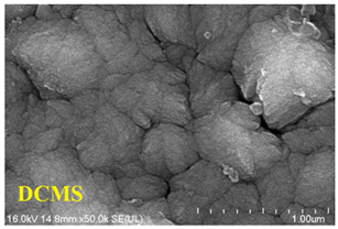 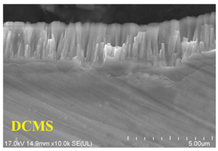 | 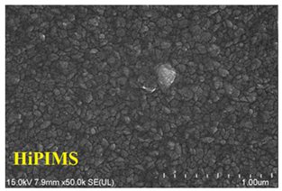  | |
| Mechanical property | Hardness (GPa) [72] | 15 | 22 |
| Elastic modulus (GPa) [72] | 240 | 270 | |
| Friction coefficient [48] | 0.64 | 0.545 |
Disclaimer/Publisher’s Note: The statements, opinions and data contained in all publications are solely those of the individual author(s) and contributor(s) and not of MDPI and/or the editor(s). MDPI and/or the editor(s) disclaim responsibility for any injury to people or property resulting from any ideas, methods, instructions or products referred to in the content. |
© 2023 by the authors. Licensee MDPI, Basel, Switzerland. This article is an open access article distributed under the terms and conditions of the Creative Commons Attribution (CC BY) license (https://creativecommons.org/licenses/by/4.0/).
Share and Cite
Bai, H.; Li, J.; Gao, J.; Ni, J.; Bai, Y.; Jian, J.; Zhao, L.; Bai, B.; Cai, Z.; He, J.; et al. Comparison of CrN Coatings Prepared Using High-Power Impulse Magnetron Sputtering and Direct Current Magnetron Sputtering. Materials 2023, 16, 6303. https://doi.org/10.3390/ma16186303
Bai H, Li J, Gao J, Ni J, Bai Y, Jian J, Zhao L, Bai B, Cai Z, He J, et al. Comparison of CrN Coatings Prepared Using High-Power Impulse Magnetron Sputtering and Direct Current Magnetron Sputtering. Materials. 2023; 16(18):6303. https://doi.org/10.3390/ma16186303
Chicago/Turabian StyleBai, Heda, Jin Li, Jialai Gao, Jinyang Ni, Yaxiong Bai, Jie Jian, Lin Zhao, Bowen Bai, Zeyun Cai, Jianchao He, and et al. 2023. "Comparison of CrN Coatings Prepared Using High-Power Impulse Magnetron Sputtering and Direct Current Magnetron Sputtering" Materials 16, no. 18: 6303. https://doi.org/10.3390/ma16186303
APA StyleBai, H., Li, J., Gao, J., Ni, J., Bai, Y., Jian, J., Zhao, L., Bai, B., Cai, Z., He, J., Chen, H., Leng, X., & Liu, X. (2023). Comparison of CrN Coatings Prepared Using High-Power Impulse Magnetron Sputtering and Direct Current Magnetron Sputtering. Materials, 16(18), 6303. https://doi.org/10.3390/ma16186303