
Investigation on the Coaxial-Annulus-Argon-Assisted Water-Jet-Guided Laser Machining of Hard-to-Process Materials


Abstract
:1. Introduction
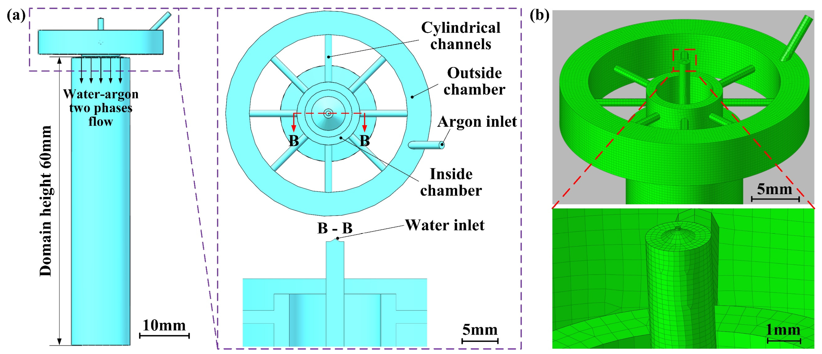
2. Numerical Setup
- (1)
- The dynamic viscosities and densities of water and argon phases are considered to be constants.
- (2)
- The absorption of laser energy during its transmission in the water jet is disregarded, and the internal temperature of the calculation domain is held constant at 300 K.
- (3)
- The non-slip boundary is applied between the fluids and the wall. Additionally, the velocity gradient of fluids is assumed to be perpendicular to the wall.
- (4)
- In the initial stage, the calculation domain is filled with ambient air, meaning that the initial volume fractions of water and argon are both zero.
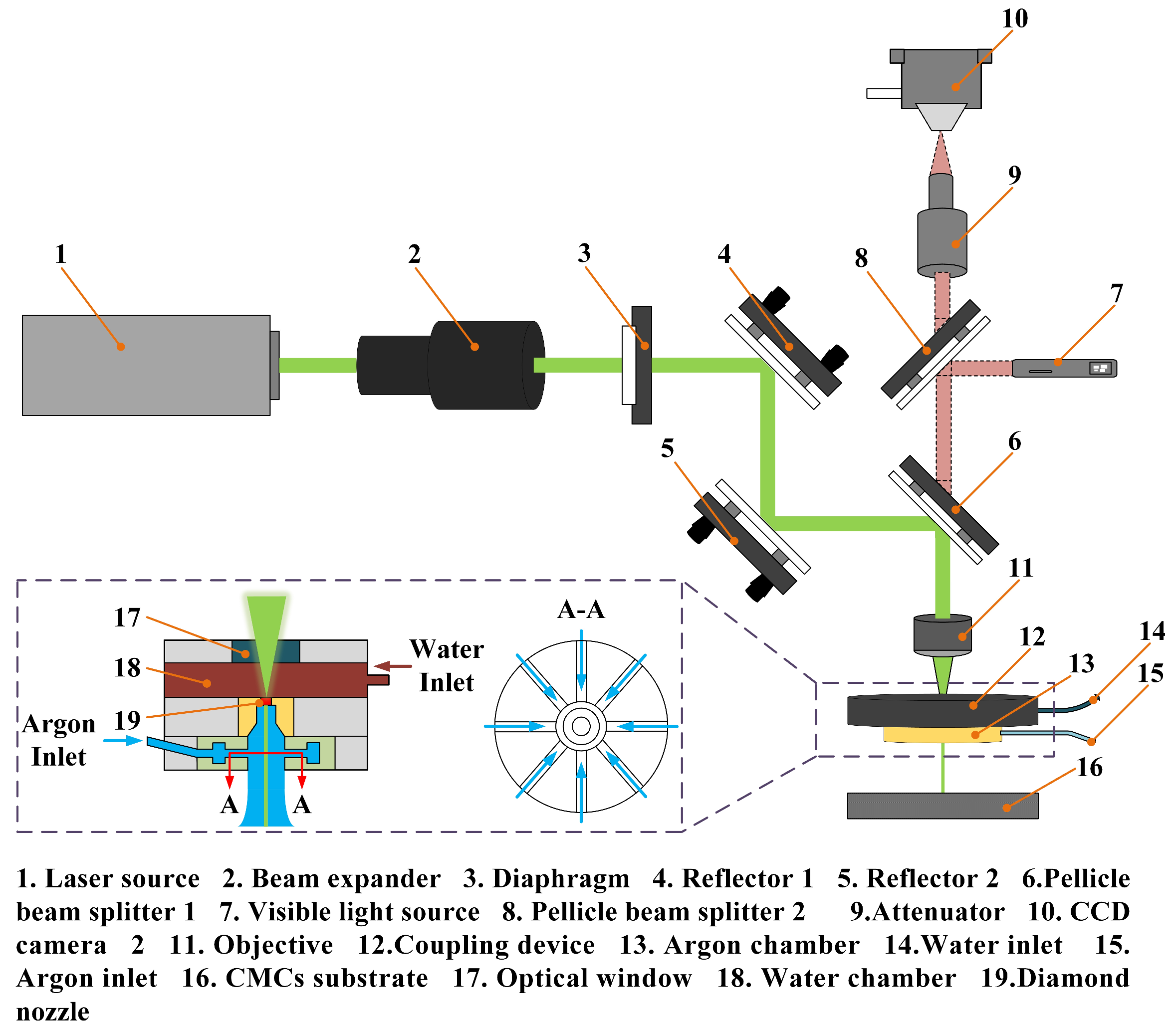
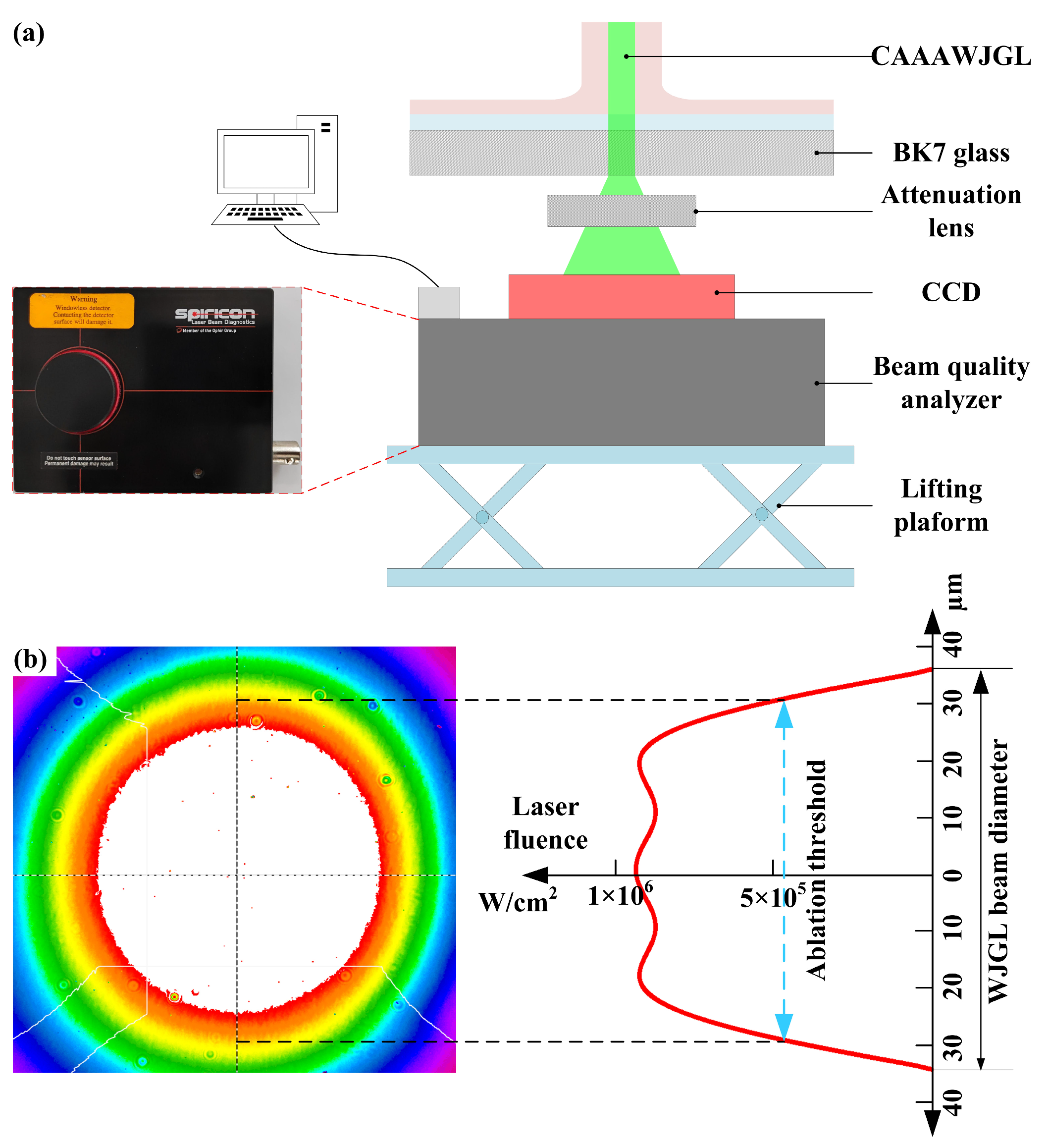
3. Experimental Setup
4. Results and Discussions
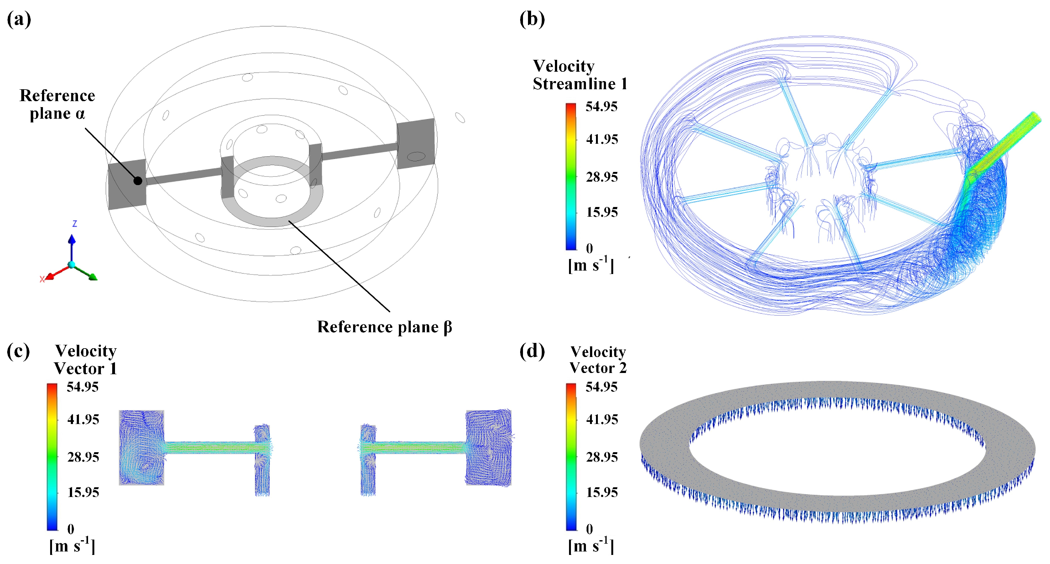
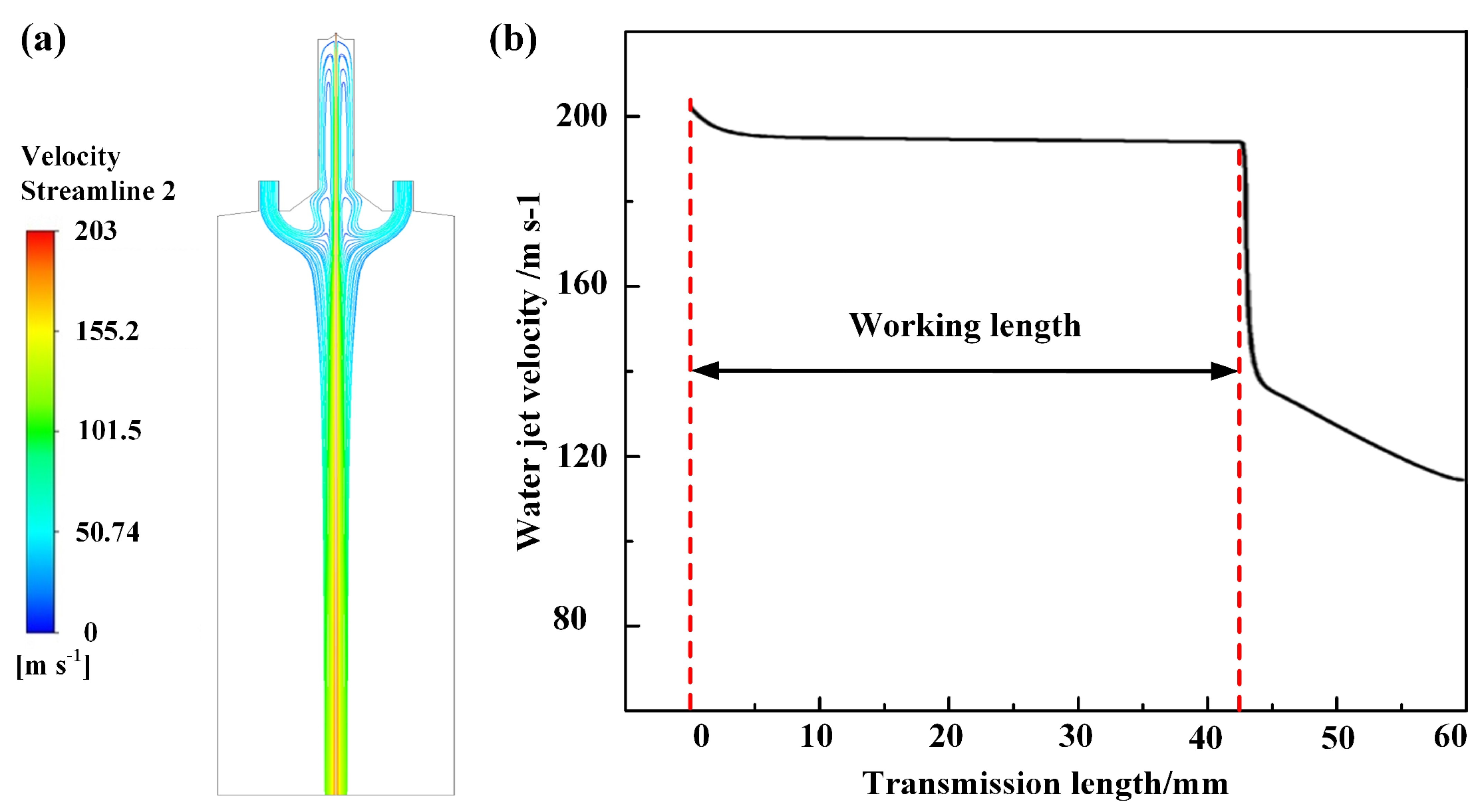
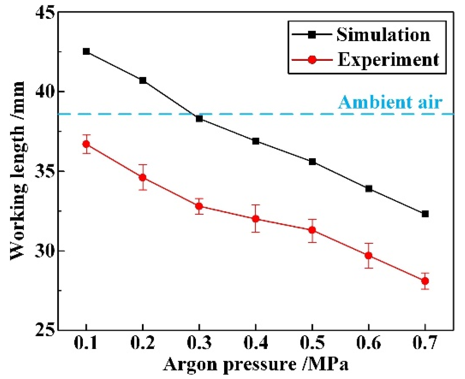
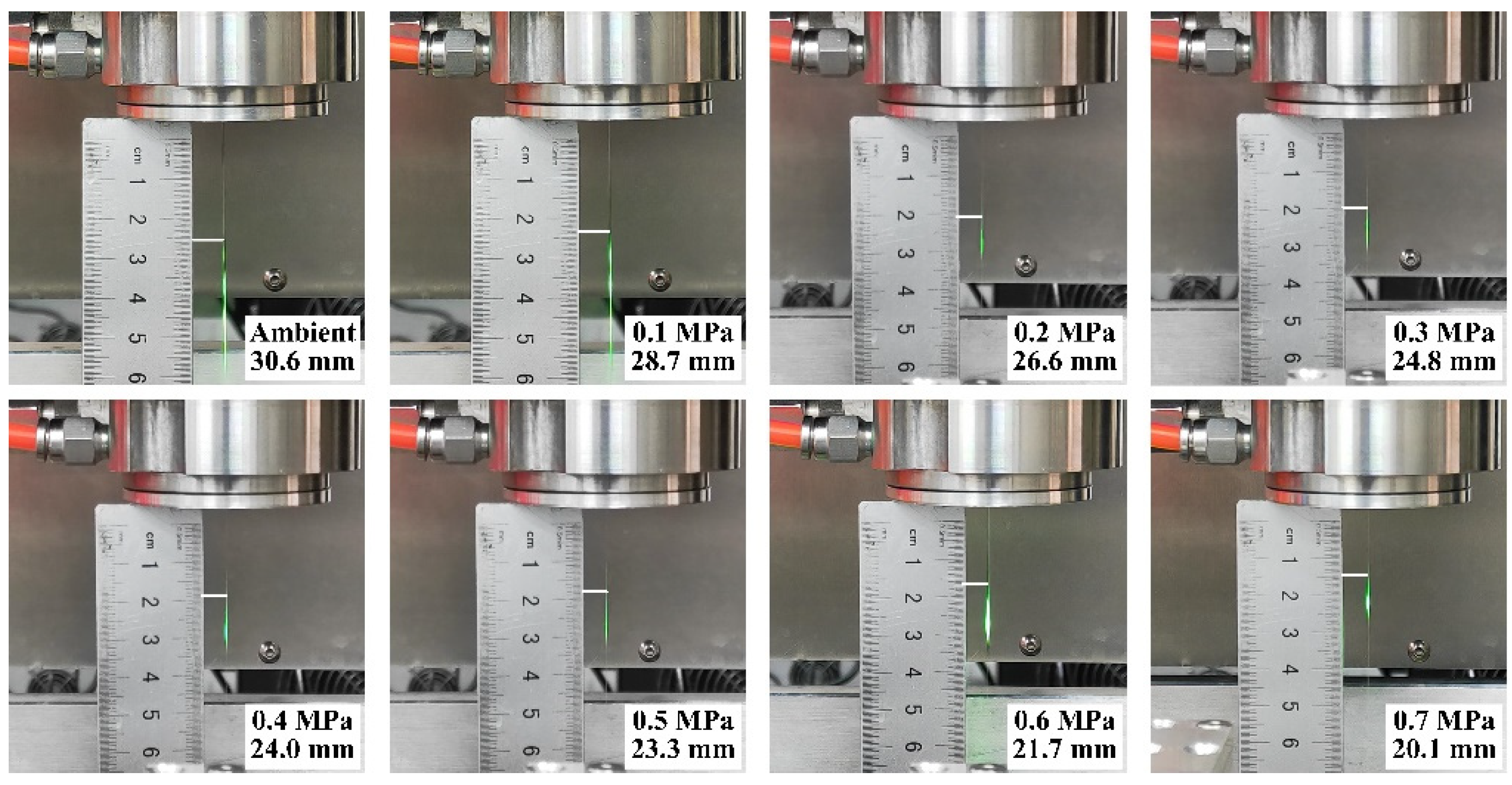
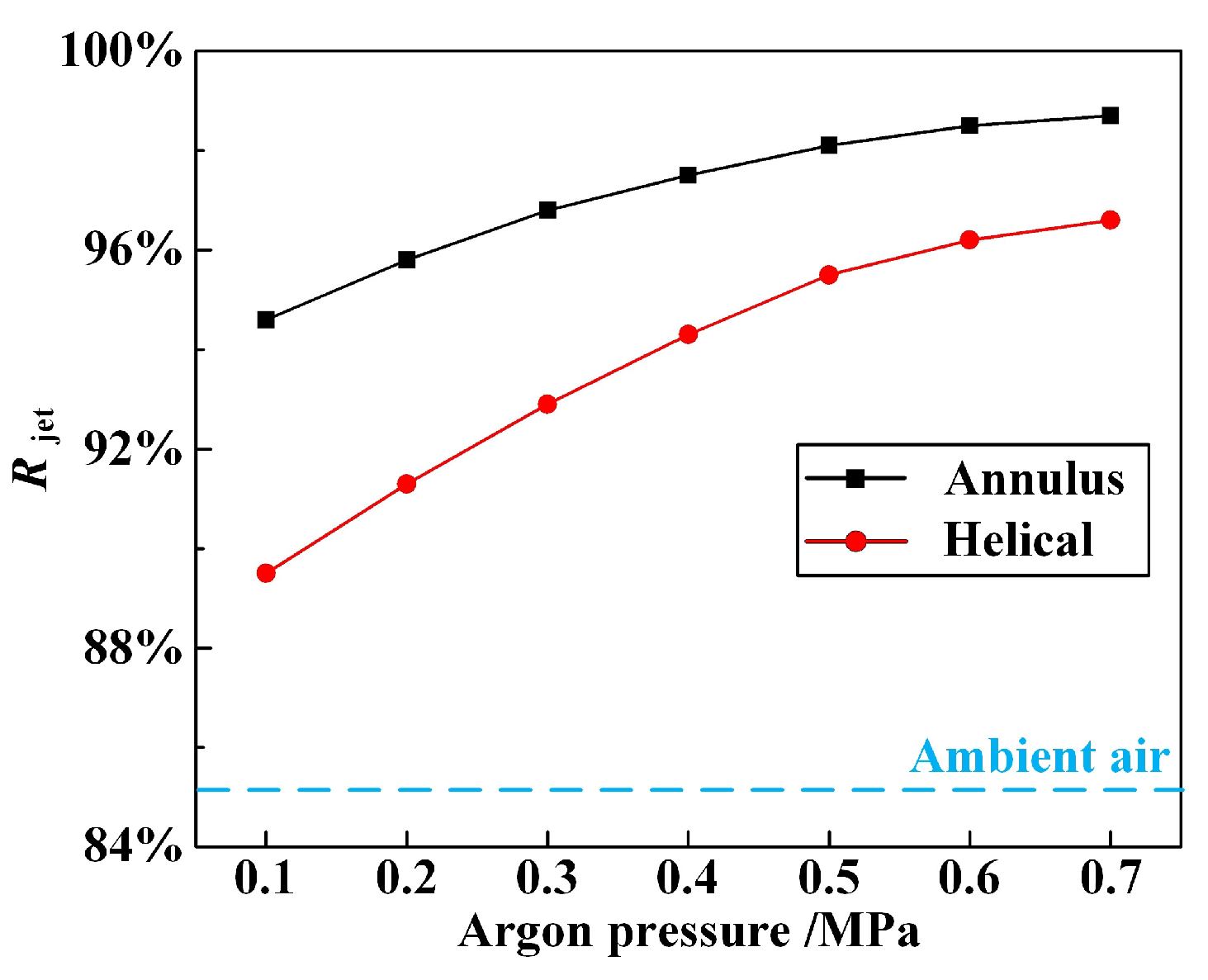
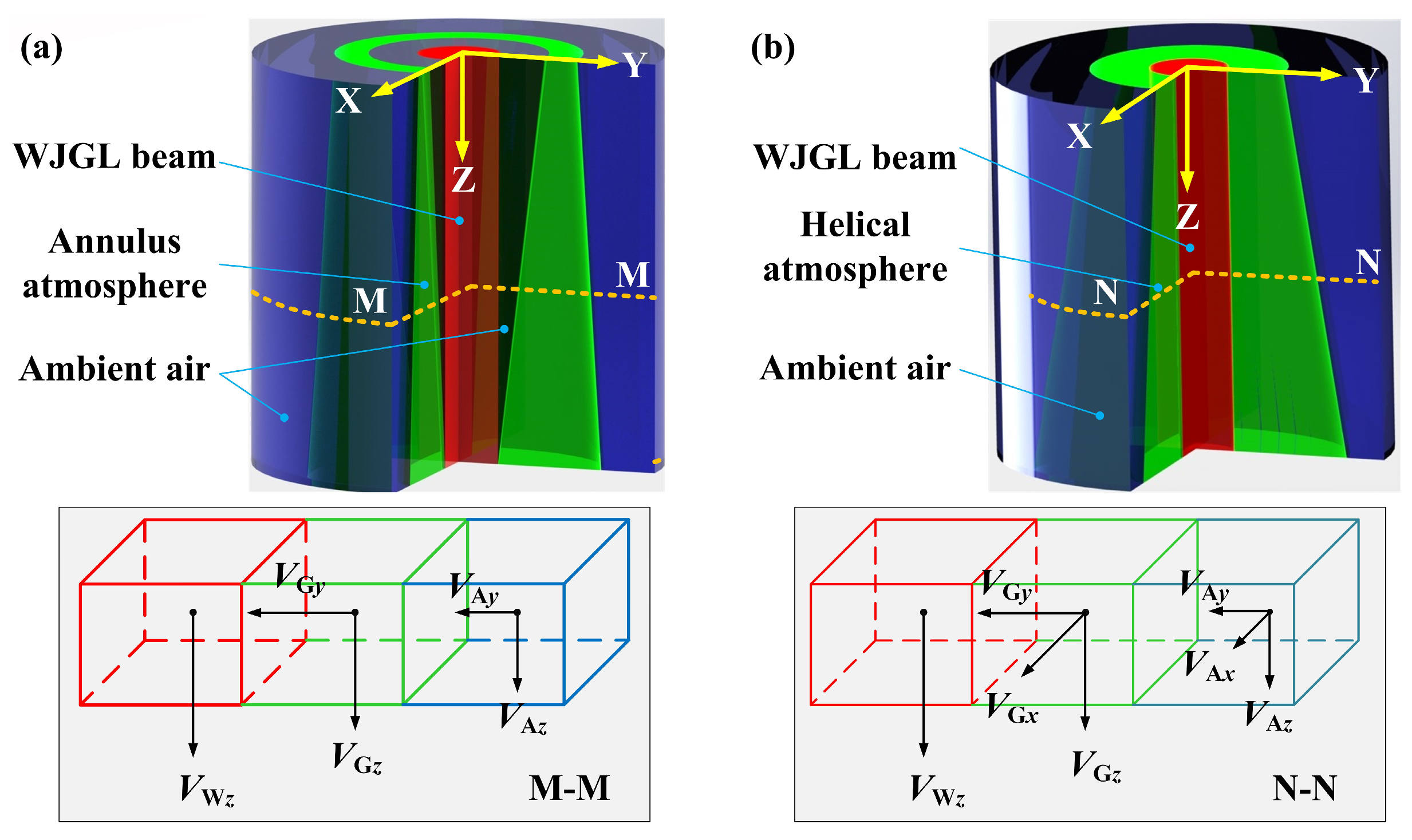
4.1. The Influence of Coaxial Annulus Argon Atmosphere on WJGL Beam
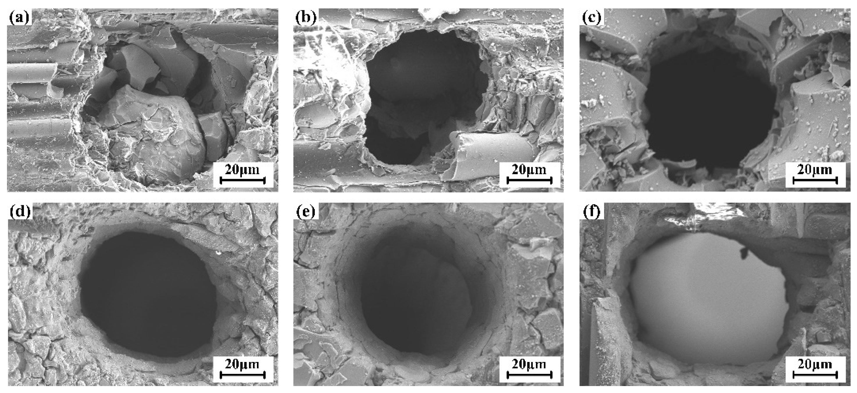
4.2. Single-Point CAAAWJGL Percussion Drilling Experiments
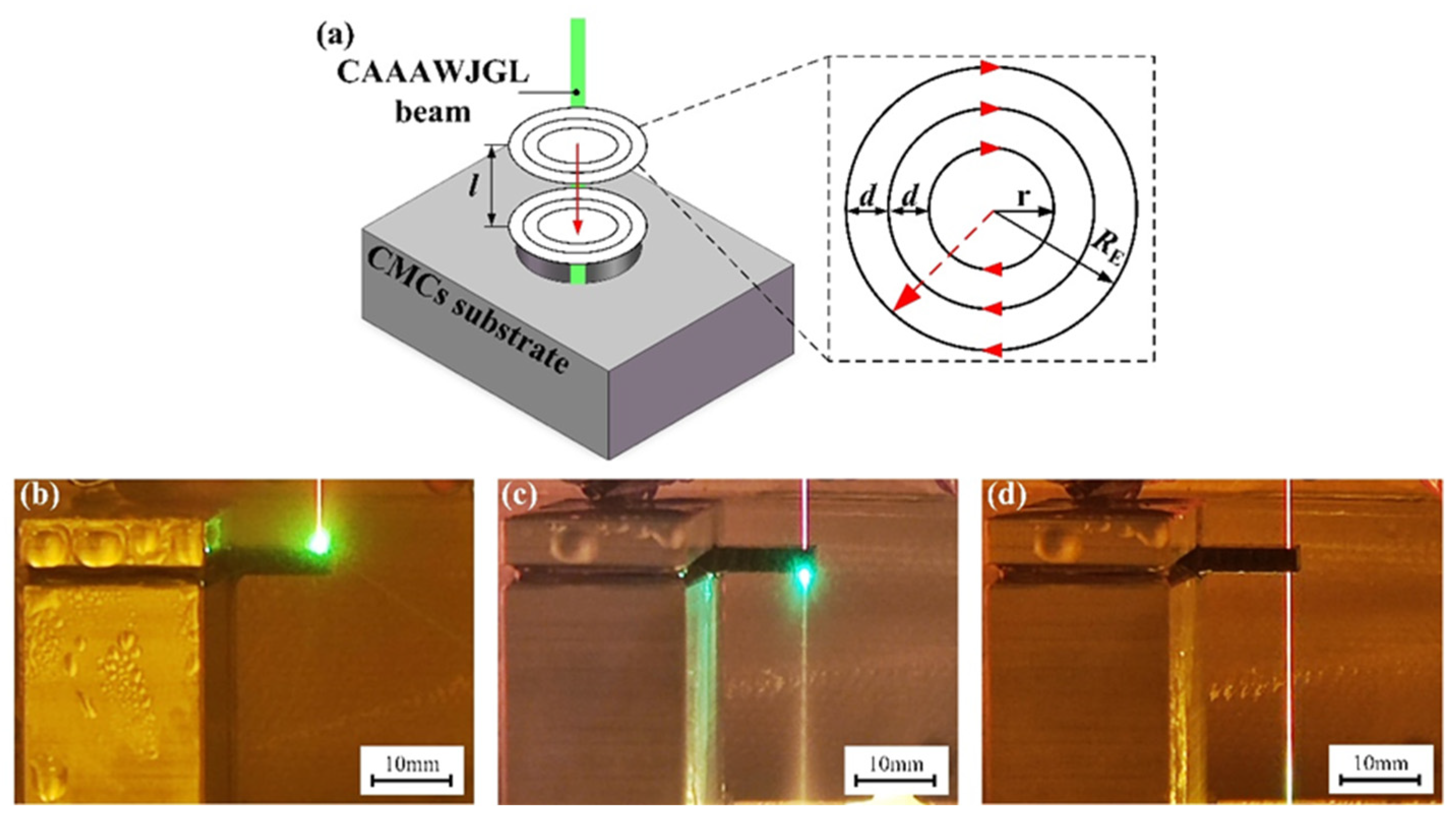
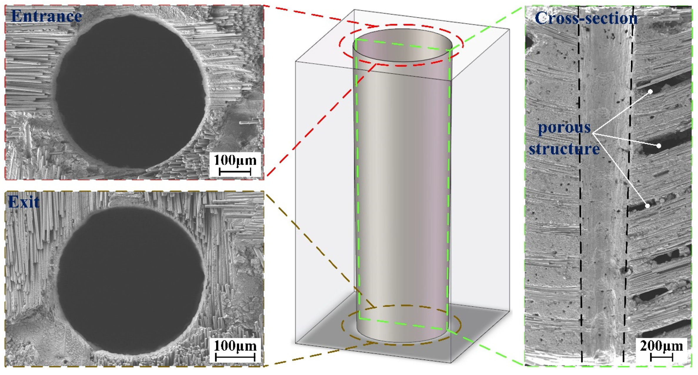
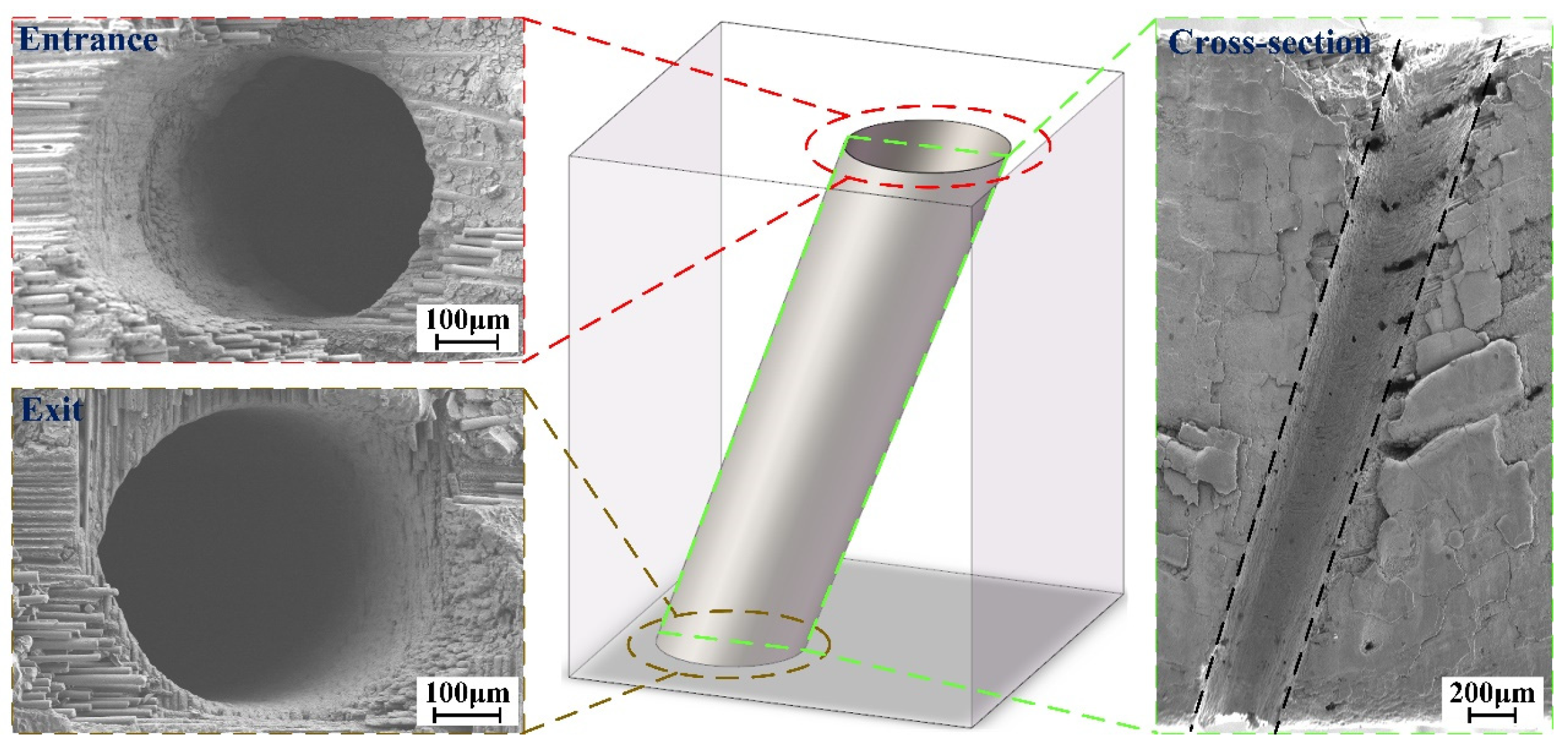
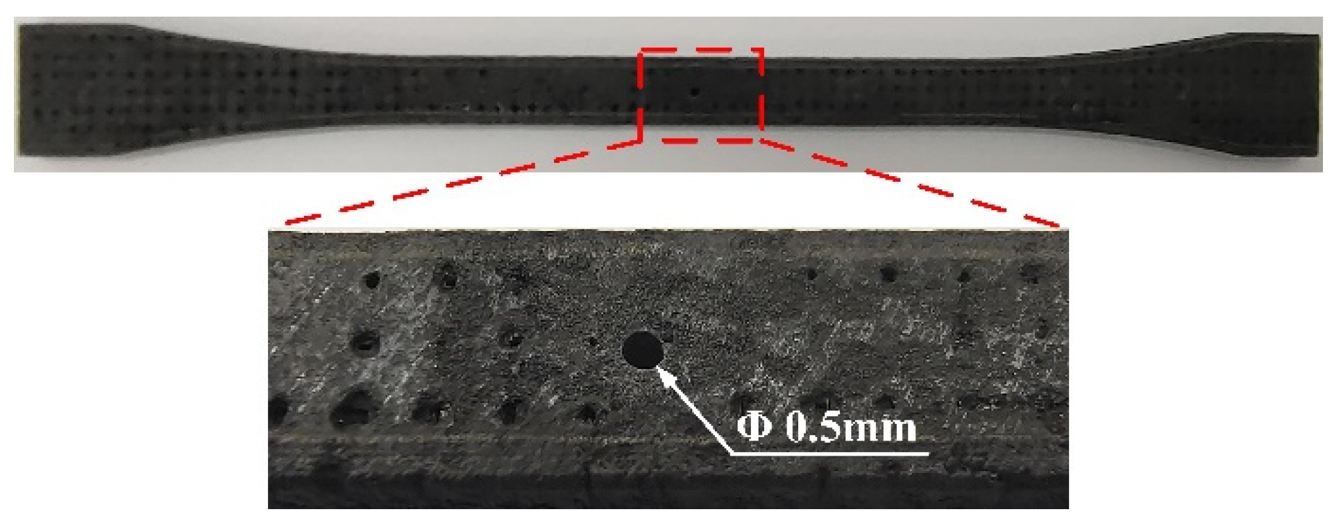
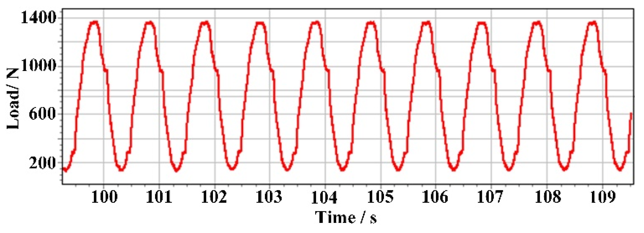
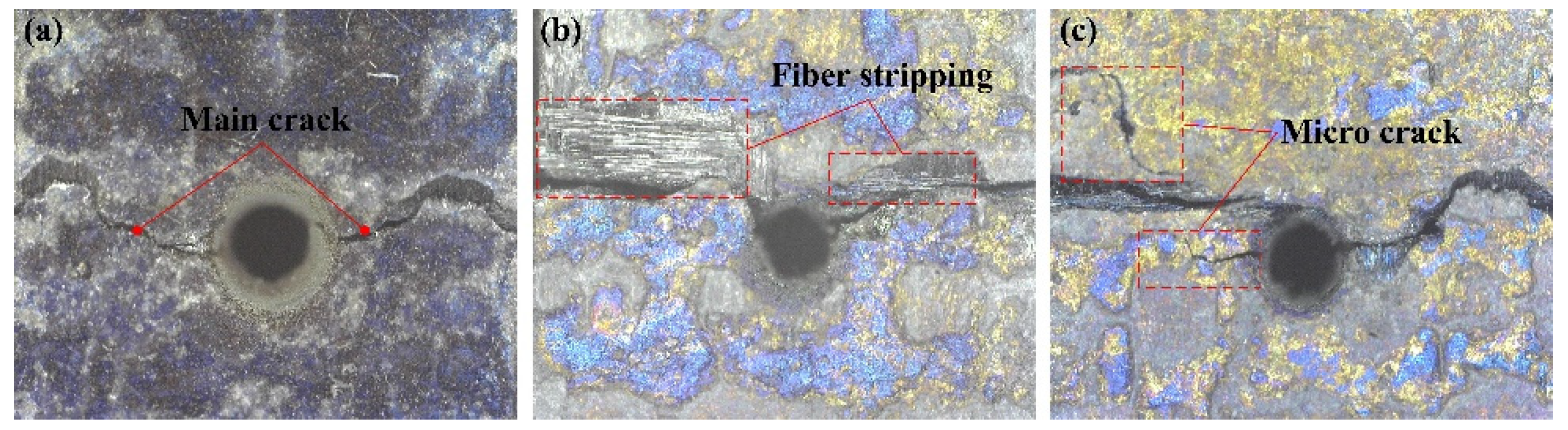
4.3. Layer-by-Layer Inside-Out CAAAWJGL Concentric-Circle Drilling and Tensile Tests
4.4. Further Application of CAAAWJGL on Scribing CVD Diamond
5. Conclusions
- (1)
- The introduction of coaxial annulus argon atmospheres proactively interrupts the water jet, leading to a decrease in the working length. Nevertheless, compared to the utilization of a coaxial helical atmosphere, the CAAAWJGL beam exhibits superior maintenance of its core velocity within the constrained working length, therefore enhancing the processing capability. This enhancement is manifested in a single row scribing depth-to-width ratio of 41.2, representing a noteworthy improvement of 57.84% and 32.96% compared to ambient conditions and a helical atmosphere, respectively.
- (2)
- The modification of the CAAAWJGL beam improves the ablation capacity of single-point percussion drilling on CMCs, obtaining a maximum depth-to-diameter ratio of 40.7. Furthermore, by employing an inside-out strategy, the successful fabrication of vertical and inclined holes is accomplished with exceptional circularity at both the entrance and exit, minimal taper, and negligible fiber drawing and delamination. The CAAAWJGL exhibits superior processing efficiency compared to femtosecond and picosecond lasers, meanwhile achieving a better tensile strength and fatigue life. Furthermore, the feasibility of CAAAWJGL machining is demonstrated through the scribing of CVD diamond with good perpendicularity and minimal defects on CVD diamond.
Supplementary Materials
Author Contributions
Funding
Institutional Review Board Statement
Informed Consent Statement
Data Availability Statement
Conflicts of Interest
References
- Doi, T. Next-generation, super-hard-to-process substrates and their high-efficiency machining process technologies used to create innovative devices. Int. J. Autom. Technol. 2018, 12, 145–153. [Google Scholar] [CrossRef]
- Axinte, D.; Billingham, J.; Bilbao, G.A. New models for energy beam machining enable accurate generation of free forms. Sci. Adv. 2017, 3, e1701201. [Google Scholar] [CrossRef] [Green Version]
- Lu, M.Y.; Zhang, M.; Zhang, K.H.; Meng, Q.G.; Zhang, X.Q. Femtosecond UV laser ablation characteristics of polymers used as the matrix of astronautic composite material. Materials 2022, 15, 6771. [Google Scholar] [CrossRef]
- Richerzhagen, B.; Kutsuna, M.; Okada, H.; Ikeda, T. Water-jet-guided laser processing. Proc. SPIE 2003, 4830, 91–94. [Google Scholar] [CrossRef]
- Sun, D.; Han, F.Z.; Ying, W.S. The experimental investigation of water jet–guided laser cutting of CFRP. Int. J. Adv. Manuf. Technol. 2019, 102, 719–729. [Google Scholar] [CrossRef]
- Marimuthu, S.; Dunleavey, J.; Liu, Y.; Smith, B.; Kiely, A.; Antar, M. Water-jet guided laser drilling of SiC reinforced aluminium metal matrix composites. J. Compos. Mater. 2019, 53, 3787–3796. [Google Scholar] [CrossRef]
- Marimuthu, S.; Smith, B. Water-jet guided laser drilling of thermal barrier coated aerospace alloy. Int. J. Adv. Manuf. Technol. 2021, 113, 177–191. [Google Scholar] [CrossRef]
- Liao, Z.; Xu, D.; Axinte, D.; Diboine, J.; Wretland, A. Surface formation mechanism in waterjet guided laser cutting of a Ni-based superalloy. CIRP Ann. 2021, 70, 155–158. [Google Scholar] [CrossRef]
- Cheng, B.; Ding, Y.; Li, Y.; Li, J.Y.; Xu, J.J.; Li, Q.; Yang, L.J. Coaxial helical gas assisted laser water jet machining of SiC/SiC ceramic matrix composites. J. Mater. Process. Technol. 2021, 293, 117067. [Google Scholar] [CrossRef]
- Nektarios, K.; John, G.B.; Nicolas, C.M. Evaluation of Reynolds stress, k-ε and RNG k-ε turbulence models in street canyon flows using various experimental datasets. Environ. Fluid Mech. 2012, 12, 379–403. [Google Scholar] [CrossRef]
- Yakhot, V.; Orszag, S.A.; Thangam, S.; Gatski, T.B.; Speziale, C.G. Development of turbulence models for shear flows by a double expansion technique. Phys. Fluids A Fluid Dyn. 1992, 4, 1510–1520. [Google Scholar] [CrossRef] [Green Version]
- Lasheras, J.C.; Hopfinger, E.J. Liquid jet instability and atomization in a coaxial gas stream. Annu. Rev. Fluid Mech. 2000, 32, 275–308. [Google Scholar] [CrossRef]
- Clanet, C.; Lasheras, J.C. Depth of penetration of bubbles entrained by a plunging water jet. Phys. Fluids 1997, 9, 1864–1866. [Google Scholar] [CrossRef] [Green Version]
- Chigier, N.A.; Beer, J.M. Velocity and static pressure distributions in swirling air jets issuing form annular and divergent nozzles. J. Basic Eng. 1964, 86, 788–798. [Google Scholar] [CrossRef]
- Yang, M.G.; Gong, C.; Wang, Y.L.; Lu, J.G. Experimental study of ultra-high pressure capillary water jet based on image intensity. J. Propuls. Technol. 2014, 35, 87–92. [Google Scholar] [CrossRef]
- Yang, L.J.; Ding, Y.; Wang, M.L.; Cao, T.T.; Wang, Y. Numerical and experimental investigations on 342 nm femtosecond laser ablation of K24 superalloy. J. Mater. Process. Technol. 2017, 249, 14–24. [Google Scholar] [CrossRef]
- Available online: https://www.antpedia.com/standard/5788433.html (accessed on 7 August 2023).
- Oriol, G.D.; Gonzalo, G.L.; Liao, Z.R.; Dragos, A. The new challenges of machining ceramic matrix composites (CMCs): Review of surface integrity. Int. J. Mach. Tools Manuf. 2019, 139, 24–36. [Google Scholar] [CrossRef]
- Zhai, Z.Y.; Wei, C.; Zhang, Y.C.; Cui, Y.H.; Zeng, Q.R. Investigations on the oxidation phenomenon of SiC/SiC fabricated by high repetition frequency femtosecond laser. Appl. Surf. Sci. 2020, 502, 144131. [Google Scholar] [CrossRef]
- Li, Y.; Ding, Y.; Cheng, B.; Cao, J.J.; Yang, L.J. Numerical and experimental research on the laser-water jet scribing of silicon. Appl. Sci. 2022, 12, 4057. [Google Scholar] [CrossRef]
- Villermaux, E.; Rehab, H.; Hopfinger, E.J. Breakup regimes and self-sustained pulsations in coaxial jets. Meccanica 1994, 29, 393–401. [Google Scholar] [CrossRef]
- Rehab, H.; Villermaux, E.; Hopfinger, E.J. Flow regimes of large-velocity-ratio coaxial jets. J. Fluid Mech. 1997, 345, 357–381. [Google Scholar] [CrossRef]


| Parameter | Wavelength | Pulse Duration | Repetition Rate | Average Power | Pulse Energy | M2 |
|---|---|---|---|---|---|---|
| Value | 532 nm | 100–120 ns | 50–100 kHz | 50 W (max) | 1 mJ (max) | 12 |
| Pulse Energy | Repetition Rate | Scribing Velocity | Scribing Time |
|---|---|---|---|
| 1 mJ | 50 kHz | 10 mm/s | 200 |
| Water Pressure/MPa | Pulse Energy/mJ | Repetition Rate/kHz | Drilling Time/s |
|---|---|---|---|
| 10, 15, 20, 25, 30 | 0.1, 0.2, 0.4, 0.6, 0.8, 1.0 | 50 | 60 |
| Parameter | RE/μm | d/μm | r/μm | l/μm | Layer Number |
| Value | 210 | 30 | 30 | 505 | 6 |
| Argon pressure /MPa | Repetition rate /kHz | External working length /mm | Pulse energy /mJ | Path scanning velocity/mm·s−1 | Drilling time/s |
| 0.7 | 50 | 12 | 1.0 | 10 | 67 |
| Hole Number | 1 | 2 | 3 | 4 | 5 | Average |
|---|---|---|---|---|---|---|
| Entrance diameter/μm | 493.5 | 487.8 | 491.1 | 490.7 | 488.9 | 490.4 |
| Entrance circularity/μm | 3.5 | 4.2 | 4.1 | 3.6 | 4.1 | 3.9 |
| Exit diameter/μm | 385.6 | 383.5 | 386.9 | 386.5 | 385.5 | 385.6 |
| Exit circularity/μm | 5.3 | 5.2 | 4.9 | 4.6 | 4.5 | 4.9 |
| Taper | 0.0163 | 0.0158 | 0.0158 | 0.0158 | 0.0157 | 0.0159 |
| Depth-to-diameter ratio | 6.69 | 6.77 | 6.72 | 6.73 | 6.75 | 6.73 |
| Hole Number | 6 | 7 | 8 | 9 | 10 | Average |
|---|---|---|---|---|---|---|
| Entrance diameter/μm | 498.5 | 499.3 | 498.1 | 497.9 | 498.7 | 498.5 |
| Entrance circularity/μm | 4.2 | 5.1 | 4.8 | 4.7 | 3.2 | 4.4 |
| Exit diameter/μm | 416.5 | 424.6 | 417.5 | 416.8 | 425.1 | 420.1 |
| Exit circularity/μm | 5.6 | 4.8 | 5.2 | 5.5 | 4.4 | 5.1 |
| Taper | 0.0124 | 0.0113 | 0.0122 | 0.0123 | 0.0112 | 0.0119 |
| Depth-to-diameter ratio | 6.62 | 6.61 | 6.63 | 6.63 | 6.62 | 6.62 |
| Parameter | RE/ Μm | d/ μm | r/ μm | l/ μm | Layer Number | Wavelength/nm |
| Laser | ||||||
| Femtosecond | 230 | 30 | 20 | 165 | 20 | 1030 |
| Picosecond | 230 | 30 | 20 | 165 | 20 | 343 |
| Parameter | Pulse duration/fs | Pulse energy /μJ | Repetition rate /kHz | Path scanning time | Path scanning velocity/mm·s−1 | Drilling time/s |
| Laser | ||||||
| Femtosecond | 255 | 400 | 37.5 | 400 | 150 | 87 |
| Picosecond | 8500 | 75 | 300 | 1100 | 400 | 95 |
| Machining Approach | Specimen 1/MPa | Specimen 2/MPa | Specimen 3/MPa | Specimen 4/MPa | Specimen 5/MPa | Average /MPa |
|---|---|---|---|---|---|---|
| CAAAWJGL | 198 | 237 | 209 | 214 | 205 | 212.6 |
| Femtosecond | 212 | 182 | 177 | 202 | 198 | 194.2 |
| Picosecond | 183 | 217 | 206 | 185 | 202 | 198.6 |
| Machining Approach | Specimen 1 | Specimen 2 | Specimen 3 | Specimen 4 | Specimen 5 | Average |
|---|---|---|---|---|---|---|
| CAAAWJGL/s | 90,854 | 87,621 | 91,215 | 89,541 | 88,448 | 89,463.8 |
| Femtosecond/s | 74,510 | 71,362 | 70,651 | 73,021 | 73,857 | 72,680.2 |
| Picosecond/s | 79,954 | 81,825 | 77,514 | 78,659 | 80,305 | 80,451.4 |
| Water Pressure/MPa | Argon Pressure /MPa | Repetition Rate /kHz | External Working Length /mm | Scribing Interval on the Same Layer/μm | Scribing Layer along Depth | Pulse Energy /mJ | Path Scanning Velocity/mm·s−1 |
|---|---|---|---|---|---|---|---|
| 30 | 0.7 | 50 | 16 | 20 | 50 | 1.0 | 20 |
| Groove Number | 1 | 2 | 3 | 4 | 5 | Average |
|---|---|---|---|---|---|---|
| Width/μm | 177.8 | 173.4 | 173.7 | 176.8 | 177.3 | 175.8 |
| Depth/μm | 2030.5 | 2042.6 | 2035.8 | 2032.2 | 2008.9 | 2030.0 |
Disclaimer/Publisher’s Note: The statements, opinions and data contained in all publications are solely those of the individual author(s) and contributor(s) and not of MDPI and/or the editor(s). MDPI and/or the editor(s) disclaim responsibility for any injury to people or property resulting from any ideas, methods, instructions or products referred to in the content. |
© 2023 by the authors. Licensee MDPI, Basel, Switzerland. This article is an open access article distributed under the terms and conditions of the Creative Commons Attribution (CC BY) license (https://creativecommons.org/licenses/by/4.0/).
Share and Cite
Li, Y.; Wang, S.; Ding, Y.; Cheng, B.; Xie, W.; Yang, L. Investigation on the Coaxial-Annulus-Argon-Assisted Water-Jet-Guided Laser Machining of Hard-to-Process Materials. Materials 2023, 16, 5569. https://doi.org/10.3390/ma16165569
Li Y, Wang S, Ding Y, Cheng B, Xie W, Yang L. Investigation on the Coaxial-Annulus-Argon-Assisted Water-Jet-Guided Laser Machining of Hard-to-Process Materials. Materials. 2023; 16(16):5569. https://doi.org/10.3390/ma16165569
Chicago/Turabian StyleLi, Yuan, Shuiwang Wang, Ye Ding, Bai Cheng, Wanda Xie, and Lijun Yang. 2023. "Investigation on the Coaxial-Annulus-Argon-Assisted Water-Jet-Guided Laser Machining of Hard-to-Process Materials" Materials 16, no. 16: 5569. https://doi.org/10.3390/ma16165569
APA StyleLi, Y., Wang, S., Ding, Y., Cheng, B., Xie, W., & Yang, L. (2023). Investigation on the Coaxial-Annulus-Argon-Assisted Water-Jet-Guided Laser Machining of Hard-to-Process Materials. Materials, 16(16), 5569. https://doi.org/10.3390/ma16165569