
Study of the Mineralogical Composition of an Alumina–Silica Binder System Formed by the Sol–Gel Method


Abstract
1. Introduction
2. Experimental Procedure
2.1. Raw Materials and Mixtures, Sample Preparation
2.2. Methods
3. Results and Discussion
3.1. First Stage
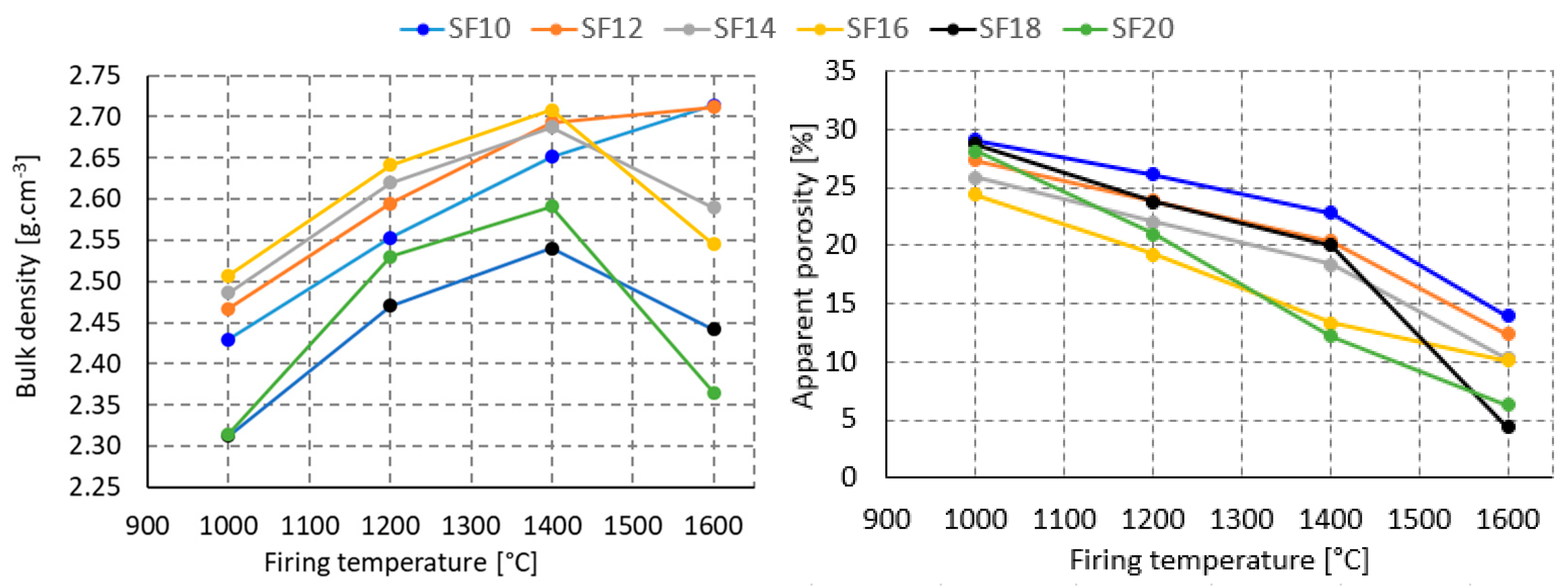
3.2. Second Stage
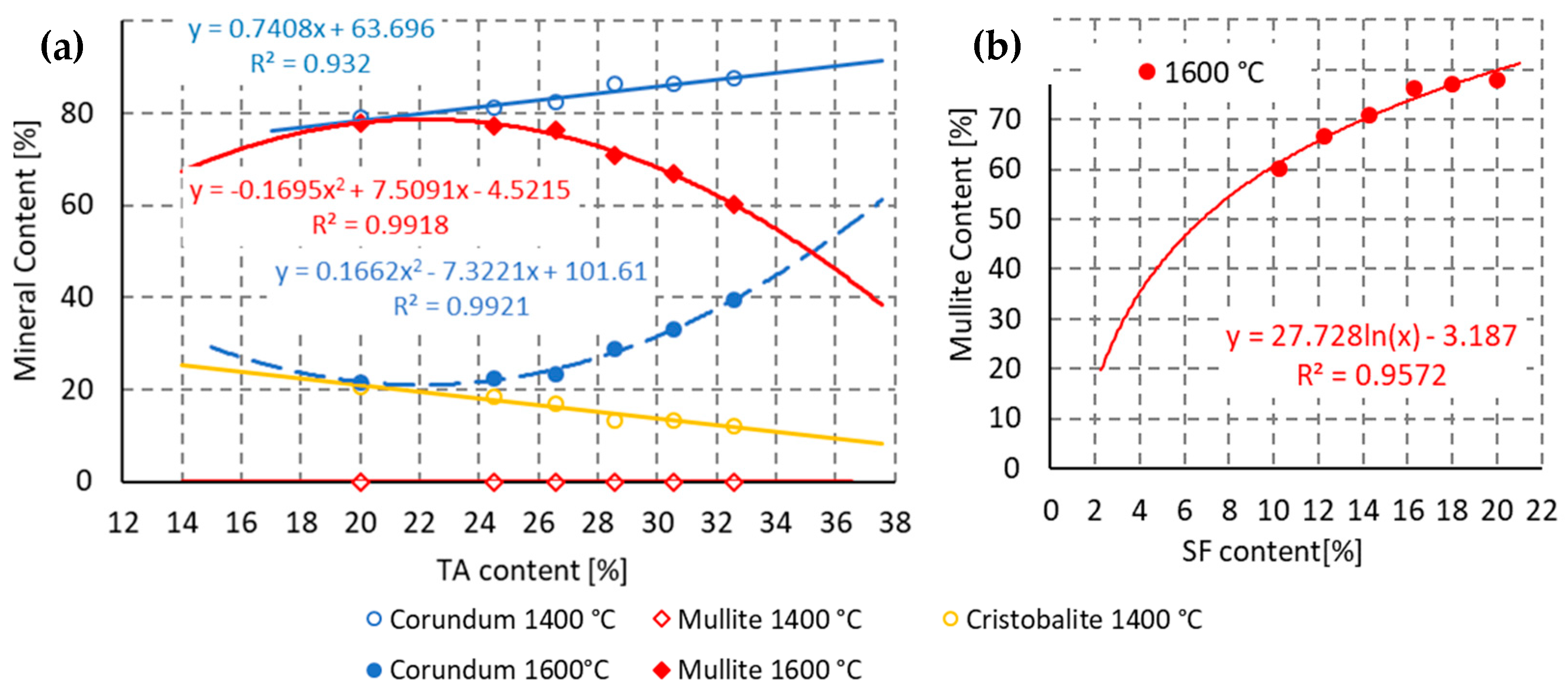
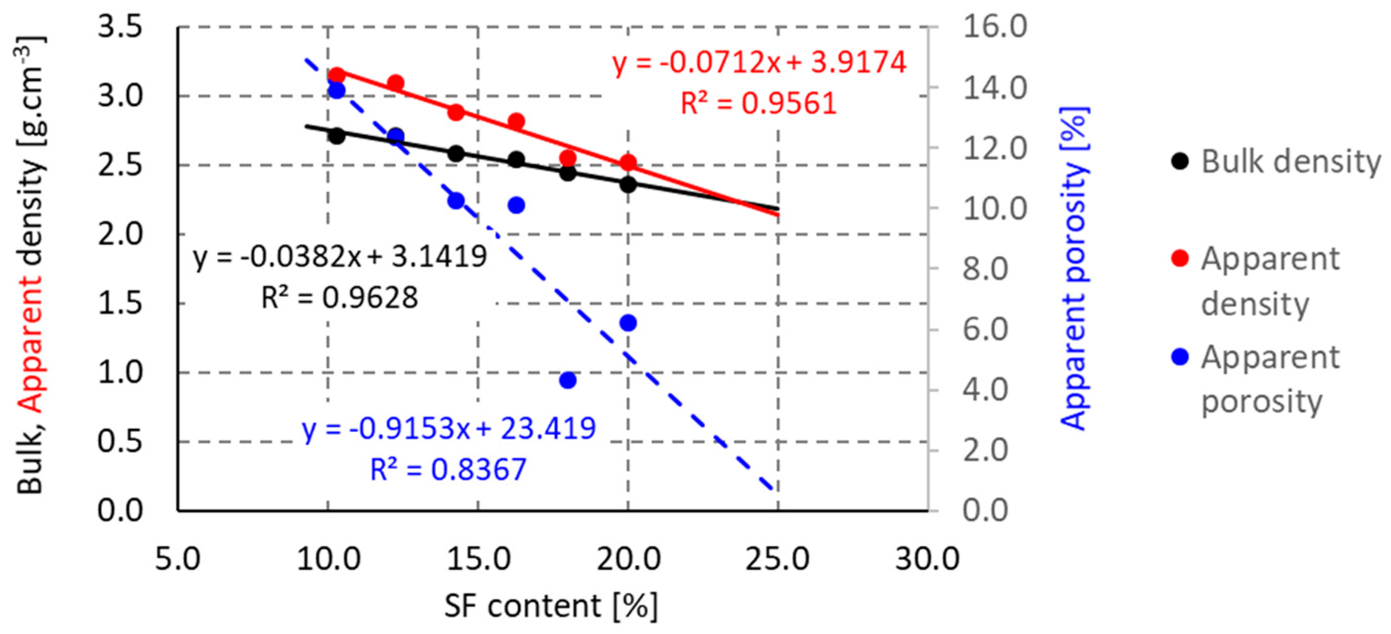
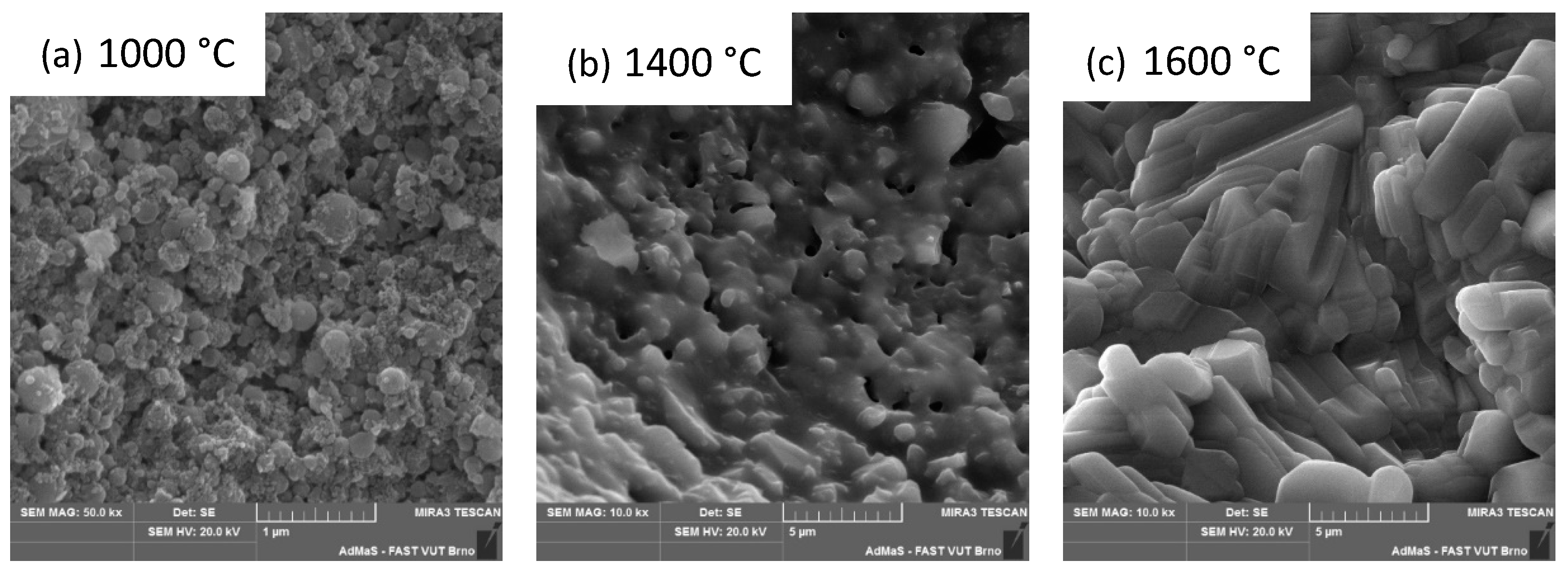
3.3. Third Stage
4. Conclusions
Author Contributions
Funding
Institutional Review Board Statement
Informed Consent Statement
Data Availability Statement
Conflicts of Interest
References
- Hewlett, P.; Liska, M. Lea’s Chemistry of Cement and Concrete; Butterworth-Heinemann: Oxford, UK, 2019. [Google Scholar]
- Schacht, C.A. Refractories Handbook; Taylor & Francis Inc.: Boca Raton, FL, USA, 2004. [Google Scholar]
- Banerjee, S. Monolithic Refractories: A Comprehensive Handbook; World Scientific: Singapore; American Ceramic Society: Columbus, OH, USA, 1998. [Google Scholar]
- Brinker, C.; Scherer, G. Sol-Gel Science: The Physics and Chemistry of Sol-Gel Processing; Academic Press: Cambridge, MA, USA, 1990. [Google Scholar]
- Levy, D.; Zayat, M. The Sol-Gel Handbook; John Wiley & Sons, Inc.: Hoboken, NJ, USA, 2015. [Google Scholar]
- Mukhopadhay, S.; Ghosh, S.; Mahapatra, M.K.; Majumdar, R.; Barick, P.; Gupta, S.; Chakraborty, S. Easy-to-use mullite and spinel sols as bonding agents in a high alumina based ultra low cement castable. Ceram. Int. 2002, 28, 719–729. [Google Scholar] [CrossRef]
- Ismael, M.R.; Salomao, R.; Pandolfelli, V.C. Colloidal Silica Bonded Refractory Castables: Optimization of the Particle Size Distribution. Refractories Application and News, January 2008; pp. 10–15. [Google Scholar]
- Ismael, M.R.; Pandolfelli, V.C. Refractory Castable Based on Colloidal Silica and Hydratable Alumina. Am. Ceram. Soc. Bull. 2002, 86, 58. [Google Scholar]
- Nishikawa, A. Technology of Monolithic Refractories; Plibrico Japan Company Limited: Tokyo, Japan, 1984; pp. 67–71. [Google Scholar]
- Nouri-Khezrabad, M.; Braulio, M.A.L.; Pandolfelli, V.C.; Golestani, F.; Rezaie, H.R. Nano-bonded refractory castables. Ceram. Int. 2013, 39, 3479–3497. [Google Scholar] [CrossRef]
- Bayoumi, I.M.I.; Ewais, E.M.M.; El-Amir, A.A.M. Rheology of refractory concrete. Boletín Soc. Española Cerámica Vidr. 2021, 61, 453–469. [Google Scholar] [CrossRef]
- Anjos, R.D.; Ismael, M.R.; Oliveria, I.R.; Pandolfelli, V.C. Workability and Setting Parameters Evolution of Colloidal Silica Bonded Refractory Suspension. Ceram. Int. 2008, 34, 165–171. [Google Scholar] [CrossRef]
- Nouri-Khezrabad, M.; Salvini, V.R.; Luz, A.P.; Golestani-Fard, F.; Rezaie, H.R.; Pandolfelli, V.C. Rheological performance of high alumina nano-bonded refractory castables containing carboxylic acids as additives. Ceram. Int. 2015, 41, 11251–11256. [Google Scholar] [CrossRef]
- Peng, H.; Myhre, B. Microsilica-Gel Bonded Refractory Castables with Improved Set-Behaviour and Mechanical Properties. Refract. WorldForum 2015, 7, 69–75. [Google Scholar]
- Luz, A.P.; Moreira, M.H.; Parr, C.; Pandolfelli, V.C. Drying behavior of dense refractory ceramic castables. Part 1—General aspects and experimental techniques used to assess water removal. Ceram. Int. 2021, 47, 22246–22268. [Google Scholar] [CrossRef]
- Luz, A.P.; Moreira, M.H.; Salomão, R.; Braulio, M.A.L.; Pandolfelli, V.C. Drying behavior of dense refractory castables. Part 2—Drying agents and design of heating schedules. Ceram. Int. 2022, 48, 2965–2987. [Google Scholar] [CrossRef]
- Sarkar, R. Binders for Refractory Castables: An Overview. Interceram. Int. Ceram. Rev. 2020, 69, 44–53. [Google Scholar] [CrossRef]
- Banerjee, S. Recent developments in monolithic refractories. Am. Ceram. Soc. Bull. 1998, 77, 59–63. [Google Scholar]
- Oliveira, R.; Studart, A.R.; Pileggi, R.G.; Pandolfelli, V.C. Dispersion and Packing of Particles—Basic Principles and Applications to Ceramic Processing; Fazendo Arte Editorial: Brasília, Brazil, 2000. (In Portuguese) [Google Scholar]
- Nguyen, M.; Sokolář, R. Formation and Influence of Magnesium-Alumina Spinel on Properties of Refractory Forsterite-Spinel Ceramics. Mater. Tehnol. 2020, 54, 135–141. [Google Scholar] [CrossRef]
- Jiancheng, A.; Wang, Y.; Jia, Q.; Zhao, F.; Liu, X. Microstructure and reactivity evolution of colloidal silica binder in different systems at elevated temperatures. Ceram. Int. 2020, 46, 20129–20137. [Google Scholar]
- Singh, A.K.; Sarkar, R. High alumina castables: A comparison among various sol-gel bonding systems. J. Aust. Ceram. Soc. 2017, 53, 553–567. [Google Scholar] [CrossRef]
- Yaghoubi, H.; Sarpoolaky, H.; Golestanifard, F.; Souri, A. Influence of nano silica on properties and microstructure of high alumina ultra-low cement refractory castables. Iran. J. Mater. Sci. Eng. 2012, 9, 50–58. [Google Scholar]
- Bareiro, W.G.; Silva, F.A.; Sotelino, E.D.; Gomes, O.F.M. The influence of alumina content on the chemical and mechanical behavior of refractory concretes fired at different temperatures. Constr. Build. Mater. 2018, 187, 1214–1223. [Google Scholar] [CrossRef]
- Zawrah, M.F.M.; Khalil, N.M. Effect of Mullite Formation on Properties of Refractory Castables. Ceram. Int. 2007, 27, 689–694. [Google Scholar] [CrossRef]
- Myhre, B. Let’s Make Mullite Matrix. Refract. Appl. News 2008, 13, 11–19. [Google Scholar]
- Ismael, M.R.; Salomao, R.; Pandolfelli, V.C. Optimization of silica sol application as a binder for refractory castables. Cerâmica 2006, 52, 321. (In Portuguesse) [Google Scholar] [CrossRef]
- Sacks, M.D.; Wang, K.; Scheiffele, G.W.; Bozkurt, N. Effect of Composition on Mullitization Behavior of α-Alumina/Silica Microcomposite Powders. J. Am. Ceram. Soc. 1997, 80, 663–672. [Google Scholar] [CrossRef]
- Sacks, M.D.; Bozkurt, N.; Scheiffele, G.W. Fabrication of Mullite and Mullite-Matrix Composition by Transient Viscous Sintering of Composite Powders. J. Am. Ceram. Soc. 1991, 74, 2428–2437. [Google Scholar] [CrossRef]
- Pask, J.A.; Zhang, X.W.; Tomasia, A.P. Effect of Sol-Gel Mixing on Mullite Microstructure and Phase Equilibria in the α-Al2O3-SiO2 System. J. Am. Ceram. Soc. 1997, 70, 704–707. [Google Scholar] [CrossRef]
- Bokov, D.; Jalil, A.T.; Chupradit, S.; Suksatan, W.; Ansari, M.J.; Shewael, I.H.; Valiev, G.H.; Kianfar, E. Nanomaterial by Sol-Gel Method: Synthesis and Application. Adv. Mater. Sci. Eng. 2021, 2021, 5102014. [Google Scholar] [CrossRef]
- MacZura, G.; Goodboy, K.R.; Koenig, J.J. Aluminum Compounds (Aluminum Oxides) in Kirk-Othmer Encyclopedia of Chemical Technology, 3rd ed.; Wiley: New York, NY, USA, 1987; Volume 2, pp. 218–244. [Google Scholar]
- Lee, W.E.; Kelly, A.; Zweben, C. Comprehensive Composite Materials. Pergamon Oxf. 2000, 2, 20–21. [Google Scholar] [CrossRef]
- Gürel, S.B.; Altun, A. Reactive alumina production for the refractory industry. Powder Technol. 2009, 196, 115–121. [Google Scholar] [CrossRef]
- EN 993-5:2018; Methods of Test for Dense Shaped Refractory Products—Part 5: Determination of Cold Crushing Strength. European Standard: Pilsen, Czech Republic, 2018.
- EN 993-6:2018; Methods of Test for (Dense) Shaped Refractory Products—Part 6: Determination of Modulus of Rupture at Ambient Temperature. European Standard: Pilsen, Czech Republic, 2018.
- EN 993-1:2018; Methods of Test for Dense Shaped Refractory Products—Part 1: Determination of Bulk Density, Apparent Porosity and True Porosity. European Standard: Pilsen, Czech Republic, 2018.
- EN 993-10:2020; Methods of Test for Dense Shaped Refractory Products—Part 10: Determination of Permanent Change in Dimensions on Heating. European Standard: Pilsen, Czech Republic, 2020.
- Wang, L.S.; Bor, J.T. The sintering and crystallization of colloidal silica gel. Mater. Lett. 2000, 43, 309–314. [Google Scholar] [CrossRef]
- Braga, A.; Duarte-Neto, J.; Menezes, R.; Lira, H.; Neves, G. Synthesis of mullite by the sol-gel process: A literature review. Rev. Eletr. Mater. e Proc. 2014, 9, 60–73. (In Portuguese) [Google Scholar]
- Okada, K.; Otsuka, N. Characterization of the Spinel Phase from SiO2-Al2O3 Xerogels and the Formation Process of Mullite. J. Am. Ceram. Soc. 1986, 69, 652–656. [Google Scholar] [CrossRef]


| Chemical Composition | TA | GA | RA1 | RA2 | SF |
|---|---|---|---|---|---|
| SiO2 | 0.09 | 0.80 | 0.16 | 0.12 | 98.46 |
| Al2O3 | 99.55 | 98.35 | 99.45 | 99.53 | 0.04 |
| TiO2 | – | 0.03 | – | – | 0.01 |
| Fe2O3 | 0.01 | 0.09 | – | – | 0.07 |
| CaO | – | 0.22 | 0.01 | 0.01 | 0.62 |
| MgO | – | 0.23 | 0.14 | 0.17 | 0.04 |
| K2O | – | 0.03 | 0.04 | 0.08 | 0.55 |
| Na2O | 0.45 | 0.25 | 0.20 | 0.09 | 0.01 |
| Phase composition | |||||
| Quartz | – | – | – | – | 0.26 |
| Corundum | 94.98 | 98.90 | 100 | 100 | – |
| Andalusite | – | – | – | – | – |
| Diaoyudaoite | 5.02 | 1.10 | – | – | – |
| Amorphous phase | – | – | – | – | 99.74 |
| Particle size (μm) | 0.5–10 | 1.0–10 | 0.5–10 | 1.0–10 | 0.15–0.2 |
| Raw Material | Sol (wt. %) | Gelling Time (s) |
|---|---|---|
| TA | 38.7 | 240 |
| GA | 42.2 | 230 |
| RA1 | 41.7 | 180 |
| RA2 | 39.0 | 180 |
| SF | 120.0 | 120 |
| Component (wt. %) | SF10 | SF12 | SF14 | SF16 | SF18 | SF20 |
|---|---|---|---|---|---|---|
| TA | 32.6 | 30.6 | 28.6 | 26.6 | 24.5 | 20.0 |
| GA | 21.1 | 19.9 | 17.9 | 15.9 | 26.0 | 20.0 |
| RA1 | 18.6 | 17.9 | 17.9 | 17.9 | 16.0 | 20.0 |
| RA2 | 17.4 | 19.4 | 21.4 | 23.4 | 15.5 | 20.0 |
| SF | 10.3 | 12.3 | 14.3 | 16.3 | 18.0 | 20.0 |
| Mineral Content (%) | ||||||||||
|---|---|---|---|---|---|---|---|---|---|---|
| 1200 °C | 1400 °C | 1600 °C | ||||||||
| Fine Matrix | Q | C | Cn | Q | C | Cn | Q | C | Cn | M |
| SF10 | 0.5 | 11.1 | 88.4 | 0.3 | 12 | 87.7 | 0 | 0.3 | 39.4 | 60.2 |
| SF12 | 0.3 | 13.5 | 86.2 | 0.3 | 13.4 | 86.3 | 0 | 0.3 | 32.9 | 66.7 |
| SF14 | 0.4 | 13.7 | 86 | 0.3 | 13.4 | 86.3 | 0 | 0.2 | 28.9 | 70.9 |
| SF16 | 1.2 | 15.8 | 83 | 0.6 | 17 | 82.3 | 0 | 0.2 | 23.4 | 76.4 |
| SF18 | 0.5 | 17.6 | 81.9 | 0.4 | 18.5 | 81.1 | 0 | 0.4 | 22.5 | 77.2 |
| SF20 | 0.6 | 19.3 | 80.2 | 0.4 | 20.6 | 79.1 | 0 | 0.5 | 21.6 | 77.9 |
Disclaimer/Publisher’s Note: The statements, opinions and data contained in all publications are solely those of the individual author(s) and contributor(s) and not of MDPI and/or the editor(s). MDPI and/or the editor(s) disclaim responsibility for any injury to people or property resulting from any ideas, methods, instructions or products referred to in the content. |
© 2023 by the authors. Licensee MDPI, Basel, Switzerland. This article is an open access article distributed under the terms and conditions of the Creative Commons Attribution (CC BY) license (https://creativecommons.org/licenses/by/4.0/).
Share and Cite
Nevřivová, L.; Zemánek, D. Study of the Mineralogical Composition of an Alumina–Silica Binder System Formed by the Sol–Gel Method. Materials 2023, 16, 5466. https://doi.org/10.3390/ma16155466
Nevřivová L, Zemánek D. Study of the Mineralogical Composition of an Alumina–Silica Binder System Formed by the Sol–Gel Method. Materials. 2023; 16(15):5466. https://doi.org/10.3390/ma16155466
Chicago/Turabian StyleNevřivová, Lenka, and David Zemánek. 2023. "Study of the Mineralogical Composition of an Alumina–Silica Binder System Formed by the Sol–Gel Method" Materials 16, no. 15: 5466. https://doi.org/10.3390/ma16155466
APA StyleNevřivová, L., & Zemánek, D. (2023). Study of the Mineralogical Composition of an Alumina–Silica Binder System Formed by the Sol–Gel Method. Materials, 16(15), 5466. https://doi.org/10.3390/ma16155466