
Effect of Current Density on the Corrosion Resistance and Photocatalytic Properties of Cu-Ni-Zn0.96Ni0.02Cu0.02O Nanocomposite Coatings

Abstract
1. Introduction
2. Experimental Materials and Methods
2.1. Synthesis of Zn0.96Ni0.02Cu0.02O Nanopowders
2.2. Preparation of Cu-Ni-Zn0.96Ni0.02Cu0.02O Nanocomposite Coatings
2.3. Characterization Techniques
3. Results
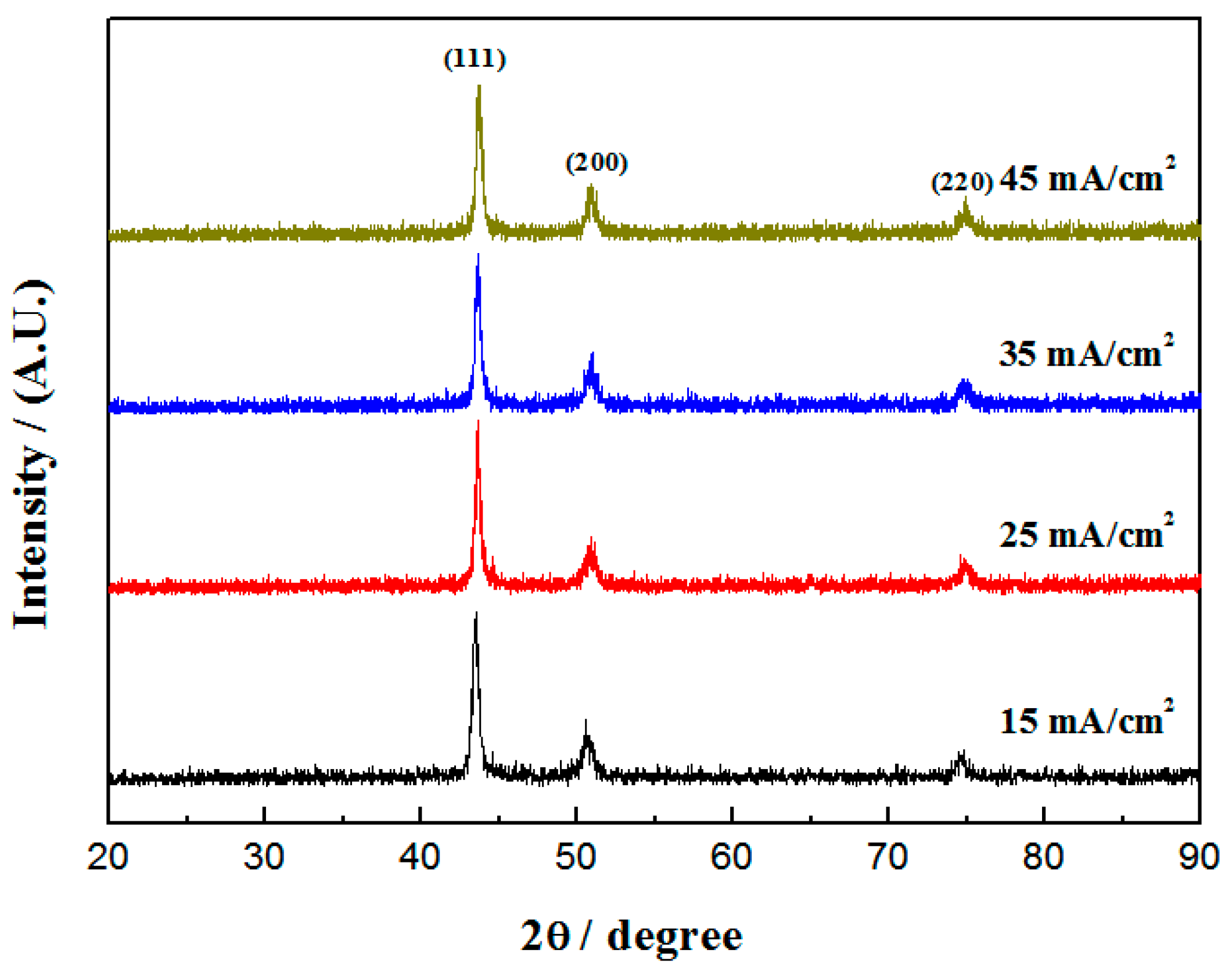
3.1. Phase Structure
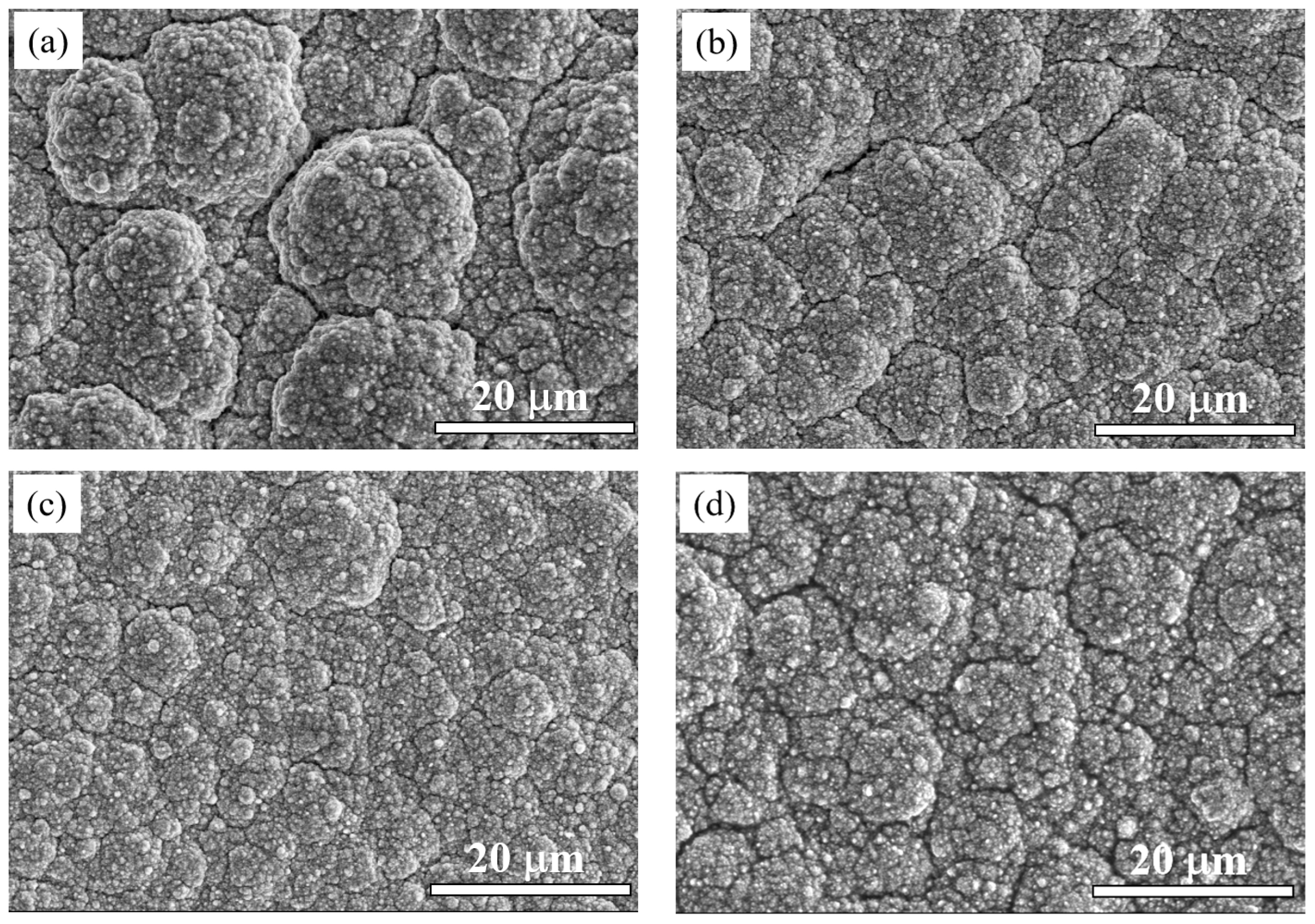
3.2. Surface Morphology
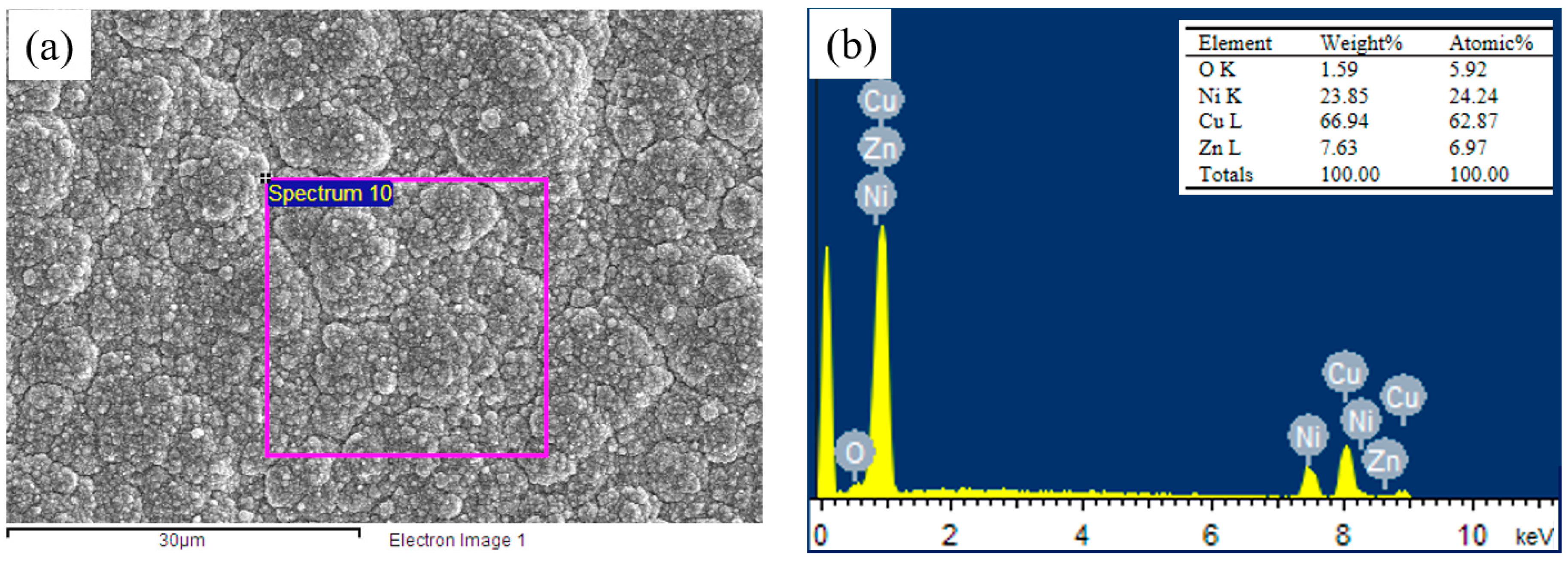
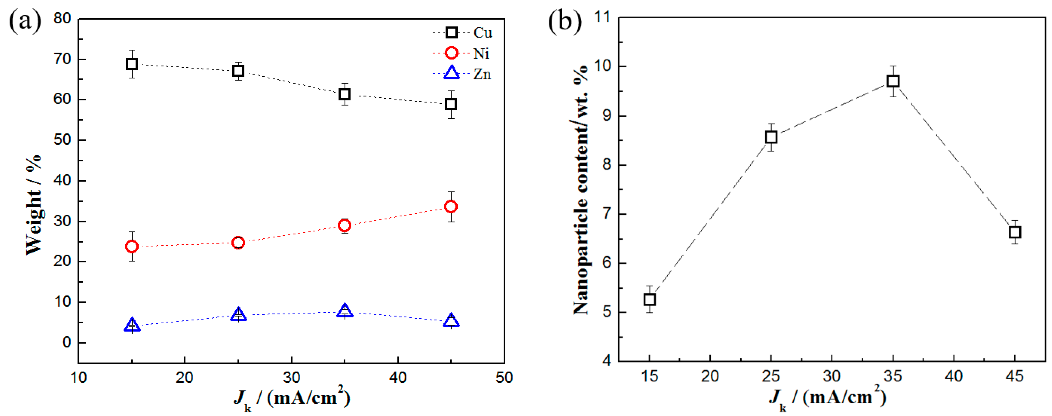
3.3. Composition
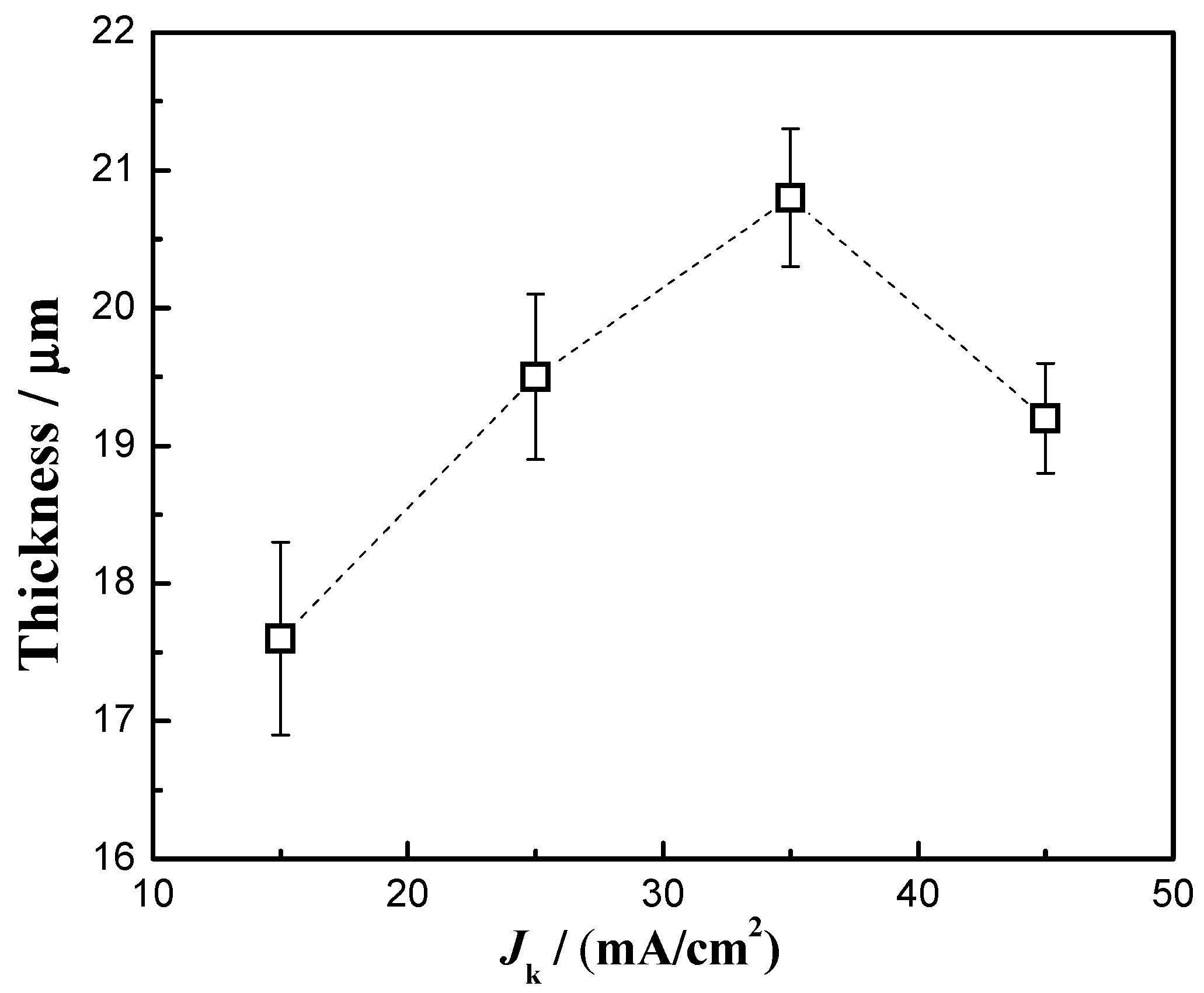
3.4. Thickness
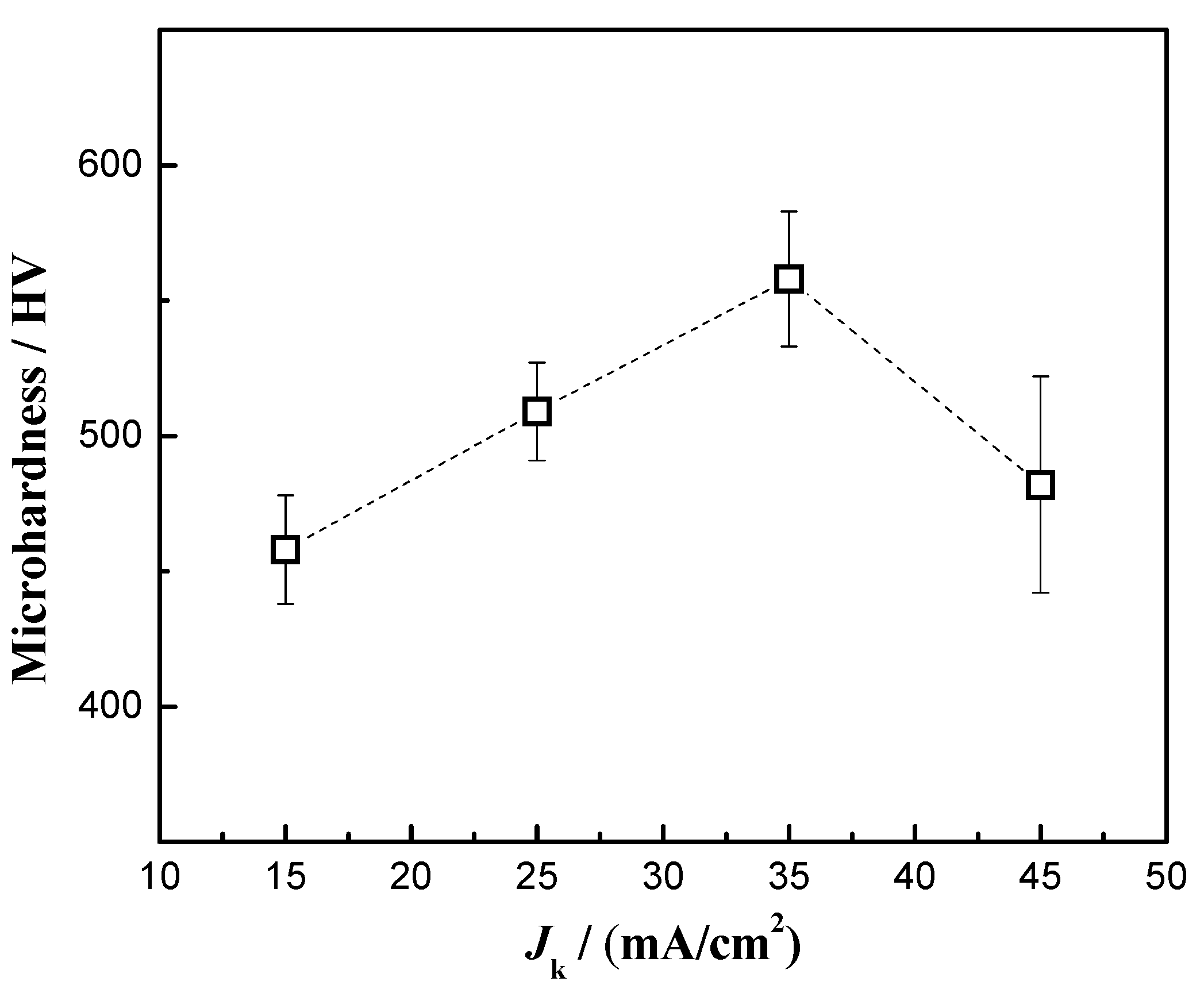
3.5. Microhardness
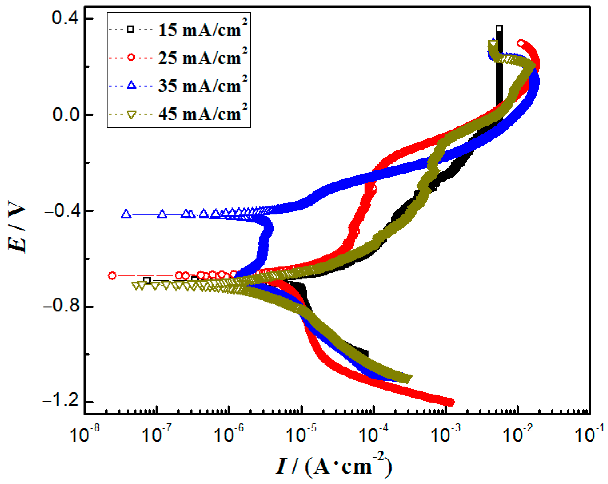
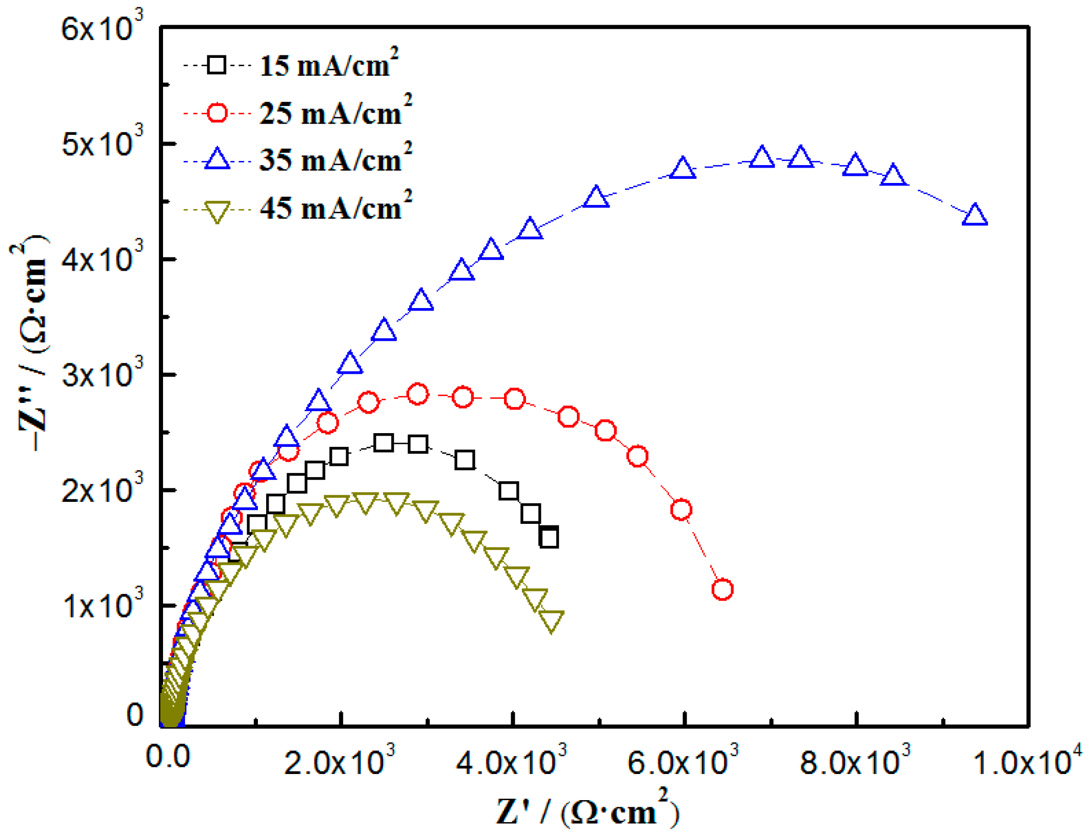
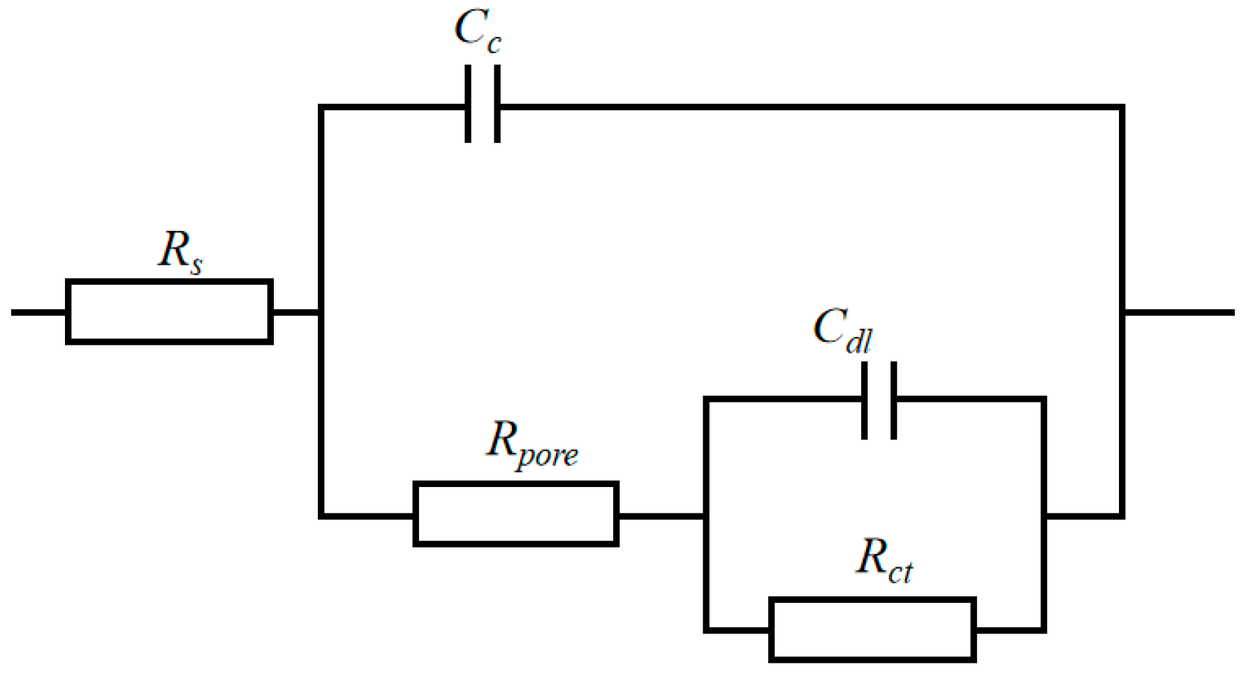
3.6. Corrosion Resistance
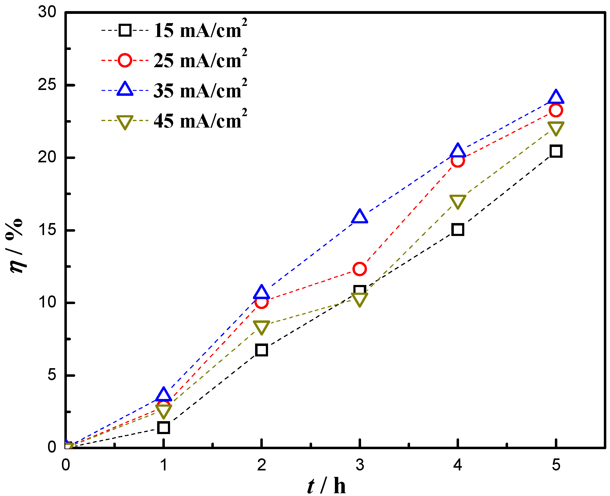
3.7. Photocatalytic Performance
4. Conclusions
Author Contributions
Funding
Institutional Review Board Statement
Informed Consent Statement
Data Availability Statement
Acknowledgments
Conflicts of Interest
References
- Zhao, Q.; Guo, C.; Niu, K.; Zhao, J.; Huang, Y.; Li, X. Long-term corrosion behavior of the 7A85 aluminum alloy in an industrial-marine atmospheric environment. J. Mater. Res. Technol. 2021, 12, 1350–1359. [Google Scholar] [CrossRef]
- Jiang, Q.; Lu, D.; Wang, N.; Wang, X.; Zhang, J.; Duan, J.; Hou, B. The corrosion behavior of Mg–Nd binary alloys in the harsh marine environment. J. Magnes. Alloys 2021, 9, 292–304. [Google Scholar] [CrossRef]
- Refait, P.; Grolleau, A.M.; Jeannin, M.; Rémazeilles, C.; Sabot, R. Corrosion of Carbon Steel in Marine Environments: Role of the Corrosion Product Layer. Corros. Mater. Degrad. 2020, 1, 198–218. [Google Scholar] [CrossRef]
- Lu, X.; Liu, Y.W.; Zhao, H.T.; Pan, C.; Wang, Z.Y. Corrosion behavior of copper in extremely harsh marine atmosphere in Nansha Islands, China. Trans. Nonferrous Met. Soc. China 2021, 31, 703–714. [Google Scholar] [CrossRef]
- Pingale, A.D.; Owhal, A.; Katarkar, A.S.; Belgamwar, S.U.; Rathore, J.S. Recent researches on Cu-Ni alloy matrix composites through electrodeposition and powder metallurgy methods: A review. Mater. Today Proc. 2021, 47, 3301–3308. [Google Scholar] [CrossRef]
- Deo, Y.; Guha, S.; Sarkar, K.; Mohanta, P.; Pradhan, D.; Mondal, A. Electrodeposited Ni-Cu alloy coatings on mild steel for enhanced corrosion properties. Appl. Surf. Sci. 2020, 515, 146078. [Google Scholar] [CrossRef]
- Alizadeh, M.; Safaei, H. Characterization of Ni-Cu matrix, Al2O3 reinforced nano-composite coatings prepared by electrodeposition. Appl. Surf. Sci. 2018, 456, 195–203. [Google Scholar] [CrossRef]
- Li, B.; Du, S.; Mei, T. Pulse electrodepsoited Ni-Cu/TiN-ZrO2 nanocomposite coating: Microstructural and electrochemical properties. Mater. Res. Express 2019, 6, 096433. [Google Scholar] [CrossRef]
- Li, B.; Mei, T.; Li, D.; Du, S. Ultrasonic-assisted electrodeposition of Ni-Cu/TiN composite coating from sulphate-citrate bath: Structural and electrochemical properties. Ultrason. Sonochem. 2019, 58, 104680. [Google Scholar] [CrossRef]
- Safavi, M.S.; Fathi, M.; Mirzazadeh, S.; Ansarian, A.; Ahadzadeh, I. Perspectives in corrosion-performance of Ni–Cu coatings by adding Y2O3 nanoparticles. Surf. Eng. 2021, 37, 226–235. [Google Scholar] [CrossRef]
- Pingale, A.D.; Belgamwar, S.U.; Rathore, J.S. Effect of graphene nanoplatelets addition on the mechanical, tribological and corrosion properties of Cu–Ni/Gr nanocomposite coatings by electro-co-deposition method. Trans. Indian Inst. Met. 2020, 73, 99–107. [Google Scholar] [CrossRef]
- Pascariu, P.; Tudose, I.V.; Suchea, M.; Koudoumas, E.; Fifere, N.; Airinei, A. Preparation and characterization of Ni, Co doped ZnO nanoparticles for photocatalytic applications. Appl. Surf. Sci. 2018, 448, 481–488. [Google Scholar] [CrossRef]
- Król, A.; Pomastowski, P.; Rafińska, K.; Railean-Plugaru, V.; Buszewski, B. Zinc oxide nanoparticles: Synthesis, antiseptic activity and toxicity mechanism. Adv. Colloid Interface Sci. 2017, 249, 37–52. [Google Scholar] [CrossRef]
- Ong, C.B.; Ng, L.Y.; Mohammad, A.W. A review of ZnO nanoparticles as solar photocatalysts: Synthesis, mechanisms and applications. Renew. Sustain. Energy Rev. 2018, 81, 536–551. [Google Scholar] [CrossRef]
- Saadi, H.; Benzarti, Z.; Sanguino, P.; Pina, J.; Abdelmoula, N.; de Melo, J.S.S. Enhancing the electrical conductivity and the dielectric features of ZnO nanoparticles through Co doping effect for energy storage applications. J. Mater. Sci. Mater. Electron. 2023, 34, 116. [Google Scholar] [CrossRef]
- Riaz, K.; Nadeem, S.; Chrouda, A.; Iqbal, S.; Mohyuddin, A.; Hassan, S.U.; Javed, M.; BaQais, A.; Tamam, N.; Aroosh, K.; et al. Coupling of Se-ZnFe2O4 with rGO for spatially charged separated nanocomposites as an efficient photocatalyst for degradation of organic pollutants in natural sunlight. Colloids Surf. A Physicochem. Eng. Asp. 2022, 649, 129332. [Google Scholar] [CrossRef]
- Sher, M.; Javed, M.; Shahid, S.; Hakami, O.; Qamar, M.A.; Iqbal, S.; Al-Anazy, M.M.; Baghdadi, H.B. Designing of highly active g-C3N4/Sn doped ZnO heterostructure as a photocatalyst for the disinfection and degradation of the organic pollutants under visible light irradiation. J. Photochem. Photobiol. A Chem. 2021, 418, 113393. [Google Scholar] [CrossRef]
- Senol, S.D.; Ozugurlu, E.; Arda, L. Synthesis, structure and optical properties of (Mn/Cu) co-doped ZnO nanoparticles. J. Alloys Compd. 2020, 822, 153514. [Google Scholar] [CrossRef]
- Guermat, N.; Daranfed, W.; Bouchama, I.; Bouarissa, N. Investigation of structural, morphological, optical and electrical properties of Co/Ni co-doped ZnO thin films. J. Mol. Struct. 2021, 1225, 129134. [Google Scholar] [CrossRef]
- Goktas, A. High-quality solution-based Co and Cu co-doped ZnO nanocrystalline thin films: Comparison of the effects of air and argon annealing environments. J. Alloys Compd. 2018, 735, 2038–2045. [Google Scholar] [CrossRef]
- Priya, R.; Sahay, P.; Saxena, N.; Rajput, P.; Chawla, V.; Sharma, R.; Sinha, O.P.; Krishna, R. Systematic study of Ni, Cu co-doped ZnO nanoparticles for UV photodetector application. J. Mater. Sci. Mater. Electron. 2021, 32, 2011–2025. [Google Scholar] [CrossRef]
- Senol, S.D.; Arda, L. The effects of Ni/Cu co-doped ZnO nanorods: Structural and optoelectronic study. J. Mater. Sci. Mater. Electron. 2022, 33, 20740–20755. [Google Scholar] [CrossRef]
- Anbuselvan, D.; Muthukumaran, S. Defect related microstructure, optical and photoluminescence behaviour of Ni, Cu co-doped ZnO nanoparticles by co-precipitation method. Opt. Mater. 2015, 42, 124–131. [Google Scholar] [CrossRef]
- Ashokkumar, M.; Muthukumaran, S. Microstructure, optical and FTIR studies of Ni, Cu co-doped ZnO nanoparticles by co-precipitation method. Opt. Mater. 2014, 37, 671–678. [Google Scholar] [CrossRef]
- Henni, A.; Merrouche, A.; Telli, L.; Karar, A. Studies on the structural, morphological, optical and electrical properties of Al-doped ZnO nanorods prepared by electrochemical deposition. J. Electroanal. Chem. 2016, 763, 149–154. [Google Scholar] [CrossRef]
- Alsaad, A.M.; Ahmad, A.A.; Al-Bataineh, Q.M.; Bani-Salameh, A.A.; Abdullah, H.S.; Qattan, I.A.; Albataineh, Z.M.; Telfah, A.D. Optical, structural, and crystal defects characterizations of dip synthesized (Fe-Ni) co-doped ZnO thin films. Materials 2020, 13, 1737. [Google Scholar] [CrossRef]
- Krstulović, N.; Salamon, K.; Budimlija, O.; Kovač, J.; Dasović, J.; Umek, P.; Capan, I. Parameters optimization for synthesis of Al-doped ZnO nanoparticles by laser ablation in water. Appl. Surf. Sci. 2018, 440, 916–925. [Google Scholar] [CrossRef]
- Hasanpoor, M.; Aliofkhazraei, M.; Delavari, H. Microwave-assisted Synthesis of Zinc Oxide Nanoparticles. Procedia Mater. Sci. 2015, 11, 320–325. [Google Scholar] [CrossRef]
- Yang, J.; Sunyu, H.X.; Zhang, J.; Chi, P.; He, C. Preparation and photocatalytic performance of Cu/Ni-doped ZnO nanocomposite. Liaoning Chem. Ind. 2020, 50, 1741–1744. [Google Scholar] [CrossRef]
- Sekar, R.; Jagadesh, K.K.; Ramesh Bapu, G.N.K. Electrodeposition and characterisation of copper deposits from non-cyanide electrolytes. Surf. Eng. 2015, 31, 433–438. [Google Scholar] [CrossRef]
- Tan, H.; He, C.; Yang, J.; Sunyu, H.; Ling, Y.; Zhang, J.; Song, G. Preparation and Properties of (Cu, Ni) Co-Doped ZnO Nanoparticle-Reinforced Cu-Ni Nanocomposite Coatings. Materials 2023, 16, 2746. [Google Scholar] [CrossRef]
- Akbari, R.; Godeau, G.; Mohammadizadeh, M.; Guittard, F.; Darmanin, T. The influence of bath temperature on the one-step electrodeposition of non-wetting copper oxide coatings. Appl. Surf. Sci. 2020, 503, 144094. [Google Scholar] [CrossRef]
- Boroujerdnia, M.; Ghayour, H.; Monshi, A.; Ebrahimi-Kahrizsangi, R.; Jamali-Sheini, F. Electroplating of Ni/Co–pumice multilayer nanocomposite coatings: Effect of current density on crystal texture transformations and corrosion behavior. Int. J. Miner. Metall. Mater. 2019, 26, 1299–1310. [Google Scholar] [CrossRef]
- Alizadeh, M.; Cheshmpish, A. Electrodeposition of Ni-Mo/Al2O3 nano-composite coatings at various deposition current densities. Appl. Surf. Sci. 2019, 466, 433–440. [Google Scholar] [CrossRef]
- Bakhit, B. The influence of electrolyte composition on the properties of Ni–Co alloy coatings reinforced by SiC nano-particles. Surf. Coat. Technol. 2015, 275, 324–331. [Google Scholar] [CrossRef]
- Azli, N.N.A.; Mohd Amin, N.F.; Oluhende, S.T.; Mohamad, S.N.A.; Fadil, N.A. Electroless deposited black nickel-phosphorous solar absorber coatings on carbon steel: Effect of plating bath pH. Mater. Today Proc. 2021, 39, 1071–1076. [Google Scholar] [CrossRef]
- Dai, P.Q.; Zhang, C.; Wen, J.C.; Rao, H.C.; Wang, Q.T. Tensile Properties of Electrodeposited Nanocrystalline Ni-Cu Alloys. J. Mater. Eng. Perform. 2016, 25, 594–600. [Google Scholar] [CrossRef]
- Pingale, A.D.; Belgamwar, S.U.; Rathore, J.S. Synthesis and characterization of Cu–Ni/Gr nanocomposite coatings by electro-co-deposition method: Effect of current density. Bull. Mater. Sci. 2020, 43, 66. [Google Scholar] [CrossRef]
- Scherrer, P. Nachrichten von der Gesellschaft der Wissenschaften zu Göttingen. Math. Phys. Kl. 1918, 2, 98–100. [Google Scholar]
- Sadoun, A.M.; Mohammed, M.M.; Fathy, A.; El-Kady, O.A. Effect of Al2O3 addition on hardness and wear behavior of Cu–Al2O3 electro-less coated Ag nanocomposite. J. Mater. Res. Technol. 2020, 9, 5024–5033. [Google Scholar] [CrossRef]
- Guglielmi, N. Kinetics of the Deposition of Inert Particles from Electrolytic Baths. J. Electrochem. Soc. 1972, 119, 1009. [Google Scholar] [CrossRef]
- Sajjadnejad, M.; Setoudeh, N.; Mozafari, A.; Isazadeh, A.; Omidvar, H. Alkaline Electrodeposition of Ni–ZnO Nanocomposite Coatings: Effects of Pulse Electroplating Parameters. Trans. Indian Inst. Met. 2017, 70, 1533–1541. [Google Scholar] [CrossRef]
- Li, B.; Mei, T.; Li, D.; Du, S.; Zhang, W. Structural and corrosion behavior of Ni-Cu and Ni-Cu/ZrO2 composite coating electrodeposited from sulphate-citrate bath at low Cu concentration with additives. J. Alloys Compd. 2019, 804, 192–201. [Google Scholar] [CrossRef]
- Safavi, M.S.; Tanhaei, M.; Ahmadipour, M.F.; Adli, R.G.; Mahdavi, S.; Walsh, F.C. Electrodeposited Ni-Co alloy-particle composite coatings: A comprehensive review. Surf. Coat. Technol. 2020, 382, 125153. [Google Scholar] [CrossRef]
- Pellicer, E.; Varea, A.; Pané, S.; Sivaraman, K.M.; Nelson, B.J.; Suriñach, S.; Baró, M.D.; Sort, J. A comparison between fine-grained and nanocrystalline electrodeposited Cu–Ni films. Insights on mechanical and corrosion performance. Surf. Coat. Technol. 2011, 205, 5285–5293. [Google Scholar] [CrossRef]
- Rode, S.; Henninot, C.; Vallières, C.; Matlosz, M. Complexation Chemistry in Copper Plating from Citrate Baths. J. Electrochem. Soc. 2004, 151, C405. [Google Scholar] [CrossRef]
- Sridharan, K.; Sheppard, K. Electrochemical characterization of Fe-Ni-P alloy electrodeposition. J. Appl. Electrochem. 1997, 27, 1198–1206. [Google Scholar] [CrossRef]
- Chen, F.; Ying, J.; Wang, Y.; Du, S.; Liu, Z.; Huang, Q. Effects of graphene content on the microstructure and properties of copper matrix composites. Carbon 2016, 96, 836–842. [Google Scholar] [CrossRef]
- Gül, H.; Kılıç, F.; Aslan, S.; Alp, A.; Akbulut, H. Characteristics of electro-co-deposited Ni–Al2O3 nano-particle reinforced metal matrix composite (MMC) coatings. Wear 2009, 267, 976–990. [Google Scholar] [CrossRef]
- Abdel Hamid, Z.; El-Etre, A.Y.; Fareed, M. Performance of Ni–Cu–ZrO2 nanocomposite coatings fabricated by electrodeposition technique. Anti-Corros. Methods Mater. 2017, 64, 315–325. [Google Scholar] [CrossRef]
- Safavi, M.S.; Babaei, F.; Ansarian, A.; Ahadzadeh, I. Incorporation of Y2O3 nanoparticles and glycerol as an appropriate approach for corrosion resistance improvement of Ni-Fe alloy coatings. Ceram. Int. 2019, 45, 10951–10960. [Google Scholar] [CrossRef]
- Jabbar, A.; Yasin, G.; Khan, W.Q.; Anwar, M.Y.; Korai, R.M.; Nizam, M.N.; Muhyodin, G. Electrochemical deposition of nickel graphene composite coatings: Effect of deposition temperature on its surface morphology and corrosion resistance. RSC Adv. 2017, 7, 31100–31109. [Google Scholar] [CrossRef]


| Current Densities/(mA/cm2) | (111) Crystal Plane Diffraction Angle/° | Crystallite Size/nm |
|---|---|---|
| 15 | 43.51 | 16.13 |
| 25 | 43.64 | 15.65 |
| 35 | 43.72 | 15.21 |
| 45 | 43.77 | 15.53 |
| Current Densities/(mA/cm2) | Icorr/(mA/cm2) | Ecorr/V | Epit/V |
|---|---|---|---|
| 15 | 8.03 × 10⁻³ | −0.67 | −0.25 |
| 25 | 7.13 × 10⁻³ | −0.66 | −0.20 |
| 35 | 2.21 × 10⁻³ | −0.43 | −0.15 |
| 45 | 4.14 × 10⁻³ | −0.68 | −0.13 |
| Current Densities/(mA/cm2) | Rs /(Ω·cm2) | Cc /(S·cm−2·s−n) | n | Rpore /(kΩ·cm2) | Cdl /(S·cm−2·s−n) | n | Rct /(kΩ·cm2) |
|---|---|---|---|---|---|---|---|
| 15 | 11.27 | 1.54 × 10⁻⁴ | 0.91 | 0.33 | 5.38 × 10⁻⁴ | 0.65 | 4.90 |
| 25 | 15.77 | 6.80 × 10⁻⁴ | 0.92 | 2.92 | 4.18 × 10⁻⁴ | 0.90 | 6.51 |
| 35 | 19.58 | 4.11 × 10⁻⁵ | 0.91 | 5.92 | 1.86 × 10⁻⁸ | 0.47 | 20.98 |
| 45 | 15.67 | 1.04 × 10⁻⁴ | 0.90 | 0.67 | 5.01 × 10⁻⁴ | 0.99 | 4.47 |
Disclaimer/Publisher’s Note: The statements, opinions and data contained in all publications are solely those of the individual author(s) and contributor(s) and not of MDPI and/or the editor(s). MDPI and/or the editor(s) disclaim responsibility for any injury to people or property resulting from any ideas, methods, instructions or products referred to in the content. |
© 2023 by the authors. Licensee MDPI, Basel, Switzerland. This article is an open access article distributed under the terms and conditions of the Creative Commons Attribution (CC BY) license (https://creativecommons.org/licenses/by/4.0/).
Share and Cite
Tan, H.; Yang, W.; Hao, M.; Wang, C.; Yang, J.; Sunyu, H.; Ling, Y.; Song, G.; He, C. Effect of Current Density on the Corrosion Resistance and Photocatalytic Properties of Cu-Ni-Zn0.96Ni0.02Cu0.02O Nanocomposite Coatings. Materials 2023, 16, 4925. https://doi.org/10.3390/ma16144925
Tan H, Yang W, Hao M, Wang C, Yang J, Sunyu H, Ling Y, Song G, He C. Effect of Current Density on the Corrosion Resistance and Photocatalytic Properties of Cu-Ni-Zn0.96Ni0.02Cu0.02O Nanocomposite Coatings. Materials. 2023; 16(14):4925. https://doi.org/10.3390/ma16144925
Chicago/Turabian StyleTan, Haifeng, Wenchao Yang, Mingzhu Hao, Chao Wang, Jie Yang, Haixuan Sunyu, Yunhe Ling, Guihong Song, and Chunlin He. 2023. "Effect of Current Density on the Corrosion Resistance and Photocatalytic Properties of Cu-Ni-Zn0.96Ni0.02Cu0.02O Nanocomposite Coatings" Materials 16, no. 14: 4925. https://doi.org/10.3390/ma16144925
APA StyleTan, H., Yang, W., Hao, M., Wang, C., Yang, J., Sunyu, H., Ling, Y., Song, G., & He, C. (2023). Effect of Current Density on the Corrosion Resistance and Photocatalytic Properties of Cu-Ni-Zn0.96Ni0.02Cu0.02O Nanocomposite Coatings. Materials, 16(14), 4925. https://doi.org/10.3390/ma16144925