Abstract
The use of solar photocatalysts to degrade organic pollutants is not only the most promising and efficient strategy to solve pollution problems today but also helps to alleviate the energy crisis. In this work, MoS2/SnS2 heterogeneous structure catalysts were prepared by a facile hydrothermal method, and the microstructures and morphologies of these catalysts were investigated using XRD, SEM, TEM, BET, XPS and EIS. Eventually, the optimal synthesis conditions of the catalysts were obtained as 180 °C for 14 h, with the molar ratio of molybdenum to tin atoms being 2:1 and the acidity and alkalinity of the solution adjusted by hydrochloric acid. TEM images of the composite catalysts synthesized under these conditions clearly show that the lamellar SnS2 grows on the surface of MoS2 at a smaller size; high-resolution TEM images show lattice stripe distances of 0.68 nm and 0.30 nm for the (002) plane of MoS2 and the (100) plane of SnS2, respectively. Thus, in terms of microstructure, it is confirmed that the MoS2 and SnS2 in the composite catalyst form a tight heterogeneous structure. The degradation efficiency of the best composite catalyst for methylene blue (MB) was 83.0%, which was 8.3 times higher than that of pure MoS2 and 16.6 times higher than that of pure SnS2. After four cycles, the degradation efficiency of the catalyst was 74.7%, indicating a relatively stable catalytic performance. The increase in activity could be attributed to the improved visible light absorption, the increase in active sites introduced at the exposed edges of MoS2 nanoparticles and the construction of heterojunctions opening up photogenerated carrier transfer pathways and effective charge separation and transfer. This unique heterostructure photocatalyst not only has excellent photocatalytic performance but also has good cycling stability, which provides a simple, convenient and low-cost method for the photocatalytic degradation of organic pollutants.
1. Introduction
Today’s industrialized and urbanized world is facing severe energy shortages and environmental pollution problems. The excessive use of organic dye and the indiscriminate release of organic pollutants cause serious damage to ecosystems and have serious effects on future generations [1]. Moreover, the organic ingredients in our living environment are difficult to degrade and toxic in nature. There have been many methods to solve the problem of organic dye contamination in environment, such as adsorption [2,3], membrane separation [4,5], biological decomposition [6], chemical oxidation [7], electrocatalysis [8] and photocatalysis [9,10] decomposition. Among them, the use of solar photocatalysis for the degradation of organic pollutants is considered one of the most promising and efficient strategies [11,12].
Transition metal sulfides have attracted a lot of attention in wastewater treatment because of their high specific surface area, high surface activity and special microstructure. In recent years, MoS2 has been widely used in organic dye decomposition due to its low cost, high abundance and noble-metal-like activities [13,14,15]. MoS2 has a graphene-like layered structure with three crystal phases: 1T, 2H and 3R [16]. In a natural state, MoS2 is usually present in the steady 2H phase, which exhibits semiconducting properties [17,18]. However, the low density of active sites and relatively poor conductivity of 2H-MoS2 lead to limited photocatalytic activity [19,20]. Compared with 2H-MoS2, the metallic 1T-MoS2 phase has the advantages of significant conductivity and a high density of marginal active sites at room temperature and shows better performance in photocatalysis [21,22,23,24]. So far, most 1T-MoS2 is fabricated as two-dimensional nanosheets to construct hybrid structures with nanoconjunctions [25,26,27].
Li et al. [28] prepared two-dimensional heterostructured MoS2/g-C3N4 (graphite-C3N4) photocatalysts using a facile impregnation–calcination method. The experimental results showed that surface MoS2 nanosheets were successfully loaded horizontally onto g-C3N4 nanosheets. Meanwhile, the two-dimensional heterojunction formed between g-C3N4 nanosheets and MoS2 nanosheets improved the separation efficiency and charge transfer rate of photogenerated electrons. One of the synthesized samples, MCNNs-3 (3 wt% MoS2 in MoS2/g-C3N4 heterojunction), with a catalyst content of 0.8 g/L, reduced the concentration of rhodamine B (RhB) by about 96% after 20 min of irradiation. Chen et al. [29] prepared MoS2/TaON (tantalum oxynitride) hybrid nanostructures by a hydrothermal method. This work showed that the photocatalytic degradation of rhodamine B (RhB) on Ta1Mo1 (mass ratio of TaON:MoS2 = 1:1) was about 65% after 2 h of visible light irradiation, which was about five times higher than that of pure TaON. In addition, MoS2/SiO2/TaON ternary photocatalysts were constructed to further improve the photocatalytic performance. When the mass ratio of Ta8Si1 (TaON:SiO2 = 8:1) to MoS2 was 1:1, the degradation rate of RhB reached 75% under 2 h of visible light irradiation. Yin et al. [30] synthesized two kinds of MoS2 and PbBiO2Cl nanosheets by the solvothermal method and then prepared a novel 2D/2D MoS2/PbBiO2Cl photocatalyst by mechanical stirring at room temperature. The resulting experiments showed that 1 wt% of MoS2/PbBiO2Cl showed stronger photocatalytic performance and 80% of rhodamine B (RhB) could be completely degraded within 120 min, whereas the photocatalytic activity decreased when the content of MoS2 was higher.
Composites containing MoS2 with other similar materials are an effective way to enhance the photocatalytic ability of the material. SnS2 has a narrow band gap of 2.0 to 2.3 eV and is a low-cost, non-toxic CdI2-type layered semiconductor [31,32,33]. According to the literature [34,35,36], SnS2 is a relatively stable visible-light-driven photocatalyst in the degradation of organic compounds. However, like most semiconductor photocatalysts, SnS2 also has the disadvantage of high recombination rates of photogenerated electrons and holes, resulting in low photocatalytic efficiency [37]. Among the modification strategies explored to improve the photocatalytic efficiency of SnS2, the combination with a suitable semiconductor or other components (e.g., graphene) facilitates the separation of photogenerated electrons and holes through interfacial charge transfer [38,39,40]. Zhang et al. [41] prepared 2D/2D-type SnS2/g-C3N4 (graphite–C3N4) heterojunction photocatalysts using an ultrasonic dispersion method. The electron microscopic characterization analysis showed that a large contact zone was induced at the heterojunction interface due to the lamellar structure of both the SnS2 and g-C3N4 materials. In the photoluminescence spectra, it can also be shown that the photo-coordination effect of the SnS2/g-C3N4 heterojunction effectively enhances the interfacial carrier transfer, leading to enhanced charge separation during the photocatalytic reaction.
Due to the outstanding reactivity of both MoS2 and SnS2 in the photocatalytic degradation of organic dyes, the structures of MoS2 and SnS2 were coupled to construct a heterogeneous structure to enhance the degradation of organic dyes. Compared with previous work, this experiment is further improved: firstly, by changing the synthesis method of the sample and the synthesis conditions, the high temperature and high energy consumption in the experiment as well as the shortened reaction time are avoided; secondly, the synthesis steps are simpler and less cumbersome; and finally, the reactants are easily available throughout the experiment and the heterogeneous structure is binary, which can efficiently solve the cost problem in the application.
In this work, we used a convenient hydrothermal method to obtain MoS2/SnS2 composite catalysts with SnS2 nanosheets grown on MoS2 nanoparticles. By adjusting the hydrothermal time of the reaction (12 h, 14 h and 16 h) and changing the molar ratio of the substances (1:1, 2:1, 3:1 and 4:1 atomic molar ratio of molybdenum–tin), a heterogeneous structure was constructed between MoS2 and SnS2 after the hydrothermal reaction, resulting in a semiconducting composite photocatalyst with a narrow band gap. Theoretically, the narrowing of the band gap of the material can effectively improve the absorption of visible light and the catalyst material can produce a large number of electrons and holes when light can be irradiated. In addition, the heterostructure can effectively modulate the electronic structure of the complex system while promoting electron transport between the interfaces more effectively, thus improving the photocatalytic ability. This work highlights that the construction of heterojunctions between two substances may be an attractive method for the removal of pollutants from industrial wastewater.
2. Materials and Methods
2.1. Raw Materials
Thiourea (CH4N2S) was purchased from Shanghai Ling Feng Chemical Reagent Co. (Shanghai, China). Tin chloride pentahydrate (SnCl4·5H2O, 99%) was supplied by Shanghai Test Four Hervey Chemical Co. (Shanghai, China). Ammonium molybdate tetrahydrate ((NH4)6Mo7O24·4H2O, 99%) was purchased from Sinopharm Chemical Reagent Co. (Shanghai, China). Hydrochloric acid (HCl) was supplied by Yonghua Chemical Co. (Changshu, China). Methylene blue (MB) was supplied by Tianjin Chemical Reagent Research Co. (Tianjin, China). Except for hydrochloric acid, which is superiorly pure, the rest of the chemical reagents are of analytical grade and were used without further purification.
2.2. Synthesis of Photocatalysts
The fabrication steps involved in the synthesis of the MoS2/SnS2 composite catalysts are schematically illustrated in Figure 1. First, the synthesis of MoS2 nanoparticles [42]: MoS2 nanoparticles were synthesized by the hydrothermal method. Typically, 1.0592 g of (NH4)6Mo7O24·4H2O and 1.828 g of CH4N2S were dissolved in 60 mL of deionized water at room temperature with continuous stirring until complete dissolution. The mixed solution was then transferred to a 100 mL Teflon-lined autoclave and kept at 180 °C for 16 h. Then, the obtained black precipitate was dried at 80 °C for 2 h.

Figure 1.
Schematic diagram of the synthesis procedure of MoS2/SnS2 catalysts.
Preparation of MoS2/SnS2 composite catalysts [43] with different reaction times (12 h,14 h and 16 h): the black MoS2 powder was weighed according to the ratio and dispersed in 60 mL deionized water to form a suspension. Certain proportions of SnCl4·5H2O and CH4N2S were added to the suspension; then, a certain amount of 1 mol/L hydrochloric acid was added to adjust the mixed solution to acidity. Finally, the mixture was transferred to a 100 mL Teflon-lined autoclave and kept at 180 °C for a certain time. After the reaction was completed, the catalyst was collected by centrifugation and dried at 80 °C for 2 h to obtain the catalyst. The catalysts were named MS12-2-H, MS14-2-H and MS16-2-H according to the reaction time and the atomic molar ratio of molybdenum to tin.
Preparation of MoS2/SnS2 composite catalysts with different Mo/Sn atomic molar ratios (1:1, 2:1, 3:1 and 4:1): the reactants were weighed according to the ratios and the synthesis steps were the same as above; the final composite catalysts were named MS14-1-H, MS14-2-H, MS14-3-H and MS14-2-H according to the naming principle.
2.3. Structural Characterization
Powder X-ray diffraction patterns were obtained using a Rigaku Smart Lab diffractometer with Cu Kα (λ = 0.154178 nm) as the radiation source. The morphology of the samples was measured using a JSM-6510 scanning electron microscope. Nitrogen adsorption–desorption isotherms were measured at −196 °C using a specific surface area and pore-size analyzer, the V-Sorb 1800. The samples were all pretreated at 105 °C for 12 h prior to measurement. Electrochemical impedance was tested with a CH1660E electrochemical workstation. X-ray photoelectron spectra were obtained with a KRATOS AXIS SUPRA.
2.4. Photocatalytic Degradation and Photoelectrochemical Test
The catalytic performances of the composite catalysts were evaluated by their ability to degrade the target pollutant, MB, under visible light using a 300 W xenon lamp as a visible light source. In each test, 30 mg of catalyst was dispersed in 80 mL of MB solution (15 mg/L). The mixed solution was stirred in the dark for 30 min prior to the test to achieve an adsorption–desorption equilibrium between the catalyst and the solution. The 7 mL suspension was removed every 10 min under visible light and centrifuged at 3500 r/min for 5 min. The absorbance of the solution at different reaction times was measured by UV–visible spectrophotometer.
The determination of the concentration of organic dyes can be described by the Beer–Lambert law, and the amount of light absorbed by the solution follows the Beer–Lambert law. The specific equation is as follows [44]:
where A is the absorbance, ε is the light absorption coefficient, b is the solution thickness and c is the dye concentration solution at the time of sampling. According to the Beer–Lambert law, the relationship between dye concentration and absorbed light is linear.
A = εbc
The electrochemical impedance test was carried out in a CH1660E electrochemical workstation with a platinum electrode as the counter electrode and a saturated glycerol electrode as the reference electrode, and the corresponding open circuit voltage and frequency were set. In this experiment [43], catalyst-coated conductive glass was used as the working electrode, namely 20 mg of the catalyst dispersed into a mixture containing 40 uL of 5 wt% Nafion and 0.5 mL of anhydrous ethanol. After mixing well with ultrasound, 200 uL of the suspension was coated onto the surface of the conductive glass with a pipette gun; this was then dried naturally at room temperature. The working electrode for the electrochemical impedance was tested in 0.1 M Na2SO4 solution.
3. Results and Discussion
3.1. Characterization and Properties of Composite Catalysts Synthesized for Different Reaction Times
3.1.1. XRD Characterization
Figure 2 represents the XRD patterns of the MoS2/SnS2 composite catalysts prepared from 1T-MoS2 synthesized by a hydrothermal reaction at 180 °C for different reaction times. It can be seen from the figure that the characteristic peaks of the SnS2 component at 2θ equal to 14.9°, 28.2°, 32.1°, 41.8°, 49.9°, 52.4° and 54.9° are clearly observed, which correspond to the (001), (100), (101), (102), (110), (111) and (103) SnS2 crystalline planes, respectively (JCPDS No. 23-0677) [45]. The SnS2 component is successfully synthesized in the MoS2/SnS2 composite catalysts. The characteristic peaks of MoS2 at 2θ equal to 10.9°, 32.8° and 57.2° are not clearly shown in the figure because of the unique lamellar structure and small grain size of MoS2 [46]. In addition, the layer spacing of MoS2 becomes larger during the reaction process, resulting in a shift of the (002) crystal plane to 10.9°. The presence of both MoS2 and SnS2 components in the synthesized catalysts without spurious peaks in the XRD patterns indicate the successful synthesis of MoS2/SnS2 composite catalysts.
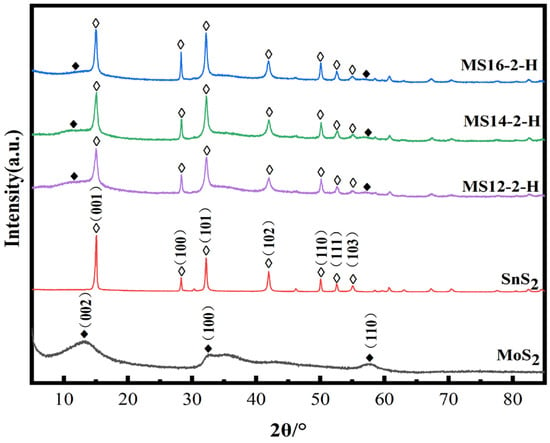
Figure 2.
Powder X-ray diffraction patterns of MoS2/SnS2 composite catalysts with different reaction times.
With increasing reaction time, the characteristic peak of MoS2 gradually broadens and the characteristic peaks of SnS2 gradually narrow, indicating the stronger crystallinity of the SnS2 phase, which on the other hand also means that the structure of SnS2 in the reaction process is more complete.
3.1.2. Morphology Analysis
Scanning electron micrographs of the catalysts MS12-2-H, MS14-2-H and MS16-2-H synthesized at different times are shown in Figure 2. In Figure 3a, the hexagonal SnS2 nanosheets are grown on MoS2 nanosphere flowers [1], whereas the hexagonal SnS2 nanosheets are not uniformly distributed and a large portion of the nanoflake particles are not in contact with the nanosheets.
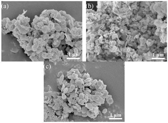
Figure 3.
SEM images of MoS2/SnS2 composite catalysts: (a) MS12-2-H; (b) MS14-2-H; (c) MS16-2-H.
The morphology of the catalysts in Figure 3b changed considerably. The growth of SnS2 nanosheets on the surface of the flower-like morphology of MoS2 was not only more uniformly distributed but also the agglomeration of SnS2 nanosheets was slight, which was obviously different from the other catalysts and could expose more active sites. The SnS2 nanosheets in Figure 3c also have better crystallinity of the grains, although they are more uniformly distributed than in (a), which is consistent with the results for the XRD experiments.
3.1.3. BET Measurements
Table 1 shows the results of the specific surface area test results. The nitrogen adsorption–desorption isotherms were measured at −196 °C after all the samples were pretreated at 105 °C for 12 h prior to measurement. The specific surface area of the composite catalyst showed a trend of increasing and then decreasing with the increase in the reaction time. The reaction time did not have a great influence on the average pore diameter in the range 2.32–2.34 nm and total pore volume of 0.003 cm3/g of the composite catalysts, which were almost negligible. Combined with the analysis of the SEM images of the composite catalysts, the specific surface area of the MoS2 and SnS2 materials was greatly enhanced due to the uniform growth of lamellar SnS2 particles on the surface of the flower-like MoS2 particles; thus, effectively improving the catalytic performance [47].

Table 1.
BET analysis of composite catalysts for different reaction times.
3.1.4. Electrochemical Impedance Measurement
Figure 4 shows the electrochemical impedance plots for the composite catalysts synthesized for different reaction times. In the electrochemical impedance diagram, the radius of the semicircle in the high-frequency region is positively correlated with the charge transfer resistance, reflecting the transfer characteristics of photogenerated electrons and holes in the catalysts under the light conditions. According to the test results, the impedance radius of the MoS2/SnS2 composite catalysts showed a trend of decreasing and then increasing as the reaction time increased, in which the MS14-2-H composite catalyst had the smallest impedance radius and presented a high charge transfer migration efficiency [48]. This also proves that a suitable reaction time has a great impact on the electronic structure of the two components in the catalysts, resulting in the improvement of their charge transfer capacity and thus the photocatalytic degradation performance.
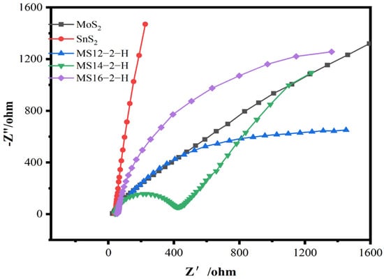
Figure 4.
Electrochemical impedance diagram of MoS2/SnS2 composite catalysts at different reaction times.
3.1.5. Photocatalytic Performance
The degradation of methylene blue solution by MoS2/SnS2 composite catalysts formed at different reaction times is shown in Figure 5. From the figures, it can be observed that the composite catalyst degraded MB in visible light. Of the three catalysts, MS14-2-H exhibited the highest MB degradation rates. With the increasing of the synthesis time of the MoS2/SnS2 composite catalysts, a trend of enhancing and then weakening is observed, which is consistent with the test results of the electrochemical impedance of the composite catalysts. The length of the reaction time has an effect on the electronic structure of the synthesized composite catalyst, thus affecting the migration rate of photogenerated charges in visible light and producing an effect on the performance of the degradation of MB. From the degradation data, it was found that the best catalytic performance was achieved by sample MS14-2-H, which had an 83.0% degradation rate after 80 min of visible light irradiation. This was followed by sample MS12-2-H, which had a 55.9% degradation rate. This corroborates the previous results of the XRD, SEM and EIS analyses.
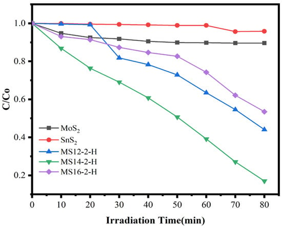
Figure 5.
Degradation rate diagram of MoS2/SnS2 composite catalysts at different reaction times.
3.2. Characterization and Properties of Composite Catalysts in Different Mo–Sn Molar Ratios
3.2.1. XRD Characterization
Figure 6 represents the XRD patterns of the composite catalysts synthesized by varying the molybdenum–tin molar ratio in the reactants at a reaction temperature of 180 °C for 14 h. It can be seen from the figures that the characteristic peaks at 2θ equal to 14.9°, 28.2°, 32.1°, 41.8°, 49.9°, 52.4° and 54.9° correspond to the (001), (100), (101), (102), (110), (111) and (103) crystal planes of SnS2 in the composite catalysts of different molybdenum–tin molar ratios, respectively [45]. In addition, no excess spurious peaks were found in the XRD patterns, indicating that the MoS2/SnS2 composite catalysts were successfully synthesized.
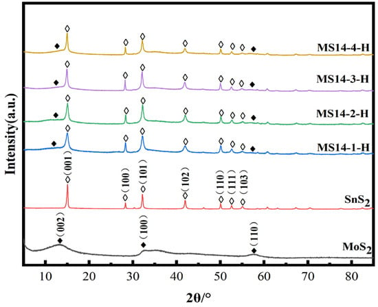
Figure 6.
Powder X-ray diffraction patterns of MoS2/SnS2 composite catalysts synthesized at different molybdenum–tin molar ratios.
When increasing proportion of Mo in the reactants, the characteristic peaks of both MoS2 and SnS2 gradually broadened, especially the (100), (101) and (102) crystal planes in SnS2.
3.2.2. Morphology Analysis
SEM images of the samples MS14-1-H, MS14-2-H, MS14-3-H and MS14-4-H are shown in Figure 7. From the figures, MoS2 particles are shown as having flower-like morphology composed of layered nanosheets. Increasing the proportion of Mo leads to more serious MoS2 agglomeration and the spherical flower particles of MoS2 become more regular. The growth of SnS2 nanosheets on the surface of the flower-like MoS2 morphology exhibits hexagonal morphology and the SnS2 nanosheets have a size of about 400 nm [1]. With an increase in the MoS2 fraction, the main change in the morphology is that the SnS2 nanosheets are not uniformly distributed on the MoS2 surface, as shown in Figure 7c,d. At lower Mo/Sn ratios, the scanning images of the catalyst changed more, and the MoS2 morphology was no longer a regular spherical flower shape but a nano-flake shape. In addition, the SnS2 nanosheets were closely distributed on the MoS2 surface, as shown in Figure 7a,b. The close distribution of the SnS2 nanosheets on the MoS2 surface contributes to the close bonding of the two materials, which can effectively change the electronic structure of the catalyst and increase the photocatalytic active sites.
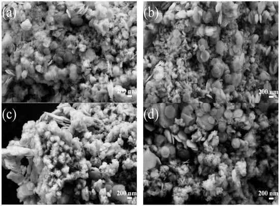
Figure 7.
SEM diagrams of composite catalysts. (a) MS14-1-H. (b) MS14-2-H. (c) MS14-3-H. (d) MS14-4-H.
Figure 8a shows TEM images of the prepared MS14-2-H catalyst, which further shows that the flake SnS2 grows on the surface of MoS2 with a small size. Lattice stripes with distances of 0.68 nm and 0.30 nm are shown in Figure 8b, which could correspond to the (002) plane of MoS2 and the (100) plane of SnS2, respectively [49]. These images objectively further explain the coexistence of SnS2 and MoS2 in the MS14-2-H composite catalyst. In addition to this, the lattice stripe in the (002) plane of MoS2 is larger than the standard spacing value (0.62 nm) according to the Bragg equation:
where d is the lattice spacing, θ is the angle between the incident ray, the reflection line and the reflected crystal plane, λ is the wavelength and n is the number of reflection levels. It is known that under specific conditions, the lattice spacing d is inversely proportional to the angle θ, i.e., at this time, the lattice spacing of the (002) plane of MoS2 is large and the corresponding diffraction peak angle becomes small, which is similar to the diffraction peak of the (002) corresponding to the MoS2 phase of the composite catalyst in the XRD analysis shifting to 10.9°.
2dsinθ = nλ

Figure 8.
TEM images of MS14-2-H: (a) TEM image; (b) high-resolution TEM image.
3.2.3. BET Measurements
Table 2 shows the results of the specific surface area tests of the MoS2/SnS2 composite catalysts with different molybdenum–tin molar ratios. From the data in the table, it can be observed that the specific surface area of the composite catalysts shows a trend of increasing and then decreasing when increasing the molybdenum–tin molar ratio from 1:1 to 4:1. In addition, the average pore diameter of the catalyst was 2.30~2.34 nm and the total pore volume was 0.003 cm3/g.

Table 2.
BET analysis of composite catalysts with different Mo–Sn molar ratios.
The effect of molybdenum–tin molar ratio on the average pore diameter and total pore volume of the composite catalysts is almost negligible, and the effect on the catalyst performance is mainly due to the specific surface area, which is 17.10 m2/g for MS14-2-H, followed by 15.05 m2/g for MS14-1-H. Combined with the analysis of the SEM images of the composite catalysts, the reason for the large differences in the specific surface areas of the catalysts may be due to the size and shape of the particles of MoS2 and SnS2 and the difference in the shape of the particles.
3.2.4. Electrochemical Impedance Measurement
The electrochemical impedance diagrams of the composite catalysts synthesized at different molybdenum–tin molar ratios are shown in Figure 9. According to the test results, the impedance radii of the MoS2/SnS2 composite catalysts showed a trend of decreasing and then increasing as the molybdenum–tin molar ratio increased; the MS14-2-H composite catalyst having the smallest impedance radius. Since the radius of the semicircle in the high-frequency region is positively correlated with the charge transfer resistance in the electrochemical impedance diagram, the sample MS14-2-H has the smallest charge transfer resistance [48].
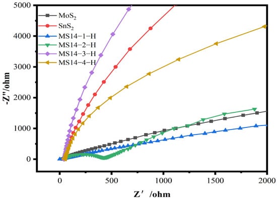
Figure 9.
Electrochemical impedance plot of MoS2/SnS2 composite catalysts synthesized with different molybdenum–tin molar ratios.
3.2.5. Structural Composition Analysis of Materials
Figure 10 shows the XPS diagram of the catalyst MS14-2-H. The elemental composition and elemental chemical valence of the sample catalyst can be identified by analyzing the XPS. From Figure 10a, it can be seen that the catalyst MS14-2-H contains C, O, S, Mo and Sn, and the sample contains all the elements of the target substance by the elemental full spectrum.
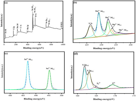
Figure 10.
XPS diagram of catalyst MS14-2-H: (a) survey spectra; (b) Mo 3d; (c) Sn 3d; (d) S 2p.
Figure 10b shows the XPS spectra of Mo 3d, in which five different characteristic peaks appear. It is known from the split peak fitting and literature review [50] that peaks at 229.1 eV and 232.2 eV correspond to Mo4+ 3d5/2 and Mo4+ 3d3/2, respectively, peaks at 233.3 eV and 235.5 eV correspond to Mo6+ 3d5/2 and Mo6+ 3d3/2, respectively, and the peak at 225.8 eV corresponds to S2− 2s. The Mo4+ species belong to MoS2 and Mo6+ signals and may be caused by slight oxidation in air. Only two characteristic peaks appear in Figure 10c, and a review of the literature shows that [51] signals at binding energies of 486.8 eV and 495.3 eV correspond to Sn4+ 3d5/2 and Sn4+ 3d3/2, respectively, whereas the Sn4+ species belong to SnS2. Signals of S2− 2p3/2 and S2− 2p1/2 from the composite catalyst present at binding energies equal to 161.9 eV and 163.1 eV [52]. Therefore, the analysis shows that the composition of the synthesized samples is consistent with the target MoS2/SnS2 catalyst.
3.2.6. Photocatalytic Performance
Figure 11a shows the performance of the composite catalysts synthesized at different molybdenum–tin molar ratios in the degradation of methylene blue solutions. From the degradation data in the figure, the visible light degradation performances in methylene blue solution of the composite catalysts synthesized at different molybdenum–tin molar ratios are better than that of either pure MoS2 or SnS2, indicating that the photocatalytic performance can be effectively improved by using a composite of these two materials. In addition, after visible light irradiation for 80 min, the best catalytic performance was achieved for sample MS14-2-H, which had a degradation rate of 83%, whereas the degradation rate of sample MS14-3-H was 44.6% and that of sample MS14-4-H was 24.7%, indicating that the optimal molybdenum–tin ratio that can effectively improve the photocatalytic performance is 2:1 and that the effect on the photocatalytic performance is limited by only increasing the content of MoS2 in the composite catalyst. Attention should be paid to the reasonable distribution of the two components in the composite catalysts, which is consistent with the previous results of the XRD, SEM and EIS analyses.
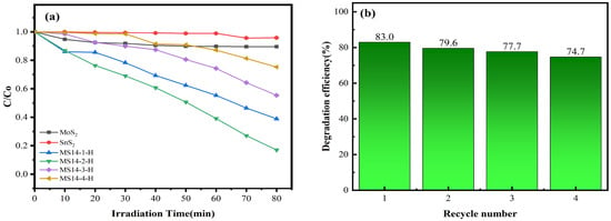
Figure 11.
(a) Degradation rate diagram of MoS2/SnS2 composite catalysts synthesized with different molybdenum–tin molar ratios. (b) Cycling stability testing of the composite catalyst MS14-2-H.
Figure 11b shows the cycling stability test of the composite catalyst MS14-2-H. It can be seen from the figure that the catalytic degradation efficiency of the composite catalyst MS14-2-H in the MB solution decreased from 83.0% to 74.7% after four visible photocatalytic cycle tests and that the loss of photocatalytic activity was 8.3%. This indicates that the stability and repeatability of the composite catalyst MS14-2-H are good, whereas the loss of photocatalytic activity may be caused by the loss of photocatalysis during the cycle test [1].
3.3. Photocatalytic Mechanism
The photocatalytic mechanism of the composite catalyst is shown in Figure 12. MoS2 is a p-type semiconductor material with a narrow band structure (e.g., =1.85 eV), whereas SnS2 is an n-type semiconductor material with a forbidden band width of 2.08 eV [48]. Because the two semiconductors have opposite conductivity types, the electrons and holes of these two semiconductor materials are transferred when they are in close contact to form a heterojunction until the Fermi energy levels of the two semiconductor materials are equal, at which point the p–n heterojunction is in thermal equilibrium and a stable built-in electric field is formed.
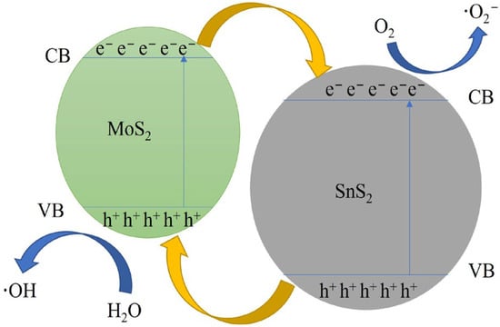
Figure 12.
Possible photocatalytic mechanism for the degradation of methylene blue over a composite catalyst.
In the mechanism diagram of the composite catalyst, the CB and VB of MoS2 are higher than that of SnS2, the energy band structures of both are staggered and the heterogeneous structure of the composite catalyst is of type II. When irradiated by visible light, a large number of photogenerated electrons accumulate in the conduction band and a large number of photogenerated holes accumulate in the valence band of both semiconductor materials. Under the effect of potential difference, electrons in the conduction band of MoS2 are transferred to the conduction band of SnS2, whereas holes in the valence band of SnS2 are transferred to the valence band of MoS2. In this way, the electrons and holes can be separated to the maximum extent.
The photocatalytic degradation of MB by composite catalysts under visible light is mainly based on the chemical reaction of the photogenerated electron reduction transferred to the surface of the photocatalyst with dissolved oxygen, which produces strongly oxidizing superoxide radicals (·O2−), and the chemical reaction of the strongly oxidizing holes transferred to the surface of the photocatalyst with hydroxyl radicals (OH−) in water and aqueous solutions, which produces hydroxyl radicals (·OH) [1]. The photocatalytic reaction process is as follows:
MoS2/SnS2 + hν → e− + h+
e− + O2 → ·O2−
h+ + H2O/OH− → ·OH
·O2− + MB → CO2 + H2O
·OH + MB → CO2 + H2O
4. Conclusions
In summary, a novel MoS2/SnS2 heterostructure was successfully prepared by growing SnS2 nanosheets on MoS2 nanospheres by a facile multi-step hydrothermal method. Based on the measurements of the XRD, SEM, HRTEM and XPS analyses, the present composite sample was found to have high crystalline quality and excellent heterojunction formation. By constructing heterojunctions between the two sulfides, an improved photocatalytic performance was achieved, which greatly solved the problems of low visible light utilization and photogenerated charge recombination. Compared with pure MoS2 or SnS2, this easily accessible and simple composition photocatalyst shows higher photocatalytic activity and good photostability; these effects are attributed to the constructed heterostructure, better light trapping and rapid separation and migration of light-induced electron and hole pairs with the assistance of the MoS2 metal phase. The optimal MoS2/SnS2 photocatalyst (i.e., the one that achieved the best photocatalytic performance) had a degradation efficiency of 83.0% for MB solution, which was 8.3 times higher than the degradation with pure MoS2 and 16.6 times higher than the degradation with pure SnS2. The experimental results indicate that this construction of heterojunctions between semiconductors can effectively improve the photocatalytic ability of MoS2/SnS2 catalysts in terms of MB degradation.
Author Contributions
Conceptualization, Y.T.; software, Y.L. (Yunfei Liu) and Y.L. (Yinong Lu); data curation, G.M.; writing—original draft preparation, G.M.; writing—review and editing, Y.T. and Z.P. All authors have read and agreed to the published version of the manuscript.
Funding
This work was supported by the priority academic program development of Jiangsu Higher Education Institution (PAPD).
Institutional Review Board Statement
Not applicable.
Informed Consent Statement
Not applicable.
Data Availability Statement
The data presented in this study are available on request from the corresponding author.
Acknowledgments
The authors gratefully acknowledge the assistance from Yaqiu Tao and Zhigang Pan from NJTECH and the staff from State Key Laboratory of Materials-Oriented Chemical Engineering.
Conflicts of Interest
The authors declare no conflict of interest.
References
- Chen, C.; Shen, M.; Li, Y. One pot synthesis of 1T@2H-MoS2/SnS2 heterojunction as a photocatalyst with excellent visible light response due to multiphase synergistic effect. Chem. Phys. 2021, 548, 11230. [Google Scholar] [CrossRef]
- Fang, Y.Y.; Huang, Q.Z.; Liu, P.Y.; Shi, J.F.; Xu, G. A facile dip-coating method for the preparation of separable MoS2 sponges and their high-efficient adsorption behaviors of Rhodamine B. Inorg. Chem. Front. 2018, 5, 827–834. [Google Scholar] [CrossRef]
- Omar, A.M.; Metwalli, O.I.; Saber, M.R.; Khabiri, G.; Ali, M.E.M.; Hassen, A.; Khalil, M.M.H.; Maarouf, A.A.; Khalil, A.S.G. Revealing the role of the 1T phase on the adsorption of organic dyes on MoS2 nanosheets. RSC Adv. 2019, 9, 28345–28356. [Google Scholar] [CrossRef] [PubMed]
- Ghadiri, M.; Mohammadi, M.; Asadollahzadeh, M.; Shirazian, S. Molecular separation in liquid phase: Development of mechanistic model in membrane separation of organic compounds. J. Mol. Liq. 2018, 262, 336–344. [Google Scholar] [CrossRef]
- Dong, L.; Li, M.; Zhang, S.; Si, X.; Bai, Y.; Zhang, C. NH2-Fe3O4-regulated graphene oxide membranes with well-defined laminar nanochannels for desalination of dye solutions. Desalination 2020, 476, 114227. [Google Scholar] [CrossRef]
- Maniyam, M.N.; Ibrahim, A.L.; Cass, A.E.G. Decolourization and biodegradation of azo dye methyl red by Rhodococcus strain UCC 0016. Environ. Technol. 2020, 41, 71–85. [Google Scholar] [CrossRef]
- Türgay, O.; Ersöz, G.; Atalay, S.; Forss, J.; Welander, U. The treatment of azo dyes found in textile industry wastewater by anaerobic biological method and chemical oxidation. Sep. Purif. Technol. 2011, 79, 26–33. [Google Scholar] [CrossRef]
- Xie, W.H.; Shi, Y.L.; Wang, Y.X.; Zheng, Y.L.; Liu, H.; Hu, Q.; Wei, S.Y.; Gu, H.B.; Guo, Z.H. Electrospun iron/cobalt alloy nanoparticles on carbon nano fibers towards exhaustive electrocatalytic degradation of tetracycline in wastewater. Chem. Eng. J. 2021, 405, 126585. [Google Scholar] [CrossRef]
- Yin, M.; Li, Z.; Kou, J.; Zou, Z. Mechanism Investigation of Visible Light-Induced Degradation in a Heterogeneous TiO2/Eosin Y/Rhodamine B System. Environ. Sci. Technol. 2009, 43, 8361–8366. [Google Scholar] [CrossRef]
- Saber, M.R.; Khabiri, G.; Maarouf, A.A.; Ulbricht, M.; Khalil, A.S.G. A comparative study on the photocatalytic degradation of organic dyes using hybridized 1T/2H, 1T/3R and 2H MoS2 nano-sheets. RSC Adv. 2018, 8, 26364–26370. [Google Scholar] [CrossRef]
- Hu, X.; Cheng, L.; Li, G. One-pot hydrothermal fabrication of basic bismuth nitrate/BiOBr composite with enhanced photocatalytic activity. Mater. Lett. 2017, 203, 77–80. [Google Scholar] [CrossRef]
- Cheng, L.; Hu, X.; Hao, L. Ultrasonic-assisted in-situ fabrication of BiOBr modified Bi2O2CO3 microstructure with enhanced photocatalytic performance. Ultrason. Sonochem. 2018, 44, 137–145. [Google Scholar] [CrossRef]
- Lu, D.; Wang, H.; Zhao, X.; Kondamareddy, K.K.; Ding, J.; Li, C.; Fang, P. Highly Efficient Visible-Light-Induced Photoactivity of Z-Scheme g-C3N4/Ag/MoS2 Ternary Photocatalysts for Organic Pollutant Degradation and Production of Hydrogen. ACS Sustain. Chem. Eng. 2017, 5, 1436–1445. [Google Scholar] [CrossRef]
- Cho, S.-Y.; Kim, S.J.; Lee, Y.; Kim, J.-S.; Jung, W.-B.; Yoo, H.-W.; Kim, J.; Jung, H.-T. Highly Enhanced Gas Adsorption Properties in Vertically Aligned MoS2 Layers. ACS Nano 2015, 9, 9314–9321. [Google Scholar] [CrossRef]
- Massey, A.T.; Gusain, R.; Kumari, S.; Khatri, O.P. Hierarchical Microspheres of MoS2 Nanosheets: Efficient and Regenerative Adsorbent for Removal of Water-Soluble Dyes. Ind. Eng. Chem. Res. 2016, 55, 7124–7131. [Google Scholar] [CrossRef]
- Wang, Q.H.; Kalantar-Zadeh, K.; Kis, A.; Coleman, J.N.; Strano, M.S. Electronics and optoelectronics of two-dimensional transition metal dichalcogenides. Nat. Nanotechnol. 2012, 7, 699–712. [Google Scholar] [CrossRef]
- Khabiri, G.; Aboraia, A.M.; Omar, S.; Soliman, M.; Omar, A.M.A.; Kirichkov, M.V.; Soldatov, A.V. The enhanced photocatalytic performance of SnS2@MoS2 QDs with highly-efficient charge transfer and visible light utilization for selective reduction of mythlen-blue. Nanotechnology 2020, 31, 475602. [Google Scholar] [CrossRef]
- Chang, K.; Hai, X.; Pang, H.; Zhang, H.B.; Shi, L.; Liu, G.G.; Liu, H.M.; Zhao, G.X.; Li, M.; Ye, J.H. Targeted Synthesis of 2H-and 1T-Phase MoS2 Monolayers for Catalytic Hydrogen Evolution. Adv. Mater. 2016, 28, 10033–10041. [Google Scholar] [CrossRef]
- Xiao, X.; Wang, Y.; Xu, X.; Yang, T.; Zhang, D. Preparation of the flower-like MoS2/SnS2 heterojunction as an efficient electrocatalyst for hydrogen evolution reaction. Mol. Catal. 2020, 487, 110890. [Google Scholar] [CrossRef]
- Xu, H.; Liu, S.; Ding, Z.; Tan, S.J.R.; Yam, K.M.; Bao, Y.; Nai, C.T.; Ng, M.-F.; Lu, J.; Zhang, C.; et al. Oscillating edge states in one-dimensional MoS2 nanowires. Nat. Commun. 2016, 7, 12904. [Google Scholar] [CrossRef]
- Liang, Z.; Sun, B.; Xu, X.; Cui, H.; Tian, J. Metallic 1T-phase MoS2 quantum dots/g-C3N4 heterojunctions for enhanced photocatalytic hydrogen evolution. Nanoscale 2019, 11, 12266–12274. [Google Scholar] [CrossRef] [PubMed]
- Liu, Q.; Fang, Q.; Chu, W.; Wan, Y.; Li, X.; Xu, W.; Habib, M.; Tao, S.; Zhou, Y.; Liu, D.; et al. Electron-Doped 1T-MoS2 via Interface Engineering for Enhanced Electrocatalytic Hydrogen Evolution. Chem. Mater. 2017, 29, 4738–4744. [Google Scholar] [CrossRef]
- Voiry, D.; Salehi, M.; Silva, R.; Fujita, T.; Chen, M.; Asefa, T.; Shenoy, V.B.; Eda, G.; Chhowalla, M. Conducting MoS2 Nanosheets as Catalysts for Hydrogen Evolution Reaction. Nano Lett. 2013, 13, 6222–6227. [Google Scholar] [CrossRef] [PubMed]
- Wang, H.; Lu, Z.; Kong, D.; Sun, J.; Hymel, T.M.; Cui, Y. Electrochemical Tuning of MoS2 Nanoparticles on Three-Dimensional Substrate for Efficient Hydrogen Evolution. ACS Nano 2014, 8, 4940–4947. [Google Scholar] [CrossRef]
- Acerce, M.; Voiry, D.; Chhowalla, M. Metallic 1T phase MoS2 nanosheets as supercapacitor electrode materials. Nat. Nanotechnol. 2015, 10, 313–318. [Google Scholar] [CrossRef] [PubMed]
- Li, H.; Chen, S.; Jia, X.; Xu, B.; Lin, H.; Yang, H.; Song, L.; Wang, X. Amorphous nickel-cobalt complexes hybridized with 1T-phase molybdenum disulfide via hydrazine-induced phase transformation for water splitting. Nat. Commun. 2017, 8, 15377. [Google Scholar] [CrossRef]
- Liu, Y.; Li, Y.; Peng, F.; Lin, Y.; Yang, S.; Zhang, S.; Wang, H.; Cao, Y.; Yu, H. 2H- and 1T- mixed phase few-layer MoS2 as a superior to Pt co-catalyst coated on TiO2 nanorod arrays for photocatalytic hydrogen evolution. Appl. Catal. B Environ. 2019, 241, 236–245. [Google Scholar] [CrossRef]
- Li, J.; Liu, E.Z.; Ma, Y.N.; Hu, X.Y.; Wan, J.; Sun, L.; Fan, J. Synthesis of MoS2/g-C3N4 nanosheets as 2D heterojunction photocatalysts with enhanced visible light activity. Appl. Surf. Sci. 2016, 364, 694–702. [Google Scholar] [CrossRef]
- Chen, Y.K.; Tan, L.J.; Sun, M.L.; Lu, C.H.; Kou, J.H.; Xu, Z.Z. Enhancement of photocatalytic performance of TaON by combining it with noble-metal-free MoS2 cocatalysts. J. Mater. Sci. 2019, 54, 5321–5330. [Google Scholar] [CrossRef]
- Yin, S.; Ding, Y.; Luo, C.; Hu, Q.S.; Chen, Y.; Di, J.; Wang, B.; Xia, J.X.; Li, H.M. Construction of 2D/2D MoS2/PbBiO2Cl nanosheet photocatalysts with accelerated interfacial charge transfer for boosting visible light photocatalytic activity. Colloid. Surface A 2021, 609, 125655. [Google Scholar] [CrossRef]
- Mondal, C.; Ganguly, M.; Pal, J.; Roy, A.; Jana, J.; Pal, T. Morphology Controlled Synthesis of SnS2 Nanomaterial for Promoting Photocatalytic Reduction of Aqueous Cr(VI) under Visible Light. Langmuir 2014, 30, 4157–4164. [Google Scholar] [CrossRef]
- Tu, J.-R.; Shi, X.-F.; Lu, H.-W.; Yang, N.-X.; Yuan, Y.-J. Facile fabrication of SnS2 quantum dots for photoreduction of aqueous Cr(VI). Mater. Lett. 2016, 185, 303–306. [Google Scholar] [CrossRef]
- Sun, Y.; Li, G.; Xu, J.; Sun, Z. Visible-light photocatalytic reduction of carbon dioxide over SnS2. Mater. Lett. 2016, 174, 238–241. [Google Scholar] [CrossRef]
- Li, X.; Zhu, J.; Li, H. Comparative study on the mechanism in photocatalytic degradation of different-type organic dyes on SnS2 and CdS. Appl. Catal. B Environ. 2012, 123–124, 174–181. [Google Scholar] [CrossRef]
- Lucena, R.; Fresno, F.; Conesa, J.C. Hydrothermally synthesized nanocrystalline tin disulphide as visible light-active photocatalyst: Spectral response and stability. Appl. Catal. A Gen. 2012, 415–416, 111–117. [Google Scholar] [CrossRef]
- Liu, H.; Su, Y.; Chen, P.; Wang, Y. Microwave-assisted solvothermal synthesis of 3D carnation-like SnS2 nanostructures with high visible light photocatalytic activity. J. Mol. Catal. A Chem. 2013, 378, 285–292. [Google Scholar] [CrossRef]
- Zhang, Y.; Zhang, F.; Yang, Z.; Xue, H.; Dionysiou, D.D. Development of a new efficient visible-light-driven photocatalyst from SnS2 and polyvinyl chloride. J. Catal. 2016, 344, 692–700. [Google Scholar] [CrossRef]
- Christoforidis, K.C.; Sengele, A.; Keller, V.; Keller, N. Single-Step Synthesis of SnS2 Nanosheet-Decorated TiO2 Anatase Nanofibers as Efficient Photocatalysts for the Degradation of Gas-Phase Diethylsulfide. ACS Appl. Mater. Inter. 2015, 7, 19324–19334. [Google Scholar] [CrossRef]
- Zhang, X.-Y. Developing bioenergy to tackle climate change: Bioenergy path and practice of Tianguan group. Adv. Clim. Chang. Res. 2016, 7, 17–25. [Google Scholar] [CrossRef]
- Gao, X.; Huang, G.; Gao, H.; Pan, C.; Wang, H.; Yan, J.; Liu, Y.; Qiu, H.; Ma, N.; Gao, J. Facile fabrication of Bi2S3/SnS2 heterojunction photocatalysts with efficient photocatalytic activity under visible light. J. Alloys Compd. 2016, 674, 98–108. [Google Scholar] [CrossRef]
- Zhang, Z.Y.; Huang, J.D.; Zhang, M.Y.; Yuan, L.; Dong, B. Ultrathin hexagonal SnS2 nanosheets coupled with g-C3N4 nanosheets as 2D/2D heterojunction photocatalysts toward high photocatalytic activity. Appl. Catal. B-Environ. 2015, 163, 298–305. [Google Scholar] [CrossRef]
- Liang, Z.Q.; Guo, Y.C.; Xue, Y.J.; Cui, H.Z.; Tian, J. 1T-phase MoS2 quantum dots as a superior co-catalyst to Pt decorated on carbon nitride nanorods for photocatalytic hydrogen evolution from water. Mater. Chem. Front. 2019, 3, 2032–2040. [Google Scholar] [CrossRef]
- Chen, C.Z.; Zang, J.Y.; Wang, Q.; Li, Y.Z. Loading SnS2 nanosheets decorated with MoS2 nanoparticles on a flake-shaped g-C3N4 network for enhanced photocatalytic performance. Crystengcomm 2021, 23, 4680–4693. [Google Scholar] [CrossRef]
- Holler, F.J.; Skoog, D.A.; Crouch, S.R. Principles of Instrumental Analysis; Cengage Learning: Boston, MA, USA, 2007. [Google Scholar]
- Zhang, Y.C.; Li, J.; Zhang, M.; Dionysiou, D.D. Size-Tunable Hydrothermal Synthesis of SnS2 Nanocrystals with High Performance in Visible Light-Driven Photocatalytic Reduction of Aqueous Cr (VI). Environ. Sci. Technol. 2011, 45, 9324–9331. [Google Scholar] [CrossRef]
- Qiang, T.T.; Chen, L.; Xia, Y.J.; Qin, X.T. Dual modified MoS2/SnS2 photocatalyst with Z-scheme heterojunction and vacancies defects to achieve a superior performance in Cr (VI) reduction and dyes degradation. J. Clean. Prod. 2021, 291, 125213. [Google Scholar] [CrossRef]
- Cui, B.W.; Wang, Y.H.; Zhang, F.; Xiao, X.; Su, Z.Q.; Dai, X.C.; Zhang, H.; Huang, S. Hydrothermal synthesis of SnS2/MoS2 Nanospheres for enhanced adsorption capacity of organic dyes. Mater. Res. Express 2020, 7, 015016. [Google Scholar] [CrossRef]
- Mangiri, R.; Kumar, K.S.; Subramanyam, K.; Ratnakaram, Y.C.; Sudharani, A.; Reddy, D.A.; Vijayalakshmi, R.P. Boosting solar driven hydrogen evolution rate of CdS nanorods adorned with MoS2 and SnS2 nanostructures. Colloid. Interface Sci. Commun. 2021, 43, 100437. [Google Scholar] [CrossRef]
- Yin, S.K.; Li, J.Z.; Sun, L.L.; Li, X.; Shen, D.; Song, X.H.; Huo, P.W.; Wang, H.Q.; Yang, Y.S. Construction of Heterogenous S-C-S MoS2/SnS2/r-GO Heterojunction for Efficient CO2 Photoreduction. Inorg. Chem. 2019, 58, 15590–15601. [Google Scholar] [CrossRef]
- Teng, Y.Q.; Zhao, H.L.; Zhang, Z.J.; Li, Z.L.; Xia, Q.; Zhang, Y.; Zhao, L.N.; Du, X.F.; Du, Z.H.; Lv, P.P.; et al. MoS2 Nanosheets Vertically Grown on Graphene Sheets for Lithium-Ion Battery Anodes. ACS Nano 2016, 10, 8526–8535. [Google Scholar] [CrossRef]
- Man, X.L.; Liang, P.; Shu, H.B.; Zhang, L.; Wang, D.; Chao, D.L.; Liu, Z.G.; Du, X.Q.; Wan, H.Z.; Wang, H. Interface Synergistic Effect from Layered Metal Sulfides of MoS2/SnS2 van der Waals Heterojunction with Enhanced Li-Ion Storage Performance. J. Phys. Chem. C 2018, 122, 24600–24608. [Google Scholar] [CrossRef]
- Tang, T.Y.; Zhang, T.; Zhao, L.N.; Zhang, B.; Li, W.; Xu, J.J.; Zhang, L.; Qiu, H.L.; Hou, Y.L. Multifunctional ultrasmall-MoS2/graphene composites for high sulfur loading Li-S batteries. Mater. Chem. Front. 2020, 4, 1483–1491. [Google Scholar] [CrossRef]
Disclaimer/Publisher’s Note: The statements, opinions and data contained in all publications are solely those of the individual author(s) and contributor(s) and not of MDPI and/or the editor(s). MDPI and/or the editor(s) disclaim responsibility for any injury to people or property resulting from any ideas, methods, instructions or products referred to in the content. |
© 2023 by the authors. Licensee MDPI, Basel, Switzerland. This article is an open access article distributed under the terms and conditions of the Creative Commons Attribution (CC BY) license (https://creativecommons.org/licenses/by/4.0/).