1. Introduction
With the rapid development of the construction industry, natural aggregates were, and continue to be, consumed in large quantities. At the same time, the construction process produced a great deal of construction waste, thus leading to severe environmental pollution [
1,
2,
3]. The crushing, cleaning, and processing of construction waste in order to produce recycled aggregate concrete (RAC) can contribute toward significant benefits [
4,
5,
6]. However, compared with ordinary concrete, recycled aggregate concrete possesses certain flaws, such as low strength and a significant degree of water absorption [
7,
8,
9]. With respect to this, steel tubes inhibit the generation and development of vertical cracks in concrete, thus the restraining quality of steel tubes can also improve the compressive strength and deformation ability of concrete [
10,
11,
12,
13]. The local buckling of the steel tube may be successfully avoided by the support effect of RAC deformation on the interior of the steel tube during the application of stress. Therefore, the recycled aggregate concrete-filled steel tube (RACFST) can utilize the benefits of steel tubes and RAC for the purposes of increasing force characteristics, as well as with respect to addressing the issue of construction waste. In so doing this, a wide range of application possibilities in the growth of the green building industry is opened up.
In order to promote the application of the RACFST in the context of practical engineering, it is necessary to reveal the earthquake failure mechanism of RACFST members and frames. Certain scholars demonstrated the difference in seismic behavior failure mechanisms between the RACFST columns and with ordinary concrete-filled steel tube columns. Moreover, Tang et al. [
14,
15] conducted the cyclic loading test on the RAC and on ordinary concrete-filled steel tube columns, then studied their respective seismic behaviors. The RACFST column exhibited a superior bearing capacity and ductility, as well as, at the same displacement level, a slightly lower energy dissipation coefficient. The research shows that the RACFST column possesses excellent seismic performance and provides a reference for the theoretical research of the RACFST. However, the research was only carried out with respect to the concrete-filled steel tube column, which incorporated 100% recycled concrete aggregates and ordinary concrete-filled steel tubes. This approach, however, neglected to account for the fact that the shape of the steel tube and the replacement ratio of the recycled aggregate can also affect the performance of the RACFST column. Therefore, certain scholars took a closer look in regard to this. Yang et al. [
16] studied the effect regarding the shape of the steel tube, as well as with respect to the replacement ratio of the recycled concrete on the seismic behavior of the RACFST. The failure mode of the RACFST column is similar to that of an ordinary concrete-filled steel tube column. The ultimate bearing capacity of the circular RACFST column, with a 25% replacement rate, is lower than that of the square RACFST column, whereby it is composed of a 50% recycled coarse aggregate, which is higher than that of the square RACFST column. Xu et al. [
17] studied the seismic behavior of the square RACFST columns by changing the replacement ratio of the RAC and then established a new calculation method for the bearing capacity of the RACFST. The results show that changing the replacement ratio of the recycled aggregate has little effect on the hysteretic properties of the RACFST column. Moreover, the displacement ductility can still meet the seismic requirements. Due to the above studies being different in terms of the source and particle size of the recycled aggregate, loading device, and the selection of design parameters, there may be some minor errors in the test results. However, the conclusion is the same: the seismic behavior of the RACFST column undergoes little change with respect to the increase in the replacement ratio of the recycled aggregate. Indeed, the hysteretic performance of the RACFST column is similar, or slightly altered, with respect to that of ordinary concrete-filled steel tube columns; in addition, the seismic performance remains good. With respect to this, engineering bearing structures can use RACFST columns based on their seismic performance index. In order to study the seismic behavior of recycled aggregate concrete frame joints, Zhou et al. [
18] discussed the influence of length and volume content of the fiber that are regarded as the parameters of RAC joints. In addition, Su et al. [
19] took the replacement ratio of recycled aggregate as the change parameter in order to carry out a cyclic loading test on the recycled concrete frame joints. Subsequently, Xiao et al. [
20] adopted a recycled coarse aggregate as the structural material in a novel beam–column joint with design for deconstruction connections. The above studies demonstrate that the RAC is feasible in the practical application of frame joints, but this does not extend to the finite element model in regard to successfully analyzing the performance of recycled concrete frame joints under different parameters. The RACFST, therefore, is generally utilized as columns or arch ribs for the purposes of axial load-bearing structures. The other components and overall structural form affect the force characteristics of the columns and the arch ribs in the structure. Therefore, their mechanical properties and working mechanisms differ from the individual components. As such, the overall structural performance requires more intensive study, especially in regard to the seismic behavior of the overall frame structures.
Combined with the current body of research regarding steel tube recycled concrete columns and recycled aggregate concrete frame joints, Wen et al. [
21] discussed the experimental research on the seismic behavior of steel tube, bulk mass, recycled, and concrete column–steel beam frameworks. They simulated the finite element simulation based on the test, but the number of variable parameters and the analysis depth of the finite element simulation required increasing. In addition, more details regarding the numerical modeling did not provide much with respect to readership and remodeling. Moreover, they used large-size recycled concrete blocks, which have a positive impact on the popularization and utilization of discarded concrete. However, the existence of blocks reduces the bearing capacity and hysteretic properties of specimens when compared with all cast-in-place columns. Regarding cast-in-place concrete, Chen et al. [
22] researched the seismic behavior of the RACFST circular frames. The frames demonstrated optimal deformation performance, collapse resistance, and energy dissipation capacity. In addition, the frame possessed exemplary seismic behavior, which could be applied in high-rise buildings in order to mitigate the dangers that occur in high-intensity seismic areas. However, both studies only discussed the seismic behavior of the RACFST circular frames. Our group [
23], instead, conducted small-scale model tests on recycled concrete frames with square steel tubes. The ductility of the S-RACFST was found to be higher than that of the circular specimen reported by Chen et al. [
22]. However, this study mainly focuses on the test, whereas there are few other studies that investigated the variation parameters.
To summarize, combining the advantages of renewable resources and concrete-filled steel tubes can solve environmental problems and can also still possess good seismic performance. Having said this, a study on the seismic behavior of the RACFST frame still needs to be perfected. However, relying entirely on a test for this aspect is too expensive, and it is difficult to establish a complete research system utilizing it alone. As such, it is essential to establish an accurate finite element model for the purposes of parametric analysis. In this study, as based on the group’s previous studies [
23], the seismic behavior of the RACFST frame was numerically analyzed. Indeed, the finite element model of the S-RACFST frame was established by ABAQUS software, and the design parameters of the specimen were changed in order to obtain the seismic behavior indicators, such as the hysteretic curve, ductility coefficient, energy dissipation coefficient, and stiffness degradation. The sensitivity of each parameter to the seismic behavior of the specimen was evaluated via grey correlation analysis, which provides a reference for the engineering design and theoretical analyses.
2. Establishment of the Finite Element Model for the Seismic Behavior of the S-RACFST Frame Specimens
2.1. Design of Specimens
The S-RACFST frame seismic test model that was constructed and completed in the group’s previous study [
23] was selected for the current work. The frame structure geometry of the model is shown in
Figure 1. The applied coarse aggregates were RCAs obtained from the waste concrete specimens in the Key Laboratory of Disaster Prevention and Structural Safety of China, Ministry of Education. The physical properties of the RACs are provided in
Table 1. The strength grade of the RAC in regard to the steel tube and beam was C40; the replacement ratio of the recycled coarse aggregate was 100%; the physical properties of the recycled aggregate and the steel tube grade was Q235; and the test axial compression ratio was taken as 0.8. The frame-specific design parameters, reinforcement, and material properties were reported, in detail, in a previous study by the group [
23].
2.2. Loading System
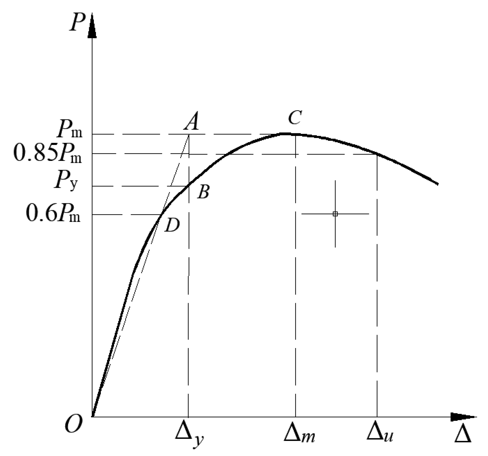
In the actual project, the situation of the frame was simulated in this study. The same vertical loading was applied simultaneously to the top of the two columns. Then, a low-frequency cyclic lateral load was applied transversely and horizontally when the vertical loading stabilized. The 1500 kN hydraulic jack was used to apply the vertical loading at the top of the column; further, this loading was maintained throughout the loading operation. In the process of horizontal loading, joint control of force and displacement was used. In addition, when conducting the horizontal loading, a graduated approach with 5 kN loading levels was used, with each loading level cycled once before the specimen yields. The displacement loading was carried out in multiples of the yield displacement Δy after the specimen yields were performed, thereby corresponding to three cycles per loading step. The loading was stopped when the loading dropped to 85% of the peak loading. Lastly, the model was cycled once under each loading level during the validation and extended analysis stage in order to save time and cost.
2.3. Material Constitutive Model
The constitutive behavior of the steel-adopted elastic–plastic hardening model was determined, including with respect to the elastic and intensive sections. This constitutive behavior not only accurately simulates the properties of steel but also facilitates the convergence of the finite element model. After the yield stress is reached in the elastic phase , the plastic modulus of the steel is taken as in the intensive section. In addition, where is the stress, Es is the elastic modulus of steel, and ε is the strain.
The RAC was analyzed within a plastic damage model; moreover, the corresponding key parameters for this are shown in
Table 2. The concrete damage factors, in regard to tension and compression, are calculated as in Equation (1), according to the energy equivalence principle [
24].
where
d is the concrete damage factor;
σ is the real concrete stress;
ε is the concrete strain; and
E0 is the initial concrete modulus of elasticity.
The compressed constitutive relationship of the interior RAC in the S-RACFST was detailed in the previous research results of the authors [
25]. However, the compressed constitutive relationship of the RAC in the beam was adopted from Xiao [
26]. The constitutive relationship considers the effect of the replacement ratio of the RAC, which was based on the ordinary concrete in the “Code for design of concrete structures” (China GB50010-2010). The constitutive relationship expressions are shown in Equations (2)–(6).
where
is the RAC peak strain, R is the replacement ratio of RA, and fc is the measured RAC compressive strength.
As the tensile performance of the interior RAC is not significantly affected by the restraint of the external steel tube, the uniaxial tensile stress–strain relationship of the interior RAC is taken according to the “Code for design of concrete structures” (China GB50010-2010) as shown in Equations (7) and (8).
where
is the peak tensile stress, , is the peak tensile strain, and .
2.4. Modeling Method
The interaction between the square steel tube and the interior RAC adopted “surface-to-surface contact”. Further, a small bond slip could occur between the square steel tube and the RAC. The normal direction model adopted the “hard” contact, and the tangent direction model adopted the “penalty” contact. In addition, the friction coefficient was taken as 0.25 [
27]. The reinforcement skeleton was embedded in the RAC beam by “embed”, whereby the effect of the bonding slip was neglected. The steel tube and RAC were all made of the same 8-node hexahedral linear reduced integral unit (C3D8R), and the three-dimensional two-node truss unit (T3D2) was used for the reinforcing bars and stirrups in the beam.
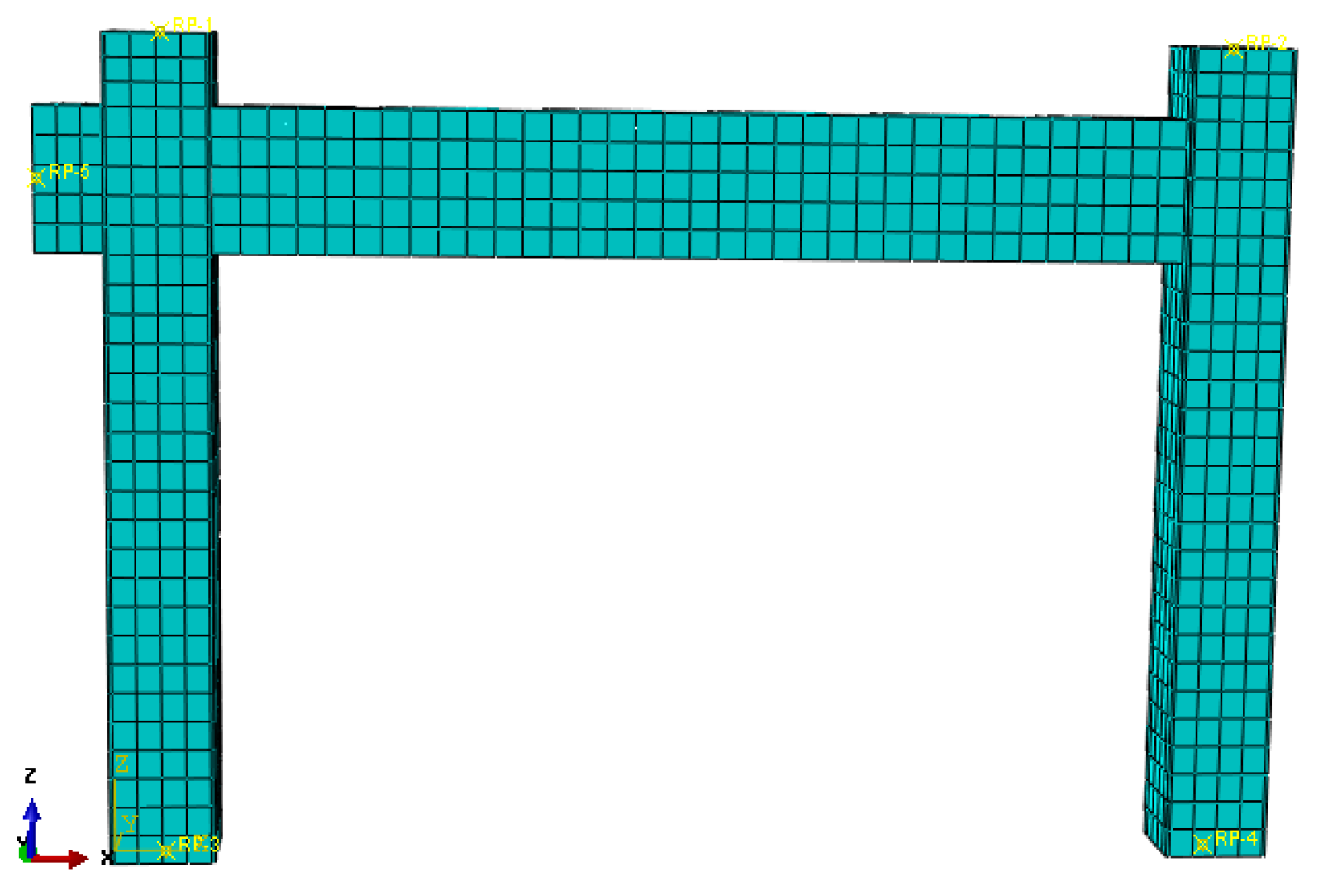
The mesh division density is very crucial for the finite element model analysis calculation. First, with respect to the initial analysis, a reasonable mesh division was taken. Then, the mesh density division was doubly expanded and then analyzed again. Next, the two results were compared until the two differences were found to be less than 1%. Then, the size of 40 mm was finally chosen. The mesh division in regard to the finite element model of the S-RACFST frame specimen is shown in
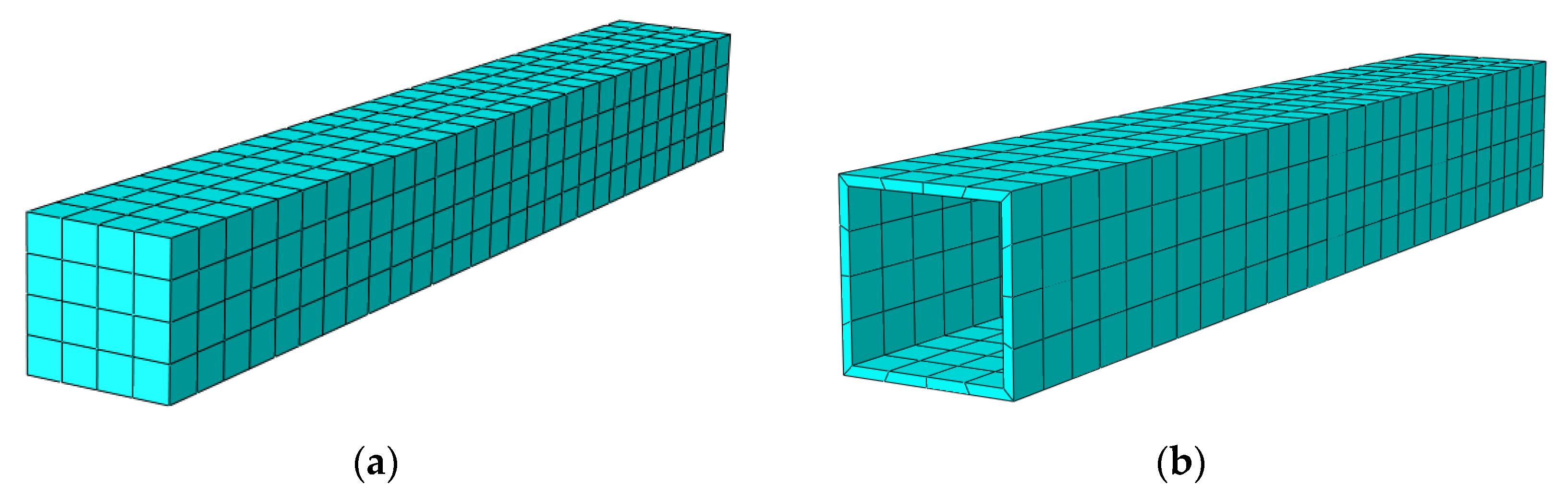
Figure 2. Further, the mesh division of the interior RAC and the square steel tube components are shown in
Figure 3.
The boundary condition of the finite element model was consistent with the test that was established according to the test conditions. The bottom of the finite element model steel tube was completely fixed—i.e., Ux = Uy = Uz = URx = URy = URz = 0—whereby the vertical pressure was applied to the top of the steel tube along the Z-axis, and a low-frequency cyclic lateral displacement loading was applied along the horizontal X-axis. Then, two analysis steps in Abaqus were constructed in order to apply the loading. The boundary conditions and vertical loading were applied in the first analysis step. In the second analysis step, the horizontal loading was controlled by the displacement that was applied to the joints. The same displacement amplitude as the actual test was entered in the “Amplitude” command. Furthermore, the S-RACFST frame specimen displacement control was applied through a reference point that was coupled to a horizontal loading mat plate.
Due to the incremental–interactive method possessing the advantages of the incremental and iterative methods, the incremental–interactive method was selected for the calculation in this study. In addition, the automatic incremental method was used for the incremental method. Regarding the iterative method, Newton’s method is computationally large and the convergence is good; thus, Newton’s method was chosen in this study.
2.5. Finite Element Model Validation
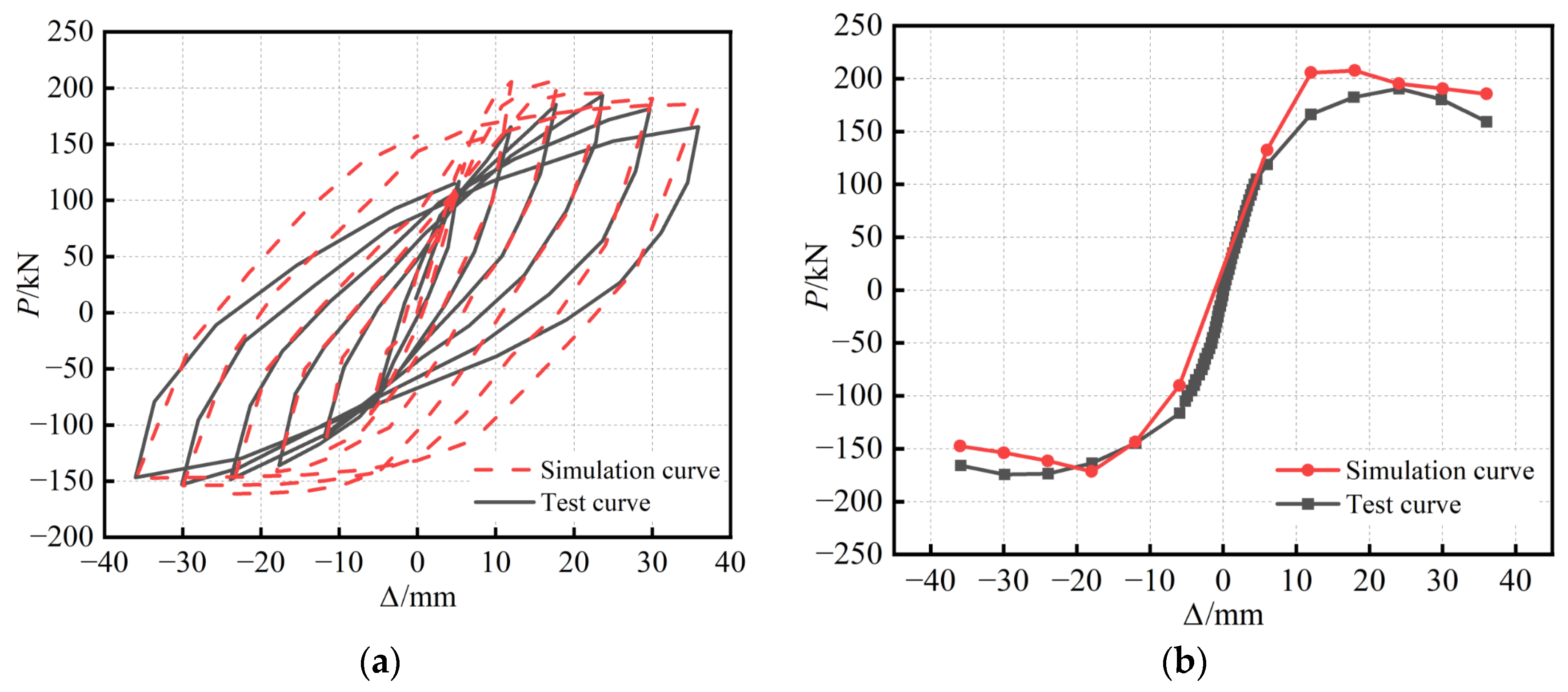
Figure 4a shows the results of the finite element hysteretic simulation curve for the S-RACFST frame specimen when compared with the test. The hysteretic test curve is derived from the previous research results of our group [
23]. In addition, it is shown that the hysteretic curve obtained from the simulation generally agrees well with the test. The simulation curves of the elastic phase during the positive and negative loading process agree with the test curves. Furthermore, the hysteretic simulation curve in the elastic–plastic stage exhibits a higher loading stiffness than the hysteretic test curve. Moreover, the hysteretic loop area obtained from the finite element is slightly larger than the test. The difference between the hysteretic loop areas is relatively more pronounced in the later loading period. The reason for this is that the geometric defects, concrete cracks, and damage during the test are not fully considered in the simulation analysis. Therefore, the bearing capacity and hysteresis loop area obtained from the simulation are higher than those found in the test. Overall, the model can simulate the whole process of specimen development under reciprocal loading.
Figure 4b shows the results of the finite element simulative backbone curve for the S-RACFST frame specimen when compared with the experiment. The stiffness of the finite element model is slightly more significant than the test in the early loading stage. The descending section of the backbone curve for the positive simulation is slightly slower than the test curve. Furthermore, the descending section of the negative simulative backbone curve is slightly steeper than the test curve. The reason for this is the difference between the adopted constitutive behavior and the actual material properties of the steel, as well as the fact that the concrete damage is not considered accurate enough. Overall, the experimental results are in good accordance with the simulative results.
The peak point of the backbone curve of the S-RACFST frame specimen regarding the simulation and test is shown in
Table 3. The difference between the finite element calculated peak load and the test peak load was found to be minuscule. The finite element calculated peak displacement could be used in order to estimate the test peak displacement. Based on the verification of the hysteretic curve and the backbone curve, the finite element model established in this study possesses high computational accuracy and can meet the requirements of subsequent analysis.
3. Design of the Finite Element Specimen
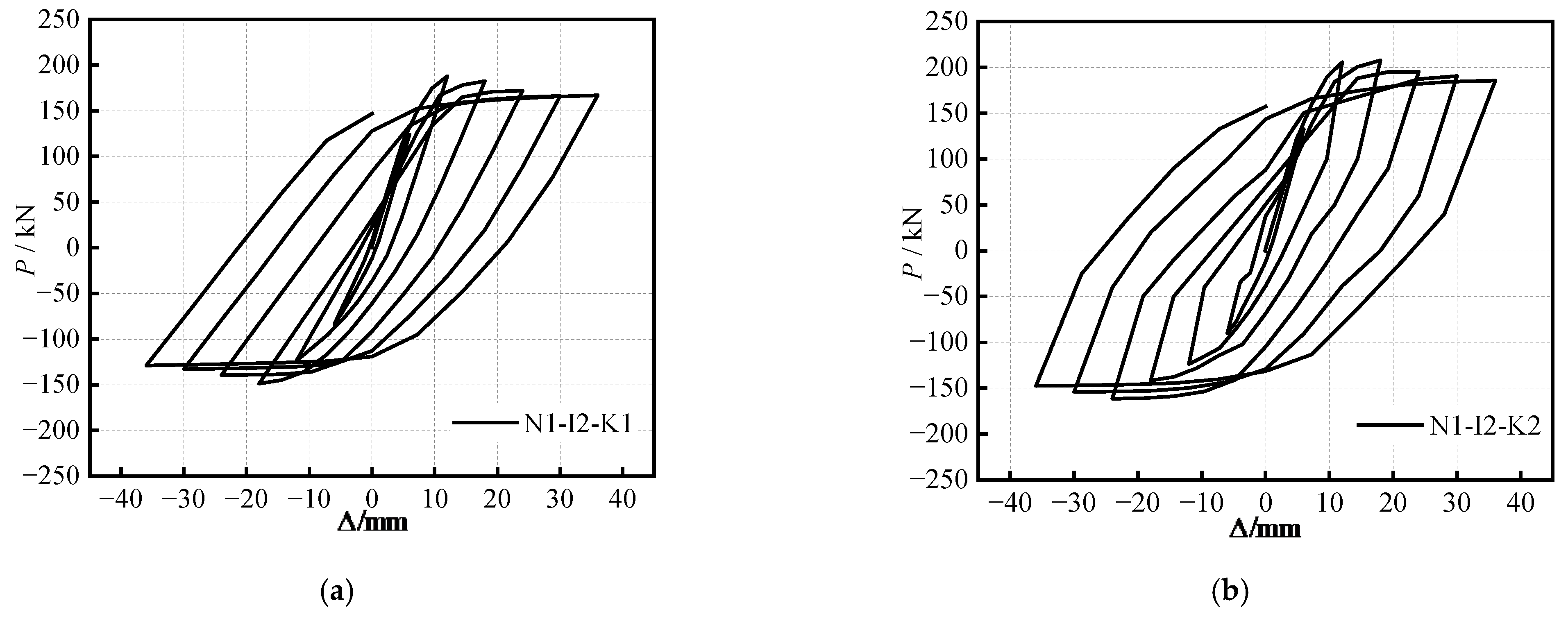
Eight parametric analysis models for the specimen were established as the various parameters based on the finite element model, axial compression ratio (
n), beam–column line stiffness ratio (
i), and yield bending moment ratio of the beam–column (
km), as shown in
Table 4. The concrete strength grade of the specimens was C40. In addition, by taking Nx-Ix-Kx as an example for the naming of the specimens, N1~N4, respectively, indicate the
n of 0.36, 0.20, 0.30, and 0.40; I1 ~ I3, respectively, indicate the (
i) of 0.62, 0.41, and 0.31; and K1~K3, respectively, indicate the (
km) of 0.10, 0.19, and 0.31.
6. Conclusions
This study established a finite element model with respect to the seismic behavior for the S-RACFST frame specimen. The seismic behavior of the eight S-RACFST frame finite element specimens was analyzed within the various design parameters. The sensitivity of the various design parameters on the seismic behavior of the S-RACFST frame was revealed via grey correlation analysis. The conclusions were as follows:
(1) The test curves agree with the finite element simulation curves of the S-RACFST frame that were developed by the ABAQUS software. The computational accuracy can meet the requirements, as well as address the response of the S-RACFST frame, which is effectively simulated under the seismic effects. Thus, the finite element model developed in this study is feasible with respect to the seismic behavior analysis of the S-RACFST frame.
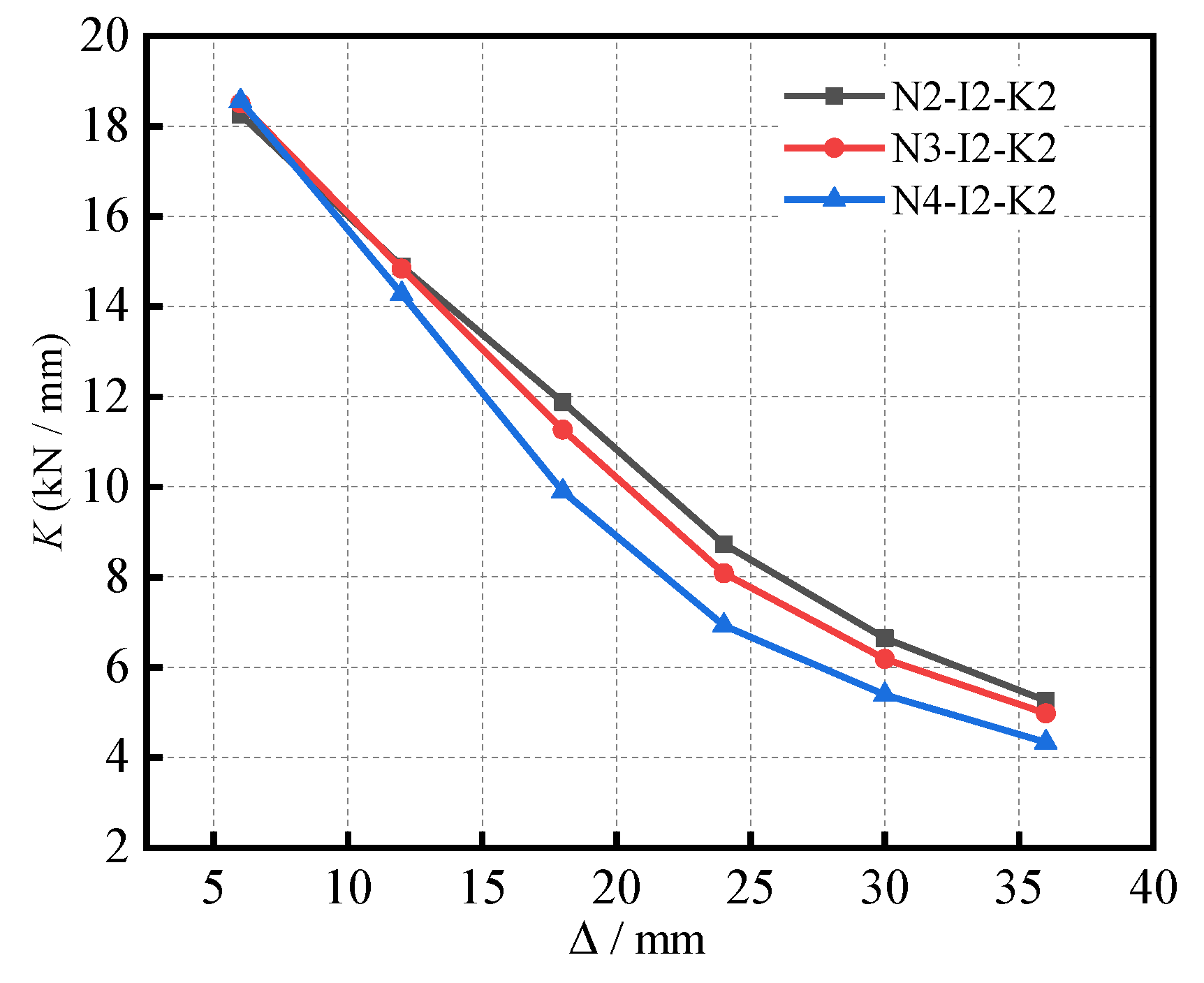
(2) With the axial compression ratio increasing from 0.2 to 0.4, the hysteretic curve of the specimen becomes fuller, the horizontal bearing capacity decreases gradually, and the displacement ductility coefficient increases by 28.5%. At the end of the loading phase, the equivalent viscous damping coefficient of 0.348 is obtained with respect to the specimens with an axial compression ratio of 0.4. The equivalent viscous damping coefficients of the specimen with the axial compression ratio of 0.4 were found to be 17.9% and 11.5% higher than that of the specimen with the axial compression ratio of 0.2 and the axial compression ratio of 0.3.
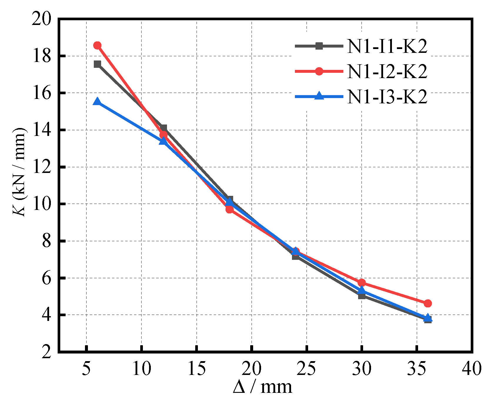
(3) With an increase in the beam–column line stiffness ratio, the hysteretic curves of the specimens show a full fusiform shape, and, subsequently, the load capacity gradually increases. At the end of the loading phase, all of the specimens’ equivalent viscous damping coefficients were found to be higher than those of the traditional reinforced concrete structures. The change in the displacement ductility coefficient was found to increase at first, then decrease. When the beam–column line stiffness ratio was at 0.41, a higher ductility within the range of changing parameters was found. The reason for this is due to the fact that the appropriate beam–column line stiffness ratio causes the beam to obtain a better transfer horizontal force, such that the two columns work well together; however, when it is too large, it will lead to a ductility reduction. Therefore, when the beam–column line stiffness ratio is appropriate, the frame can demonstrate good energy dissipation capacity.
(4) With the increase in the yield bending moment ratio of the beam–column from 0.10 to 0.31: the hysteretic curves of the specimens become fuller and fuller; the peak bearing capacities of the specimens increase; and the positive peak load and negative peak load increase by 16.4% and 22.8%, respectively. The displacement ductility coefficients were found to be close to three, thereby demonstrating good seismic performance. The stiffness curve of the specimen with a large yield bending moment ratio with respect to the beam–column was found to be significantly higher than that of the specimen with a small ratio. In addition, each specimen exhibited a great energy dissipation capacity. Furthermore, the results show that the variation in the yield bending moment ratio of the beam–column possesses a significant influence on the bearing capacity of the frame, such that the design requirements of the bearing capacity can be realized by designing the yield moment ratio of the beam–column in regard to engineering practice.
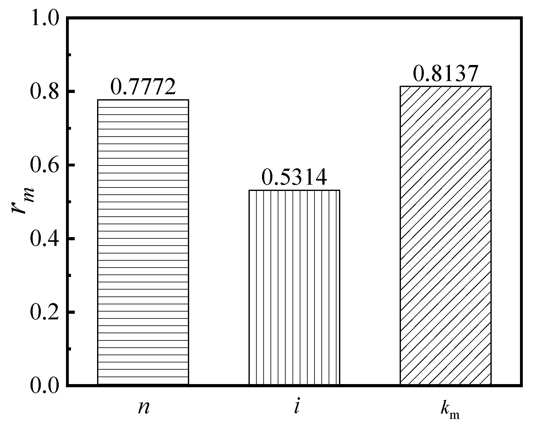
(5) According to the parameter sensitivity analysis, the beam–column yield bending moment ratio significantly influences the seismic behavior of the S-RACFST frame. It is recommended that the yield bending moment ratio of the beam–column be considered first in order to ensure the seismic behavior of the RACFST frame. Moreover, a higher load-bearing and deformation capacity can be achieved by selecting an appropriate yield bending moment ratio of the beam–column.
(6) This study shows that the S-RACFST frames possess an excellent seismic performance within the range of design parameters. The data parameters provided in this paper can be referred to when designing such frames in earthquake areas, thereby providing a reference for engineering designs.
The finite element model of the single-story and single-span structures established in this study is based on previous experiments, which can reflect the stress state of the actual structure to a certain extent. The single-story and single-span frame form is the most basic component unit. As such, the multi-story building frame can be regarded as the combination and superposition of single-story and single-span frames. Therefore, the experimental design of multi-story buildings can refer to the results of this study. After that, the hysteretic performance experiment of the multi-story building frame can be carried out. When such an effort is conducted, the finite element model of the multi-story building frame can then be established. The mechanical characteristics and failure laws of the multi-story building can be understanding.


