
Varnish Formation and Removal in Lubrication Systems: A Review


Abstract
1. Introduction
2. Varnish
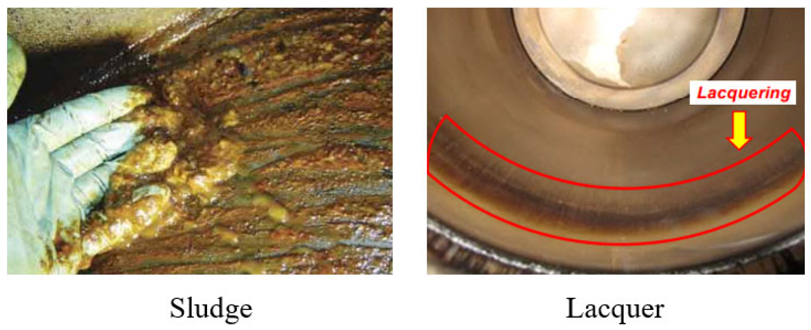
2.1. Definition and Characteristics
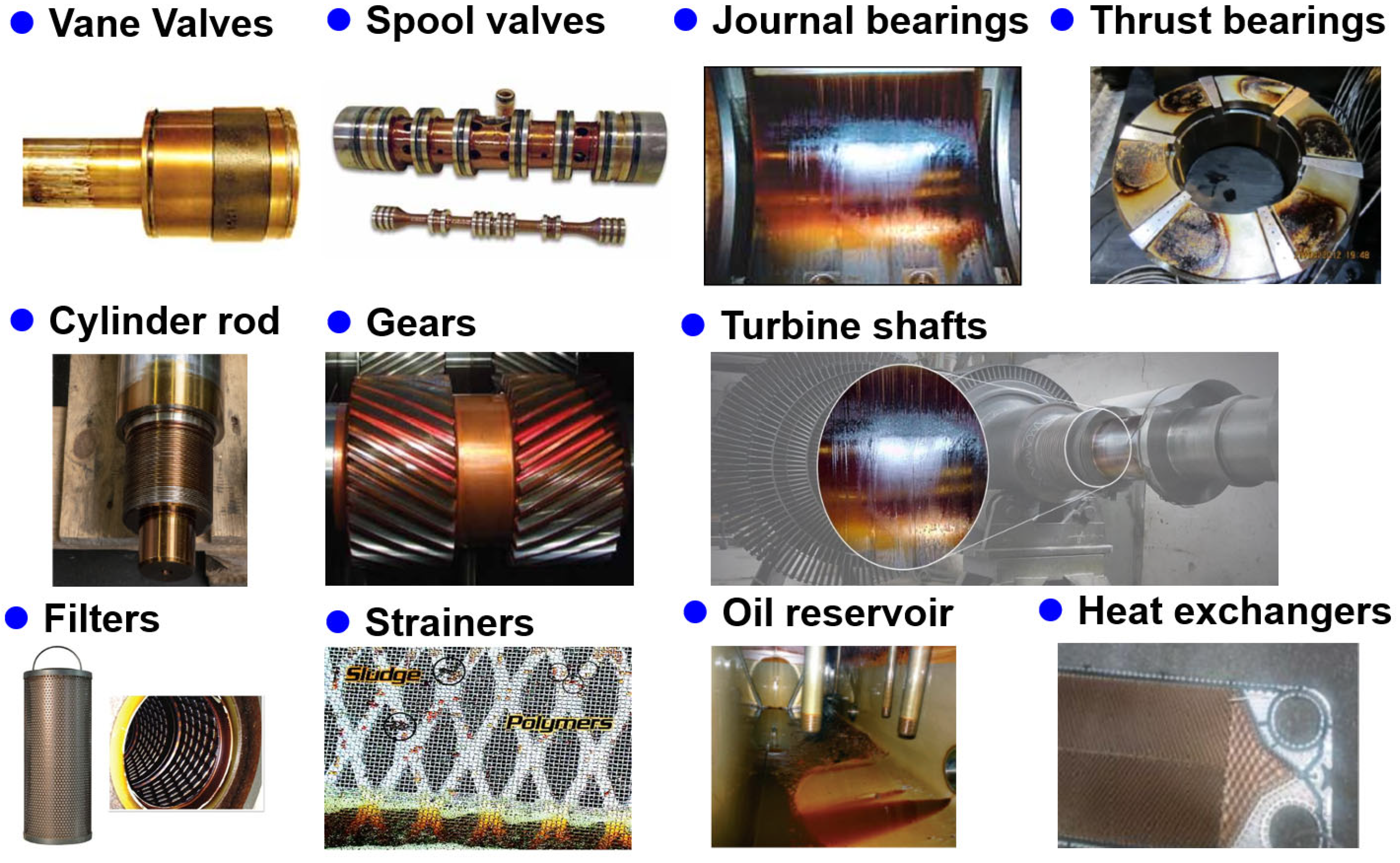
2.2. Varnish-Generating Machinery
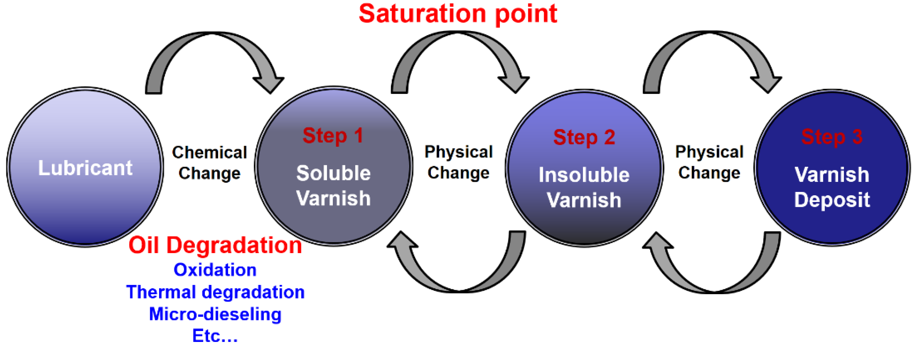
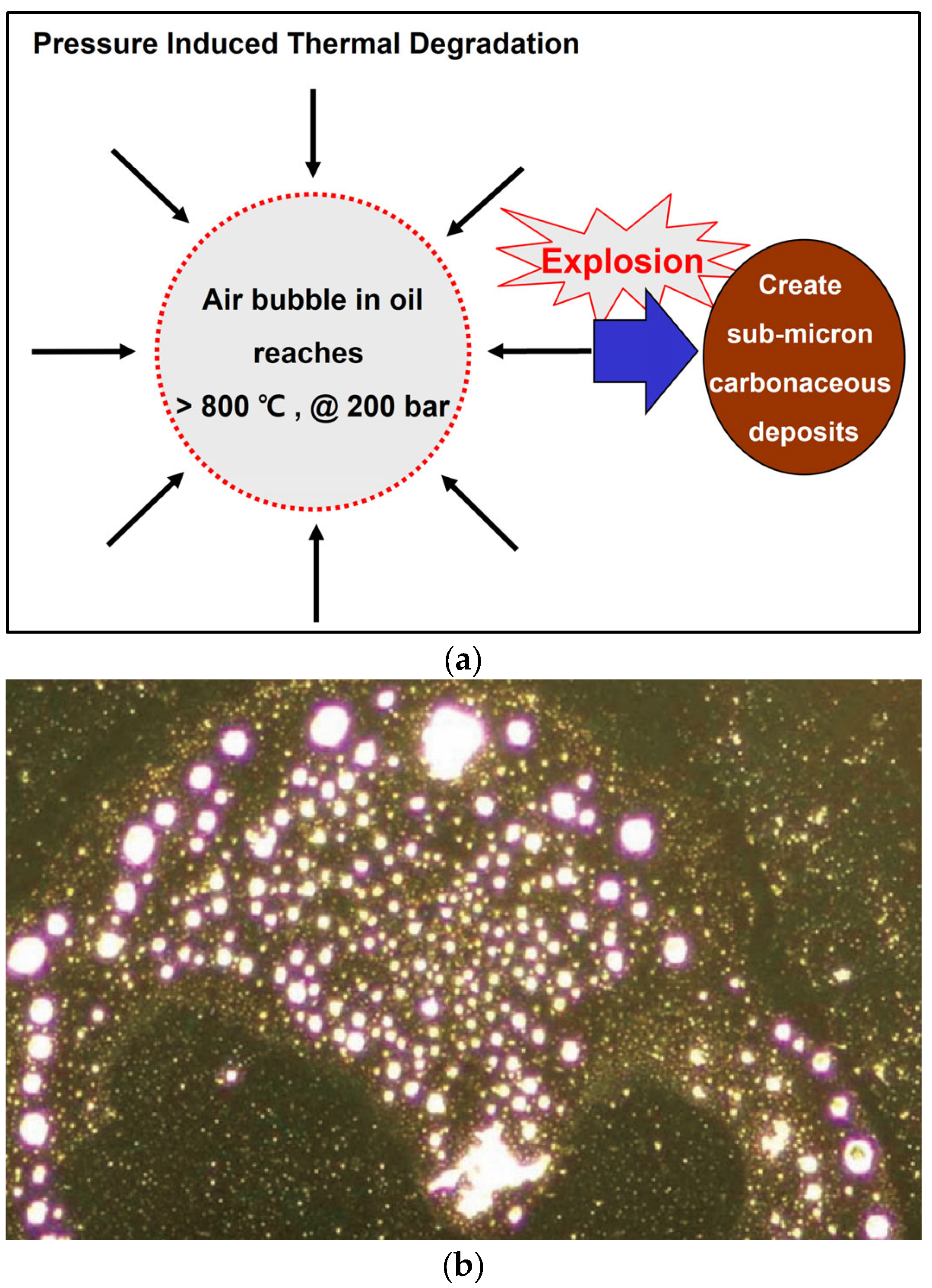
2.3. Generation Mechanism
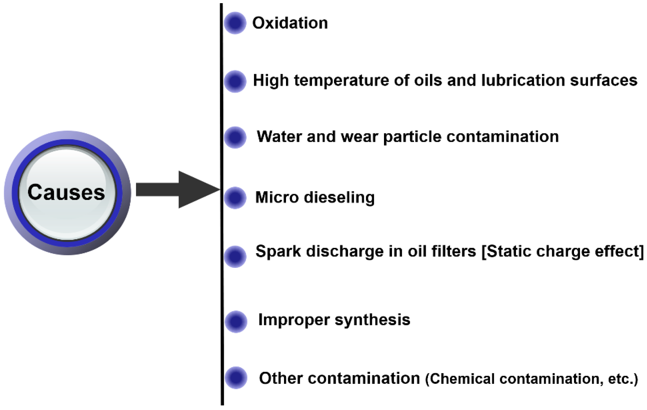
2.4. Causes
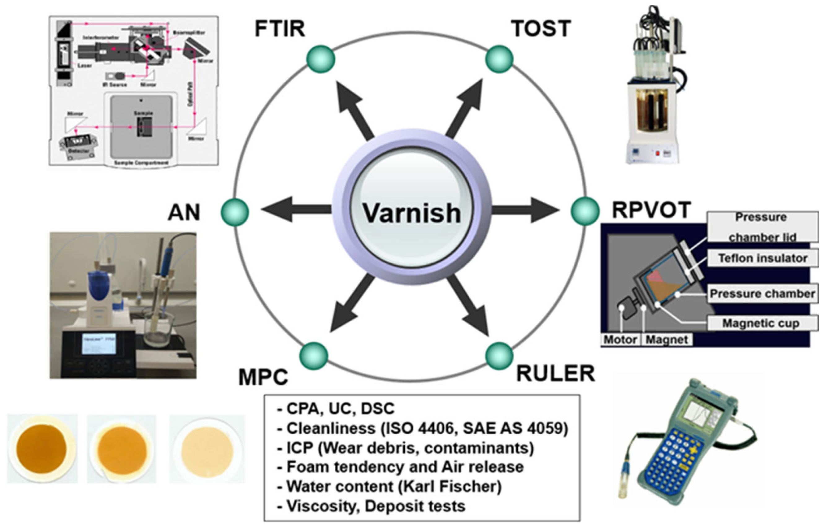
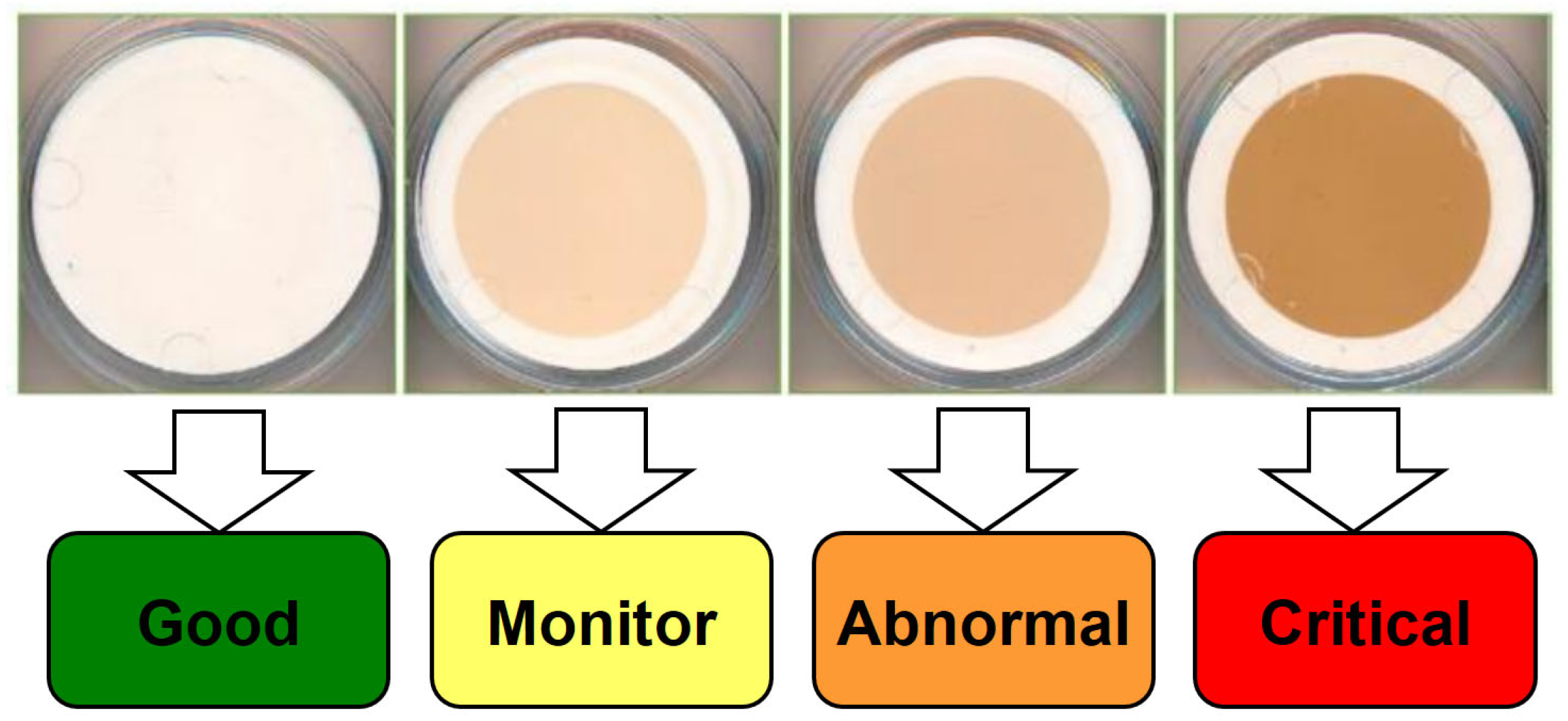
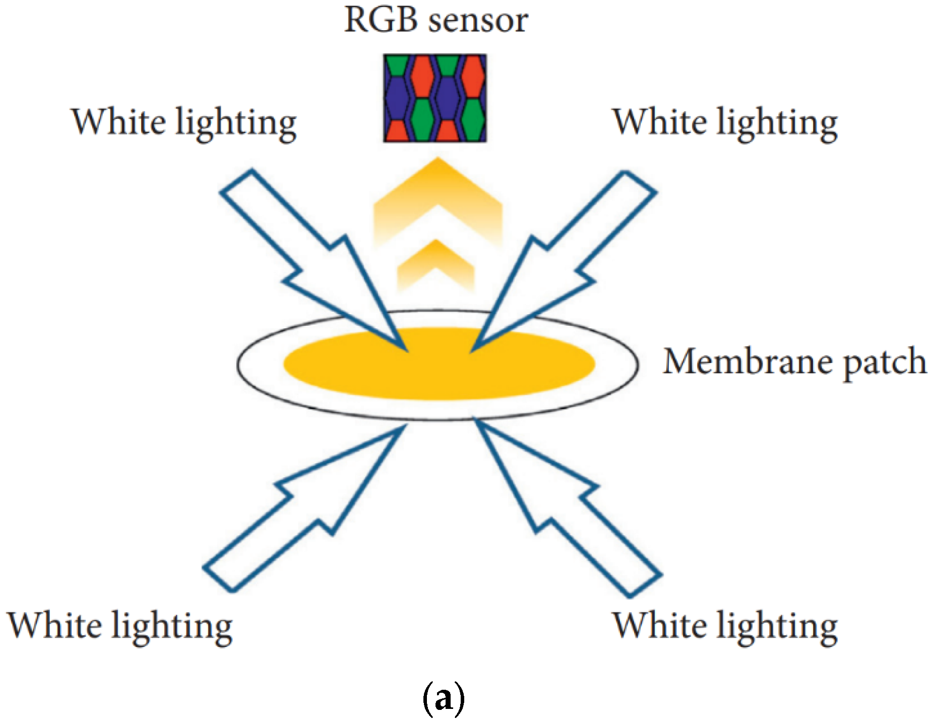
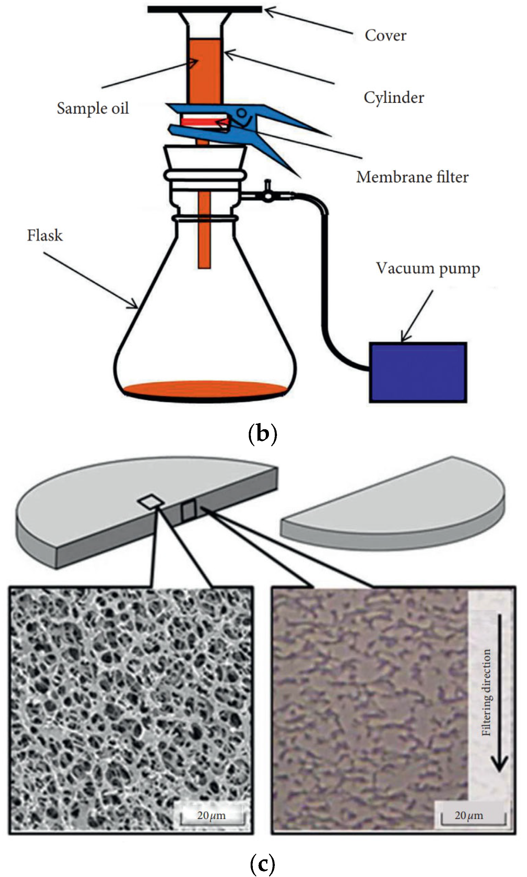
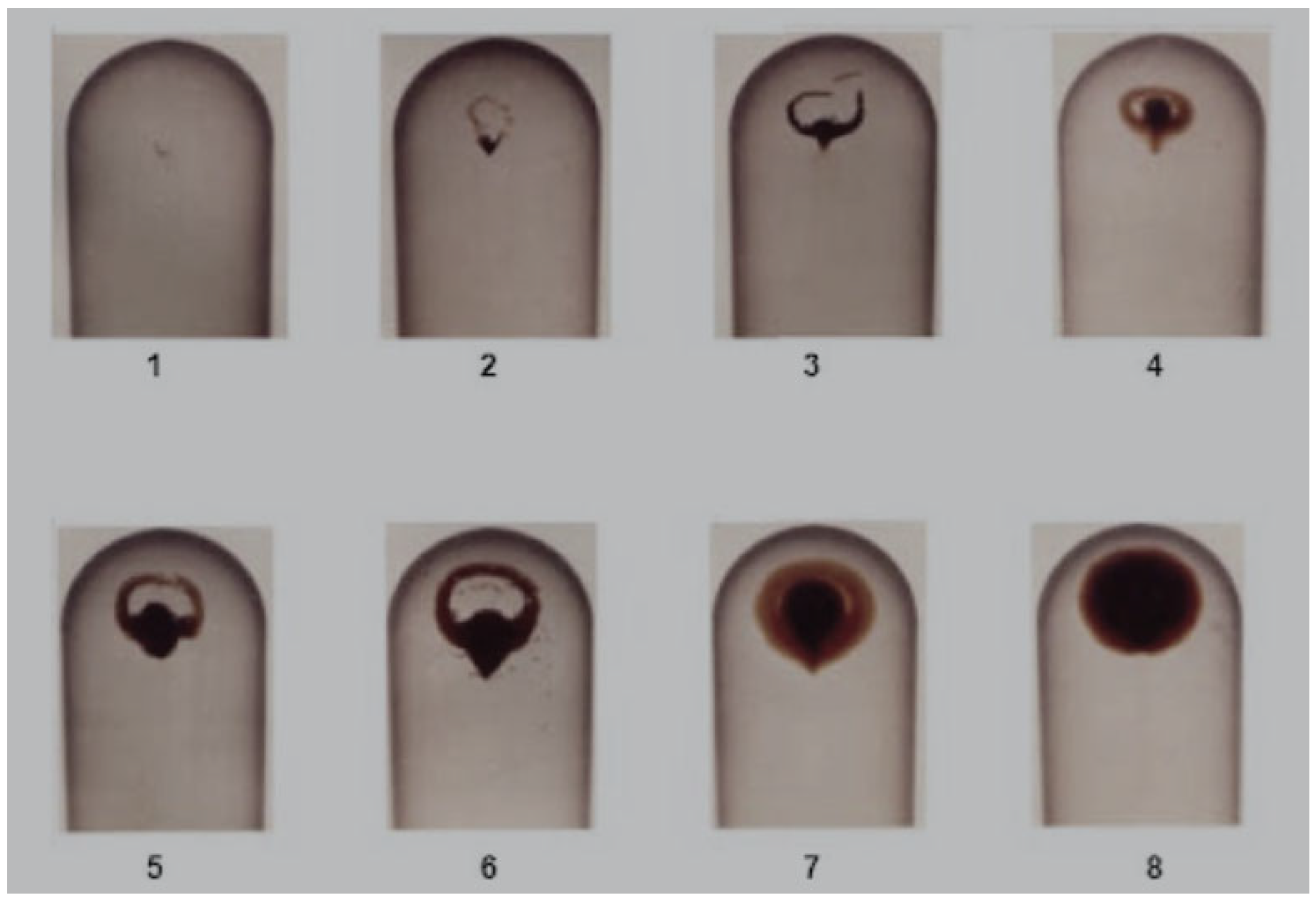
2.5. Measurement Methods
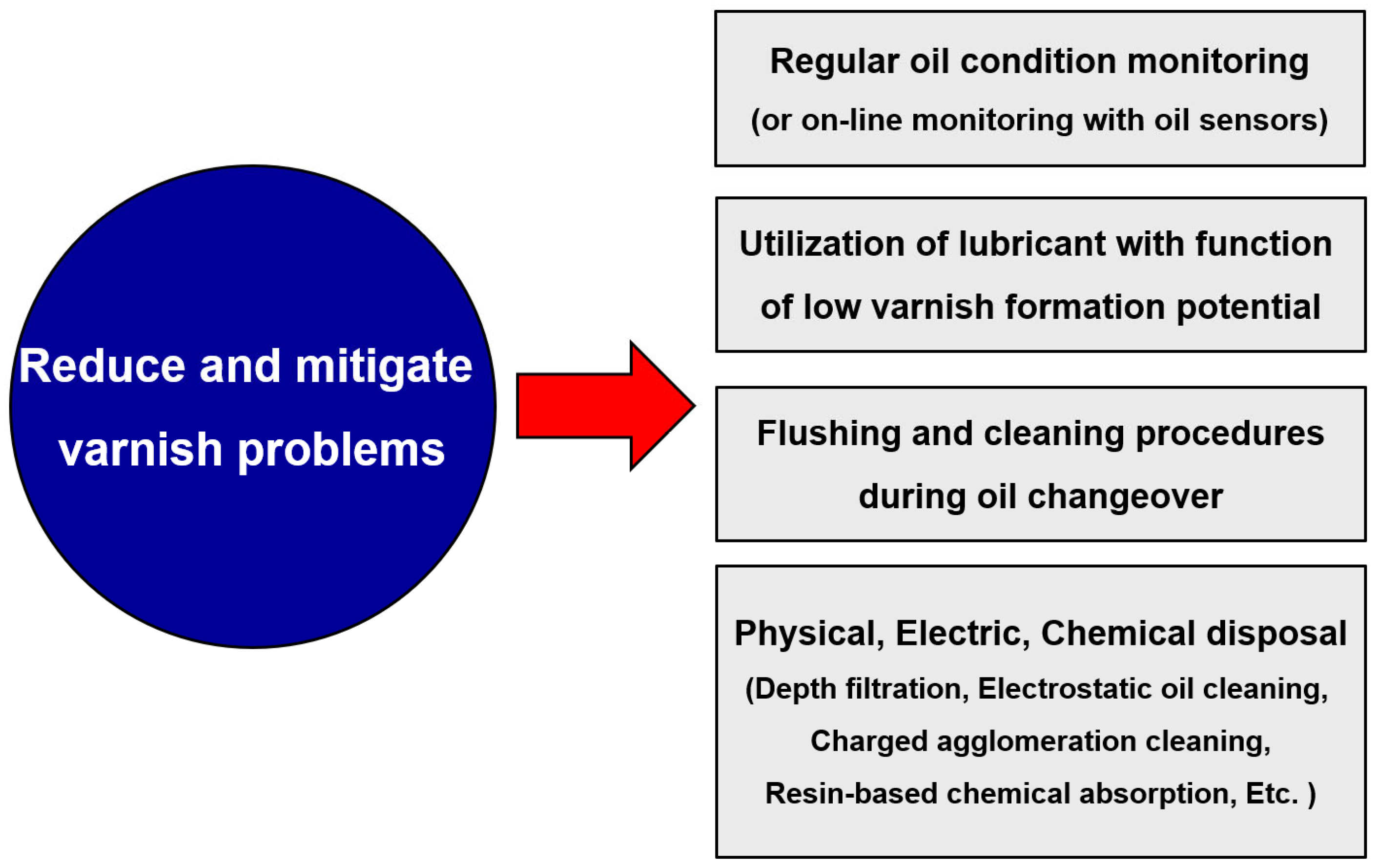
2.6. Prevention and Removal Methods
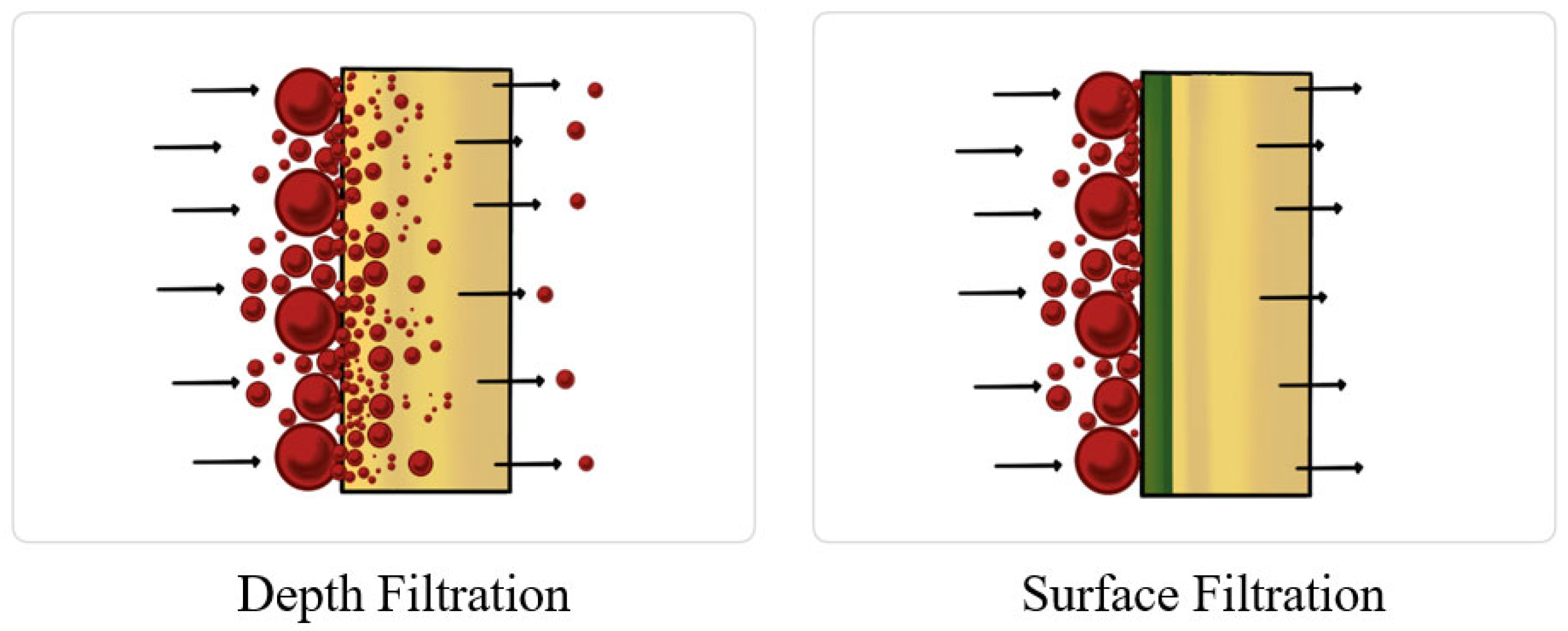
- Depth filtration
- 2.
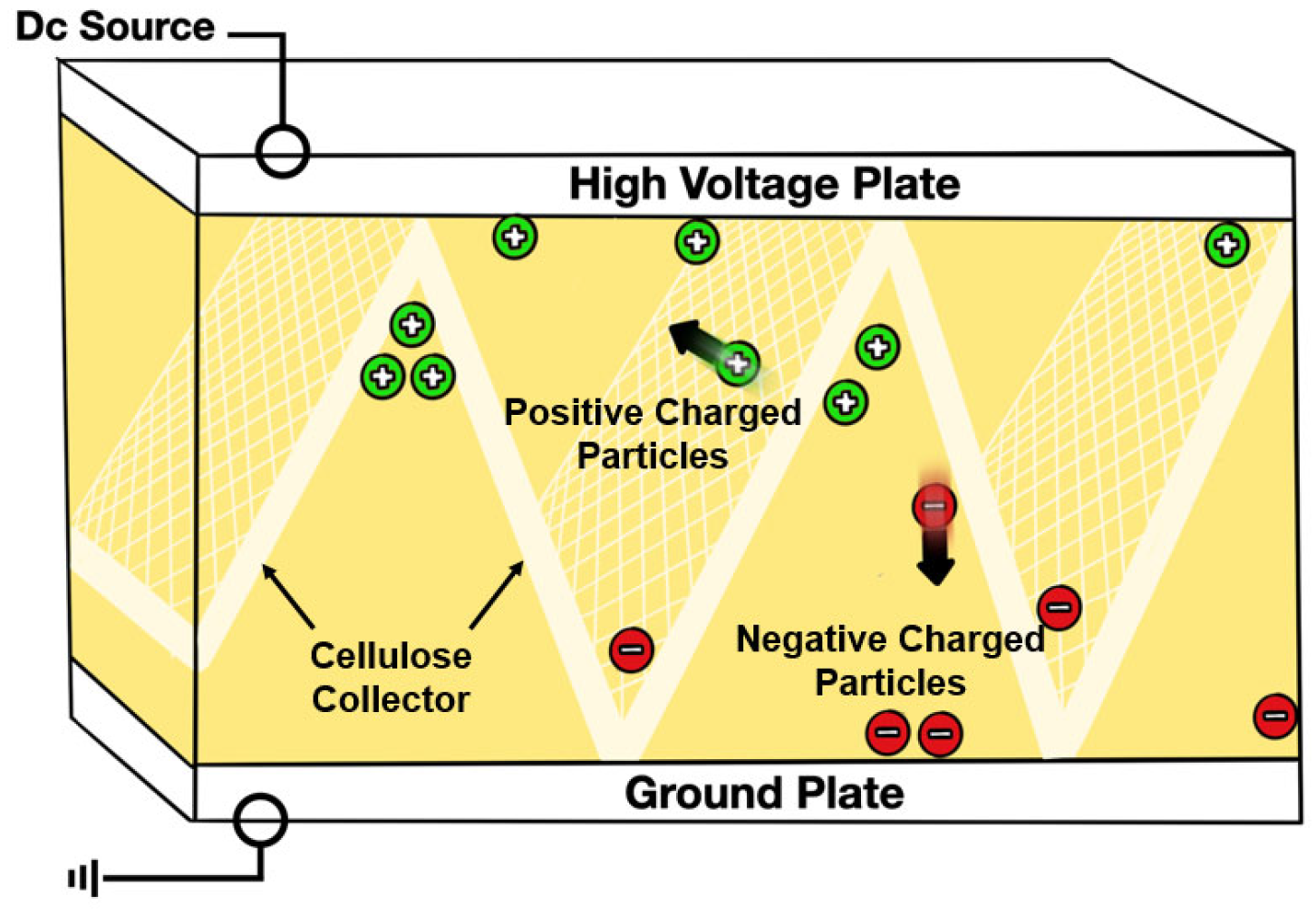
- Electrostatic oil cleaning
- 3.
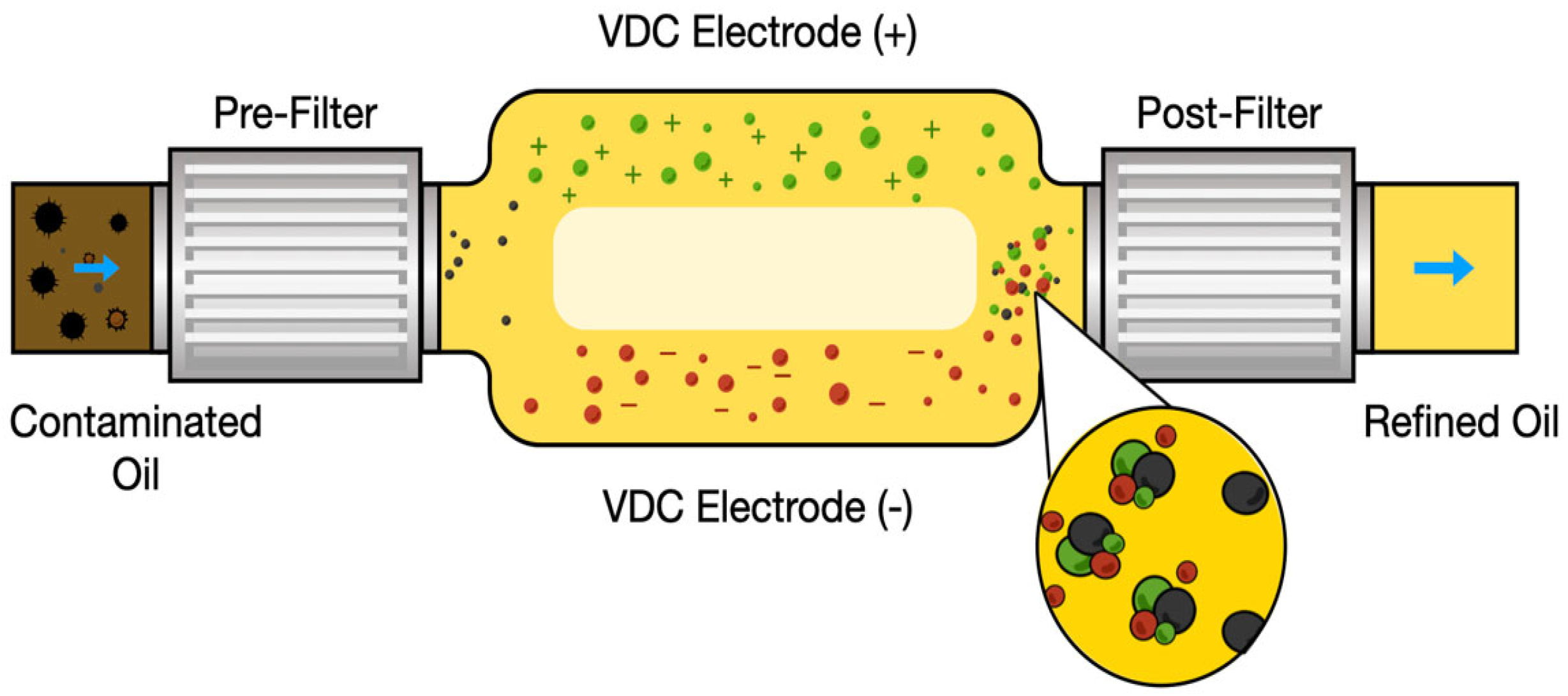
- Charged agglomeration cleaning
- 4.
- Resin-based chemical absorption
3. Conclusions
Author Contributions
Funding
Institutional Review Board Statement
Informed Consent Statement
Data Availability Statement
Acknowledgments
Conflicts of Interest
References
- Dai, W.; Kheireddin, B.; Gao, H.; Liang, H. Roles of nanoparticles in oil lubrication. Tribol. Int. 2016, 102, 88–98. [Google Scholar] [CrossRef]
- Hsu, S.M. Molecular basis of lubrication. Tribol. Int. 2004, 37, 553–559. [Google Scholar] [CrossRef]
- Singh, A.; Verma, N.; Mamatha, T.G.; Kumar, A.; Singh, S.; Kumar, K. Properties, functions and applications of commonly used lubricant additives: A review. Mater. Today Proc. 2021, 44, 5018–5022. [Google Scholar] [CrossRef]
- Wu, X.; Gong, K.; Zhao, G.; Lou, W.; Wang, X.; Liu, W. MoS2/WS2 quantum dots as high-performance lubricant additive in polyalkylene glycol for steel/steel contact at elevated temperature. Mater. Today Proc. 2018, 5, 1700859. [Google Scholar]
- Yu, W.; Xie, H. A review on nanofluids: Preparation, stability mechanisms, and applications. J. Nanomater. 2012, 2012, 435873. [Google Scholar] [CrossRef]
- Wang, R.; Wu, Q.; Wu, Y. Use of nanoparticles to make mineral oil lubricants feasible for use in a residential air conditioner employing hydrofluorocarbons refrigerants. Energy Build. 2010, 42, 2111–2117. [Google Scholar] [CrossRef]
- Yan, J.; Zhang, Z.; Kuriyagawa, T. Effect of nanoparticle lubrication in diamond turning of reaction-bonded SiC. Int. J. Autom. Technol. 2011, 5, 307–312. [Google Scholar] [CrossRef]
- Ali, M.K.A.; Fuming, P.; Younus, H.A.; Abdelkareem, M.A.A.; Essa, F.A.; Elagouz, A.; Xianjun, H. Fuel economy in gasoline engines using Al2O3/TiO2 nanomaterials as nanolubricant additives. Appl. Energy 2018, 211, 461–478. [Google Scholar] [CrossRef]
- Li, B.; Wang, X.; Liu, W.; Xue, Q. Tribochemistry and antiwear mechanism of organic-inorganic nanoparticles as lubricant additives. Tribol. Lett. 2006, 22, 79–84. [Google Scholar] [CrossRef]
- Luo, T.; Wei, X.; Zhao, H.; Cai, G.; Zheng, X. Tribology properties of Al2O3/TiO2 nanocomposites as lubricant additives. Ceram. Int. 2014, 40, 10103–10109. [Google Scholar] [CrossRef]
- Hernandez Battez, A.; Gonzalez, R.; Viesca, J.L.; Fernandez, J.E.; Diaz Fernandez, J.M.; Machado, A.; Chou, R.; Riba, J. CuO, ZrO2 and ZnO nanoparticles as antiwear additive on oil lubricants. Wear 2008, 265, 422–428. [Google Scholar] [CrossRef]
- Mujahid, A.; Dickert, F.L. Monitoring automotive oil degradation: Analytical tools and onboard sensing technologies. Anal. Bioanal. Chem. 2012, 404, 1197–1209. [Google Scholar] [CrossRef] [PubMed]
- Singh, H.; Swaroop, S. Oxidation behavior of base oils and their constituting hydrocarbon types. Prep. ACS Div. Petrol. Chem. 1997, 42, 218. [Google Scholar]
- Guan, L.; Feng, X.L.; Xiong, G.; Xie, J.A. Application of dielectric spectroscopy for engine lubricating oil degradation monitoring. Sens. Actuators A Phys. 2011, 168, 22–29. [Google Scholar] [CrossRef]
- Muhammad, U.; Muhammad, W.S.; Syed, S.; Jamal, U.; Ahmad, N.; Zain, U.H. SI engine performance, lubricant oil deterioration, and emission: A comparison of liquid and gaseous fuel. Adv. Mech. Eng. 2020, 12, 1687814020930451. [Google Scholar]
- External Contaminants in Lubricating Oils: A Common but Critical Problem. Available online: https://blog.atten2.com/en/external-contaminants-in-lubricating-oils-a-common-but-critical-problem (accessed on 17 January 2023).
- Mohammed, R.S.; Ammar, H.; Louis, F. Effect of lubricant contamination on gear wear. Tribol. Lett. 2007, 27, 119–126. [Google Scholar]
- 10 Things You Should Know about Varnish. Available online: https://www.machinerylubrication.com/Read/30449/professional-certification-benefits (accessed on 18 January 2023).
- Sludge and Varnish in Turbines System. Available online: https://www.machinerylubrication.com/Read/874/sludge-varnish-turbine (accessed on 18 January 2023).
- Pashai, E.; Dehghani, M.R.; Feyzi, F. Observations of sludge formation in group I base stock for lubricants and thermodynamic modeling with the SAFT equation of state. Iran. J. Chem. Eng. 2017, 14, 33–47. [Google Scholar]
- Hong, S.H. A literature review of lacquer formation in medium-speed and low-speed engines. J. Mech. Sci. Technol. 2016, 30, 5651–5657. [Google Scholar] [CrossRef]
- Vanquish Varnish to Improve Gas Turbine Reliability, 2011 Outage Handbook-Lubricating/Control Oil. Available online: https://www.ccj-online.com/special-issue-2011-outage-handbook/2011-outage-handbook-lubricating-control-oil/ (accessed on 18 January 2023).
- Hobbs, M.G.; Dufresne, P.T., Jr. Lubricant Varnishing and Varnish Mitigation. In Proceedings of the LUBMAT 2014, Lubrication, Maintenance and Tribotechnology Conference & Exhibition, Manchester, UK, 25–27 June 2014; p. L141082. [Google Scholar]
- Prasad, S. Formulating low varnish turbine technology: Lubricant additives with improved deposit control. Tribol. Lubr. Technol. 2013, 69, 44–46. [Google Scholar]
- Lube-Oil Maintenance: Lubricant Varnishing and Mitigation Strategies. Available online: https://www.ccj-online.com/4q-2013/lube-oil-maintenance-lubricant-varnishing-and-mitigation-strategies/ (accessed on 29 January 2023).
- Lube Oil Varnish Control. Available online: https://www.efficientplantmag.com/2007/03/lube-oil-varnish-control/ (accessed on 29 January 2023).
- Johnson, M.; Livingstone, G. Identifying Varnish and Oxidation Precursors in Lubricant Sumps. Tribol. Lubr. Technol. 2011, 67, 22–27. [Google Scholar]
- Discovering the Root Cause of Varnish Formation. Available online: https://www.machinerylubrication.com/Read/998/varnish-formation (accessed on 28 January 2023).
- Livingstone, G.; Oakton, D. The Emerging Problem of Lubricant Varnish. Maint. Asset Manag. 2010, 25, 38–42. [Google Scholar]
- Varnish Contamination in Hydraulic & Lube Oil Systems. Available online: https://digitaleditions.walsworth.com/publication/?i=346359&article_id=2609332&view=articleBrowser (accessed on 29 January 2023).
- Kishline, F.F. A Symposium on Varnish in Engines. SAE Trans. 1939, 34, 321–324. [Google Scholar]
- Jordan, L. Lubricant Varnish: What It Is, How It Forms and How to Mitigate It. Available online: Ttps://therigteam.com/wp-content/uploads/2019/09/7122019-RIG-Lubricant-Varnish.pdf (accessed on 8 February 2023).
- Plants & Facilites, Avoiding Varnish-Related Shutdowns with Routine and Advanced Tests. Available online: https://www.lubesngreases.com/magazine/28_8/avoiding-varnish-related-shutdowns-with-routine-and-advanced-tests/ (accessed on 11 February 2023).
- Dilectrophoresis. Available online: https://en.wikipedia.org/wiki/Dielectrophoresis (accessed on 11 February 2023).
- Tracking Varnish Formation in Turbomachinery, Technical Brochure. Available online: https://certasenergylubricants.com/wp-content/uploads/2019/12/Turbine-varnish-formation_whitepaper.pdf (accessed on 11 February 2023).
- Kon, T.; Honda, T.; Sasaki, A. Estimation of the oxidative deterioration of turbine oil using membrane patch color. Adv. Tribol. 2020, 2020, 1708408. [Google Scholar] [CrossRef]
- Day, L. Solving varnish problems in gas turbine lubricants. Tribol. Lubr. Technol. 2008, 64, 32–38. [Google Scholar]
- The Unvarnished Truth about Varnish. Available online: https://www.stle.org/files/TLTArchives/2016/11_November/Feature.aspx (accessed on 11 February 2023).
- Why Varnish Removal Fails: The Soluble-Insoluble Varnish Equilibrium. Available online: http://proactivereliability.files.wordpress.com/2017/06/why-varnish-removal-fails_the-soluble-insoluble-varnish-equilibrium1.pdf (accessed on 11 February 2023).
- Sitton, A.; Ameye, J.; Kauffman, R.E. Residue analysis on RPVOT test samples for single and multiple antioxidants chemistry for turbine lubricants. J. ASTM Int. 2006, 3, 13508. [Google Scholar] [CrossRef]
- Water Contamination of Lube Oils. Available online: https://www.machinerylubrication.com/Read/1379/contaminating-oil (accessed on 12 February 2023).
- Bilson, S. Contamination control in hydraulic and lubrication systems of paper industries: An Overview. IPPTA J. 2010, 22, 151–155. [Google Scholar]
- The Real Reasons Why Hydraulic Fluids Fail. Available online: https://www.stle.org/images/pdf/STLE_ORG/BOK/LS/Hydraulics/The%20Real%20Reasons%20Hydraulic%20Fluids%20Fail_July15%20TLT.pdf (accessed on 12 February 2023).
- Khemchandani, G. Non-varnishing and tribological characteristics of polyalkylene glycol-based synthetic turbine fluid. Lubr. Sci. 2012, 24, 11–21. [Google Scholar] [CrossRef]
- Sasaki, A.; Uchiyama, S.; Yamamoto, T. Generation of static electricity during filtration. Lubr. Eng. 1999, 55, 14–21. [Google Scholar]
- Sasaki, A.; Uchiyama, S.; Yamamoto, T. Free radicals and oil auto-oxidation due to spark discharges of static electricity. Lubr. Eng. 1999, 55, 24–27. [Google Scholar]
- ASTM D7843-16; Standard Test Method for Measurement of Lubricant Generated Insoluble Color Bodies in In-Service Turbine Oils using Membrane Patch Colorimetry, Book of ASTM Standards. ASTM International: West Conshohocken, PA, USA, 2016.
- Tomohico, K.; Honda, T.; Sasaki, A. Influence of solvents, oil temperature, and incubation period on membrane patch color. Tribol. Online 2018, 13, 225–231. [Google Scholar]
- Learn Oil Analysis. Available online: https://learnoilanalysis.com/lube-oil-test-analysis-lab-lubrication-reliability-maintenance/oxidation-stability-by-ruler-rpvot (accessed on 13 February 2023).
- Cryil, A.M. The influence of hindered phenolic and aromatic amine antioxidants on the stability of base oils. In Proceedings of the 213th National Meeting American Chemical Society, San Francisco, CA, USA, 13–17 April 2007. [Google Scholar]
- Bolisetty, M.N.K.P.; Tripathi, C.; Mondal, S.; Rai, K.; Harinarain, A.K.; Saxena, D.; Ramakumar, S.S.V. Simulating compressor oil oxidative performance using laboratory oxidation test methodology for development of long life compressor oil. Res. Sq. 2022. [Google Scholar] [CrossRef]
- Novotny-Fartny, F.; Baumann, K.; Leimeter, T. Optimizing the thermos-oxidation stability of gas turbine oils. Gorva Maz. 2008, 47, 209–231. [Google Scholar]
- Dry TOST, Deposit Control Test Method. Available online: https://www.mobil.ca/en-ca/lubricants/industrial/lubricant-expertise/resources/dry-tost-test-methods (accessed on 18 February 2023).
- Nagy, A.L.; Agocs, A.; Ronai, B.; Raffai, P.; Rohde-Brandenburger, J.; Besser, C.; Dorr, N. Rapid fleet condition analysis through correlating basic vehicle tracking data with engine oil FT-IR spectra. Lubricants 2021, 9, 114. [Google Scholar] [CrossRef]
- Abdul-Munaim, A.M.; Holland, T.; Sivakumar, P.; Watson, D.G. Absorption wavebands for discriminating oxidation time of engine oil as detected by FTIR spectroscopy. Lubricants 2019, 7, 24. [Google Scholar] [CrossRef]
- Holland, T.; Abdul-Munaim, A.M.; Watson, D.G.; Sivakumar, P. Influence of sample mixing techniques on engine oil contamination analysis by infrared Spectroscopy. Lubricants 2019, 7, 4. [Google Scholar] [CrossRef]
- Song, X.; Xu, W.; Cai, B.; Wang, L.; Luo, Z.; Wang, B. A DOPO-bases compound containing aminophenyl silicon oil for reducing fire hazards of polycarbonate. Materials 2023, 16, 1449. [Google Scholar] [CrossRef]
- Claire, M.; Serge, A.; Guy, R.; Sylvie, M.C.; Olivier, N.; Marie-Florence, G.L. Characterisation and quantification of lubricants in a cross-linkable varnish by Fourier transform infrared absorption spectroscopy (FT-IR) and differential scanning calorimetry. Polym. Polym. Compos. 2007, 15, 83–90. [Google Scholar] [CrossRef]
- Frilette, V.J. Drying oil and oleoresinous varnish films. Increase in acidity on aging. Ind. Eng. Chem. 1946, 38, 493–496. [Google Scholar] [CrossRef]
- Pulsifer, L.V. Automoble finishing-varnish. SAE Trans. 1923, 18, 466–503. [Google Scholar]
- Chokelarb, W.; Assawasaengrat, P.; Sitton, A.; Sirisithichote, T.; Sriprom, P. Soluble and insoluble varnish test methods for trending varnish buildup in mineral turbine oil. J. Jpn. Inst. Energy 2022, 101, 242–250. [Google Scholar] [CrossRef]
- Tanis Engineering. Available online: https://tanis-engineering.nl/en/advice/types-of-analysis/ (accessed on 18 February 2023).
- Chen, M.; Wang, C. Quick coker test: A new and rapid engine oil detergency and thermos-oxidation test. Sci. China Ser. A 2001, 44, 472–477. [Google Scholar]
- Xie, J.; Chen, X.; Peng, C. Evaluation of the detergency of diesel engine oil with heat tube oxidation method I. Detergency of CC grade engine oil. Pet. Process. Sect. 1995, 11, 98–103. [Google Scholar]
- Xie, J.; Chen, X.; Wang, J. Evaluation of the detergency of diesel engine oil with heat tube oxidation method II. Detergency of CD grade engine oil. Pet. Process. Sect. 1995, 11, 104–107. [Google Scholar]
- Alberola, N.; Vassel, A.; Bourgognon, H.; Rodes, C. The microcoking ELF/ECL test a new lubricant thermos-oxidation test based on original design. Lub. Eng. 1990, 47, 480–484. [Google Scholar]
- Hong, S.H.; Ju, S.H. Effective test of lacquer in marine diesel engines. Int. J. Nav. Archit. Ocean Eng. 2017, 9, 199–208. [Google Scholar] [CrossRef]
- Hong, S.H.; Jeon, H.G. Assessment of condition diagnosis system for axles with ferrous particle sensor. Materials 2023, 16, 1426. [Google Scholar] [CrossRef] [PubMed]
- Hong, S.H.; Jeon, H.G. Monitoring the conditions of hydraulic oil with integrated oil sensors in construction equipment. Lubricants 2022, 10, 278. [Google Scholar] [CrossRef]
- Jeon, H.G.; Kim, J.K.; Na, S.J.; Kim, M.S.; Hong, S.H. Application of condition monitoring for hydraulic oil using tuning fork sensor: A study case on hydraulic system of earth moving machinery. Materials 2022, 15, 7657. [Google Scholar] [CrossRef]
- Huang, Z.; Chen, Q.; Yao, Y.; Chen, Z.; Zhou, J. Micro-bubbles enhanced removal of diesel oil from the contaminated soil in washing/flushing with surfactant and additives. J. Environ. Manag. 2021, 290, 112570. [Google Scholar] [CrossRef]
- Burger, D.R. Measuring and Treating Varnish Formation in Turbine Oils. Available online: https://www.wearcheck.co.za/shared/TB62.pdf (accessed on 20 February 2023).
- Varnish Removal Solutions: How Effective Are They? Available online: https://www.caltex.com.sa/en_sa/home/learning/about-our-brands/vartech/varnish-removal-solutions.html (accessed on 21 February 2023).
- Farooq, K. Varnish removal and control in turbine lubrication systems. In Proceedings of the ASME Power Conference, Albuquerque, NM, USA, 21–23 July 2009. [Google Scholar]
- Mobil™ System Cleaner. Available online: https://www.mobil.com/en-us/industrial/pds/gl-xx-mobil-system-cleaner (accessed on 21 February 2023).
- Boost VR+ Oil Varnish Removal Solution—Fluitec. Available online: https://www.fluitec.com/solutions/fluid-enhancement/boost-vr-varnish-removal/ (accessed on 21 February 2023).
- Kim, S.; Cho, H.; Hwang, W. Robust superhydrophilic depth filter and oil/water separation device with pressure control system for continuous oily water treatment on a large scale. Sep. Purif. Technol. 2021, 256, 117779. [Google Scholar] [CrossRef]
- Johnson, D. Characterizing Chemical Cleaners Used in Removing Varnish in Gas Turbine Engines. Ph.D. Thesis, University of California, Merced, CA, USA, 2018. [Google Scholar]
- How Electrostatic Filters Control Varnish, Noria. Available online: https://www.machinerylubrication.com/Read/28839/electrostatic-filters-varnish (accessed on 21 February 2023).
- Varnish Removal Unit, VRU. Available online: https://www.cjc.dk/products/varnish-removal-unit-vru/ (accessed on 21 February 2023).
- Patented VARNISH Removal Electrostatic Filters. Available online: https://oilkleen.com/oil-filtration/ (accessed on 21 February 2023).
- SMR Series. Available online: https://www.parker.com/content/dam/Parker-com/Literature/Hydraulic-Filter/HFD_Catalog/HFD_Catalog_SMR.pdf (accessed on 21 February 2023).
- Sentry System for Varnish Removal. Available online: https://shop.pall.com/us/en/power-generation/steam-plants/turbine-lubrication-1/zidhhtg8z2y (accessed on 21 February 2023).


| Panel Coker [63] | Hot Tube [64,65] | Sliding Ring [63] | Micro-Coking [66] | Quick Coker [63] | HHI Test [67] | |
|---|---|---|---|---|---|---|
| Test temp. | 310–330 °C | 300 °C | 300–350 °C | 330 °C | 330 ± 10 °C | 220 ± 5 °C |
| Oil temp. | 100 °C | - | 125–130 °C | - | - | - |
| Oil film forming | Splash | Cycling in hot tub | Splash | Temperature gradient | Drop | Pour |
| Sample volume (mass) | 250 mL | 5 g | 250 mL | 0.05 mL | 10 mL | 10 mL |
| Oxygen flow | - | 1.4 mL/min | - | - | - | - |
| Measurement parameters | Varnish merit | Deposit merit | Varnish merit | Time of deposit forming | Varnish merit | Deposit and pull-off pressure |
| Test time | 6 h | 4 h | 2 h | Several hours | 2.5–4 min | 20 ± 5 min |
| Set-up cost | High | High | High | Low | Low | Low |
| Technologies | Chemical Cleaning | Solvency Enhancer |
|---|---|---|
| Product (Manufacturer) | Mobil™ System Cleaner (ExxonMobil) [75] | BOOST VR+ (Fluitec) [76] |
| Kinematic Viscosity @40 °C | 55 mm2/s | 54 mm2/s |
| Density @15 °C | 0.926 kg/m3 | 0.86 kg/m3 |
| Appearance | Clear Brown | White |
| Flash Point | 138 °C | 233 °C |
| Technology | Depth Filtration | Electrostatic Oil Cleaning | Charge Agglomeration Cleaning | Resin Based Chemical Absorption |
|---|---|---|---|---|
| Product (Manufacturer) | Varnish Removal Unit with Varnish Removal insert 27/27 Filter Insert (CJC) [80] | Green Macheen™ 300 (Oilkleen) [81] | SMR 10 (Parker) [82] | Pall Sentry™ (PALL) [83] |
| Oil Reservoir Volume, max. | 45,000 L | 38,000 L | - | - |
| Oil Viscosity | 68 mm2/s | 100 mm2/s | 220 mm2/s | 500 mm2/s |
| Flow Rate, max. | 32 L/min | 20.52 L/min | 38 L/min | 11.36 L/min |
| Varnish Holding Capacity | 8 kg | 9 kg | - | - |
| Max. Oil Temperature | 105 °C | 82 °C | 93 °C | 59.4 °C |
| Design Pressure | 4 bar | - | 3.4 bar | 5.4 bar |
| Filtration Resolution | 3 µm | 0.01 µm | 5 µm | 12 µm |
Disclaimer/Publisher’s Note: The statements, opinions and data contained in all publications are solely those of the individual author(s) and contributor(s) and not of MDPI and/or the editor(s). MDPI and/or the editor(s) disclaim responsibility for any injury to people or property resulting from any ideas, methods, instructions or products referred to in the content. |
© 2023 by the authors. Licensee MDPI, Basel, Switzerland. This article is an open access article distributed under the terms and conditions of the Creative Commons Attribution (CC BY) license (https://creativecommons.org/licenses/by/4.0/).
Share and Cite
Hong, S.-H.; Jang, E.K. Varnish Formation and Removal in Lubrication Systems: A Review. Materials 2023, 16, 3737. https://doi.org/10.3390/ma16103737
Hong S-H, Jang EK. Varnish Formation and Removal in Lubrication Systems: A Review. Materials. 2023; 16(10):3737. https://doi.org/10.3390/ma16103737
Chicago/Turabian StyleHong, Sung-Ho, and Eun Kyung Jang. 2023. "Varnish Formation and Removal in Lubrication Systems: A Review" Materials 16, no. 10: 3737. https://doi.org/10.3390/ma16103737
APA StyleHong, S.-H., & Jang, E. K. (2023). Varnish Formation and Removal in Lubrication Systems: A Review. Materials, 16(10), 3737. https://doi.org/10.3390/ma16103737