
Investigation of the Technological Possibility of Manufacturing Volumetric Shaped Ductile Cast Iron Products in Open Dies


Abstract
1. Introduction
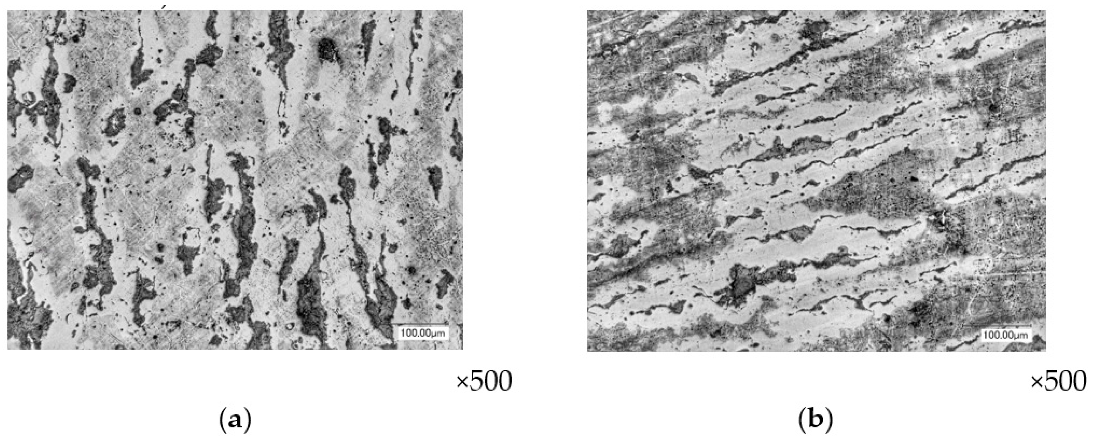
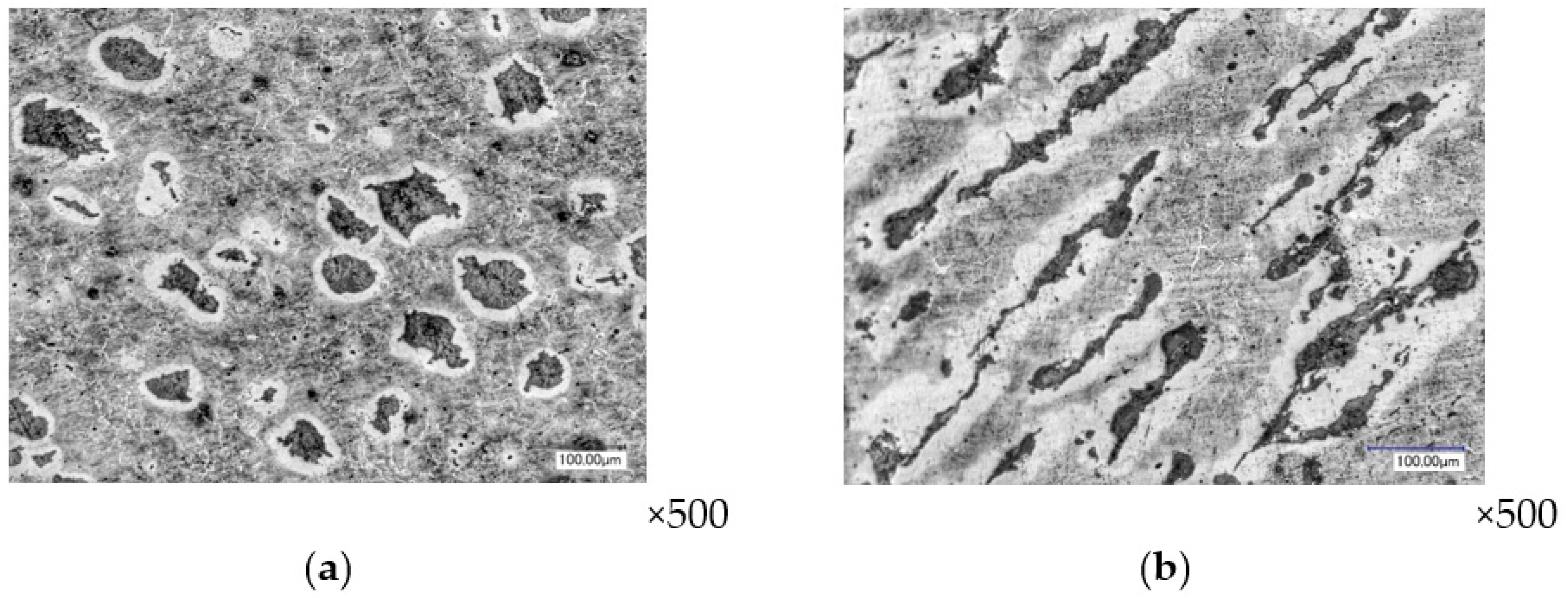
- Depending on the mechanical deformation scheme implemented, graphite inclusions of cast iron acquire a different shape: a disc-shaped shape under precipitation conditions, an elongated shape during extrusion [11].
- Studies of plastic deformation of cast iron under conditions of complex loading are rationally carried out using technological samples in which deformation schemes are implemented in relation to the manufacture of a certain class of products [15].
- The plastic flow of brittle graphite inclusions inside a metal matrix must be performed under conditions of uneven all-round compression; however, it is possible to use deformation schemes with the presence of tensile stresses [16,17]. As a confirmation of the use of deformation schemes that do not fully correspond to comprehensive compression, examples of the developed processes are given: backward extrusion in one pass of the “electric drill chuck body” part, hot transverse three-roll rolling of parts such as rods and shafts, and cold surface rolling with rollers [18,19].
2. Materials and Methods
- The strength characteristics are hardness 170–180 HB, which corresponds to the ultimate strength 490–530 MPa.
- The permissible degree of deformation in hot precipitation is εh = 12%.
- The chemical composition of cast iron is shown in Table 1.
3. Results and Discussion
4. Conclusions
- 1.
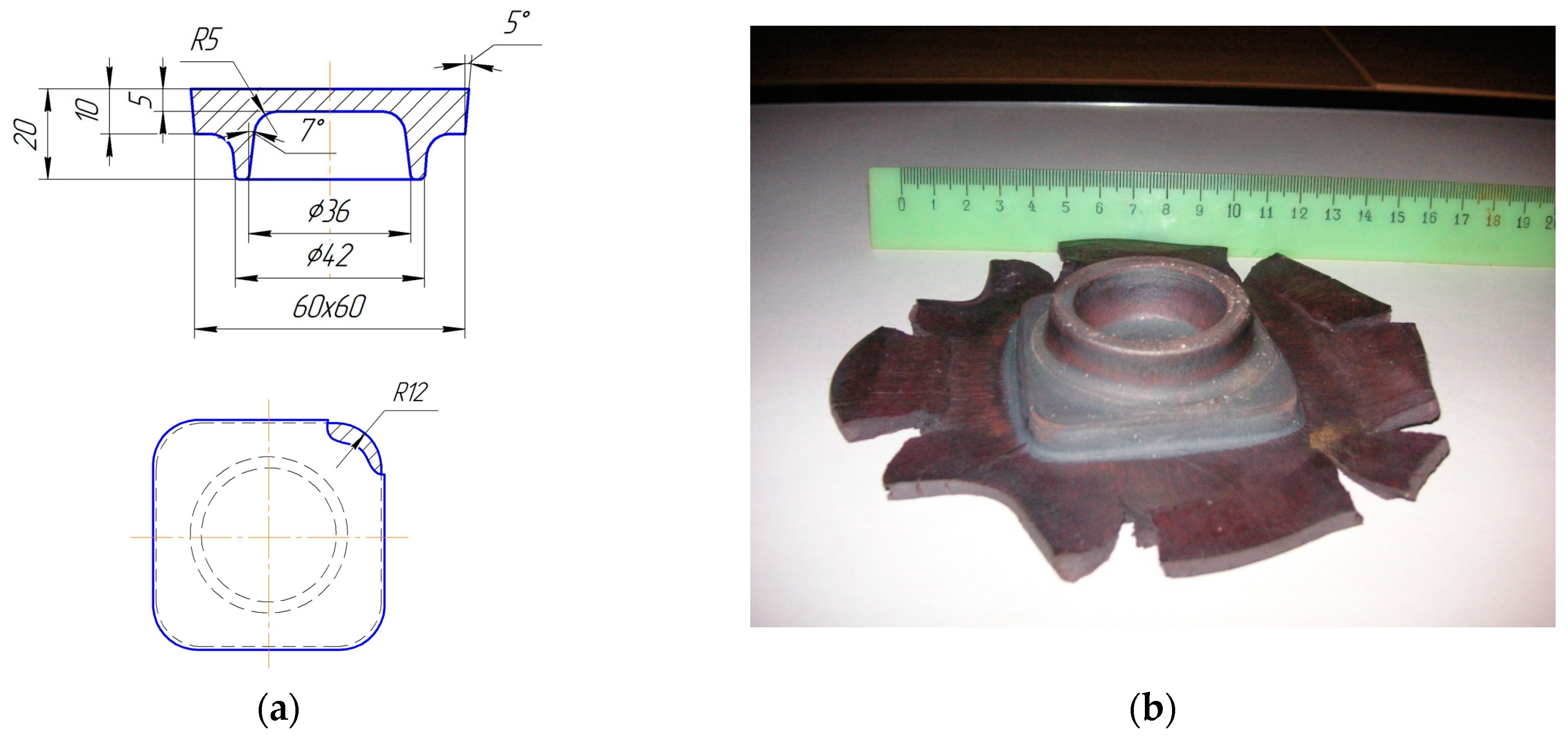
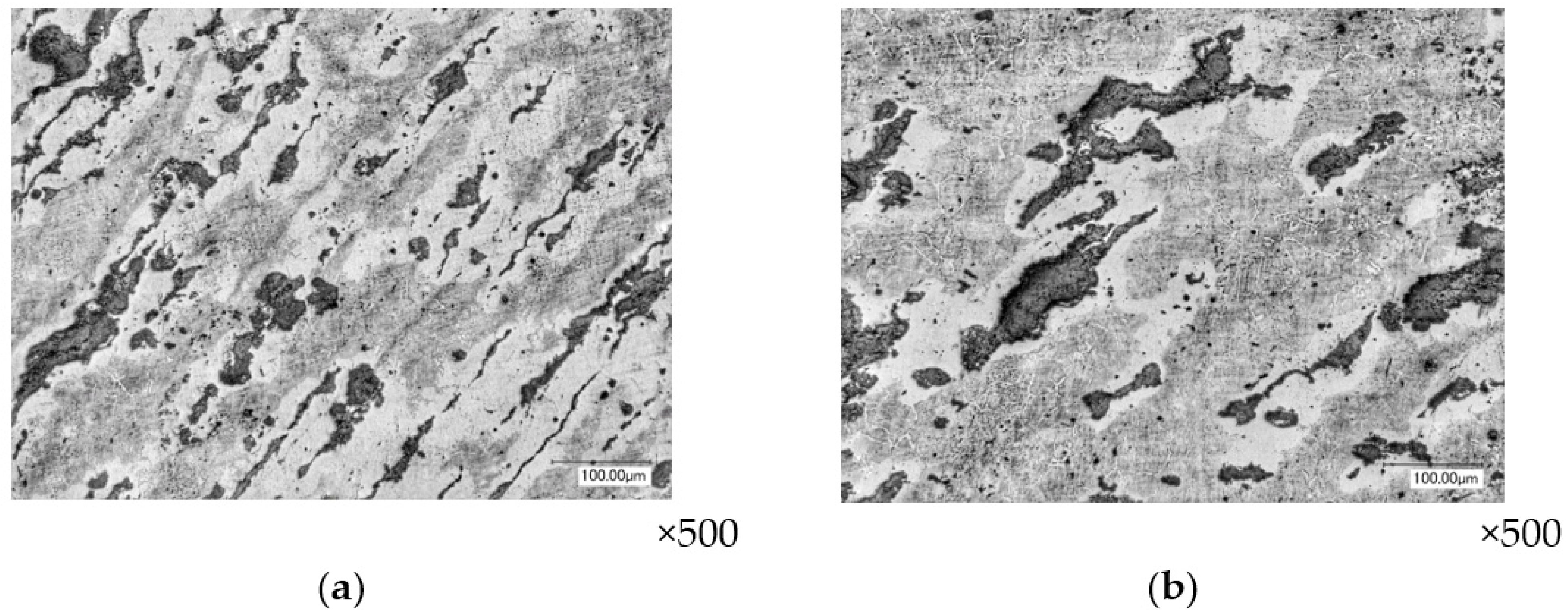
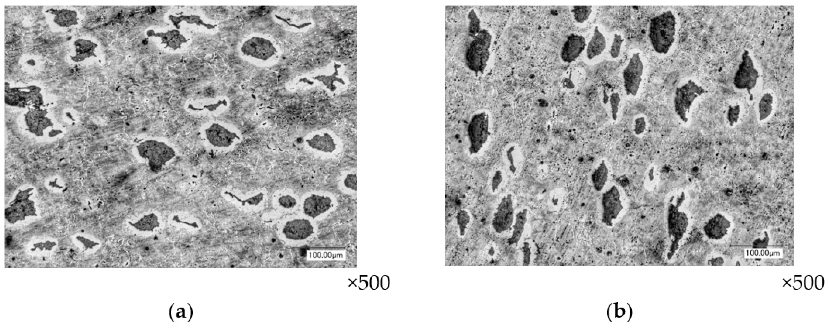
- By the method of hot volumetric stamping in an open die, an experimental batch of forgings of the round shape of the “flange” part, with satisfactory quality of the deformed metal in macro and microstructure, grinding, and orientation of the graphite phase in the direction of the main deformations, was obtained.
- 2.
- The results of the described work made it possible to determine the technological possibility of stamping forgings of round and similar shape in open dies in terms of creating conditions for uneven all-round compression of the material, while cast iron showed plasticity with a value of deformation intensity εi = 2.5.
- 3.
- When stamping in open dies to create conditions for all-round compression, it is rational to use special techniques that simulate hydrostatic pressure, in particular, lateral pressure from the walls of the tool, carried out by selecting the size and shape of the initial workpiece.
- 4.
- The study of structural changes in ductile cast iron during deformation in open dies has shown the ability of graphite inclusions to undergo plastic deformation under conditions of complex loading with changes in shape and size, including their crushing.
Author Contributions
Funding
Institutional Review Board Statement
Informed Consent Statement
Data Availability Statement
Conflicts of Interest
References
- Arzamasov, B.N.; Solovyova, T.V.; Gerasimov, S.A. Handbook of Structural Materials; The Bauman Moscow State Technical University, BMSTU: Moscow, Russia, 2005. [Google Scholar]
- Kiani-Rashid, A.R. and Rounaghi, S.A. The New Methods of Graphite Nodules Detection in Ductile Cast Iron. Mater. Manuf. Process. 2011, 26, 242–248. [Google Scholar] [CrossRef]
- Di Cocco, V.; Iacoviello, F.; Cavallini, M. Damaging micromechanisms characterization of a ferritic ductile cast iron. Eng. Fract. Mech. 2010, 77, 2016–2023. [Google Scholar] [CrossRef]
- Shcherbedinsky, G.V. Iron: A Promising Material of the XXI Century. Met. Sci. Heat Treat. 2005, 47, 333–342. [Google Scholar] [CrossRef]
- Lisovsky, A.V.; Romantsev, B.A. Formation of unique structures and properties for cast iron during hot metal forming. Metallurgist 2010, 54, 173–177. [Google Scholar] [CrossRef]
- Nofal, A.A. Advances in metallurgy and applications of ADI. J. Metall. Eng. 2013, 2, 1–18. [Google Scholar]
- Bell, J.F. Experimental Foundations of Mechanics of Deformable Solids. Part II. Finite Deformations; Nauka: Moscow, Russia, 1984. [Google Scholar]
- Potapova, D.B. Mechanics of Materials in a Complex Stress State; Mechanical Engineering-1: Moscow, Russia, 2005. [Google Scholar]
- Pachla, W.; Mazur, A.; Skiba, J.; Kulczyk, M.; Przybysz, S. Effect of hydrostatic extrusion with back pressure on mechanical properties of grey and nodular cast irons. Arch. Metall. Mater. 2011, 56, 945–953. [Google Scholar] [CrossRef][Green Version]
- Dubinskii, V.N.; Leushin, I.O.; Korovin, V.A.; Galkin, V.V.; Grachev, A.N.; Pryanichnikov, V.A. Hot deformation of cast iron with globular graphite. Steel Transl. 2007, 37, 11–13. [Google Scholar] [CrossRef]
- Pokrovsky, A.D. Hot Plastic Deformation of Cast Iron: Structure, Properties, Technological Bases; Belarusian Science: Minsk, Belarus, 2010.
- Shi, J.; Savas, M.A.; Smith, R.W. Plastic deformation of a model material containing soft spheroidal inclusions: Spheroidal graphite cast iron. J. Mater. Process. Technol. 2003, 133, 297–303. [Google Scholar] [CrossRef]
- Chaus, A.S.; Soyka, J.; Pokrovsky, A.I. The effect of hot plastic deformation on changes in the microstructure of cast iron with spherical graphite. Phys. Met. Metallogr. 2013, 114, 4–104. [Google Scholar] [CrossRef]
- Zhao, X.; Jing, T.F.; Gao, Y.W.; Qiao, G.Y.; Zhou, J.F.; Wang, W. Morphology of graphite in hot compressed nodular iron. J. Mater. Sci. 2004, 39, 6093–6096. [Google Scholar] [CrossRef]
- Dmitriev, E.A.; Sobolev, B.M.; Rybalkin, A.A. Pressure treatment of cast iron with spheroidal graphite. Sci. Notes GTU 2012, 1, 83–86. [Google Scholar]
- Ponomarev, A.S.; Sosenushkin, E.N.; Artes, A.E.; Klimov, V.N. The influence of pressure shaping on microstructure and quality of products from ductile iron. Vestn. Mstu Stank. 2011, 3, 115–120. [Google Scholar]
- Khrol, I.N. The influence of hot plastic deformation on the structure of high–strength cast iron. In Proceedings of the International Symposium “Perspective Materials and Technologies”, Brest, Belarus, 27–31 May 2019. [Google Scholar]
- Qi, K.; Yu, F.; Bai, F.; Yan, Z.; Wang, Z.; Li, T. Research on the hot deformation behavior and graphite morphology of spheroidal graphite cast iron at high strain rate. Mater. Des. 2009, 30, 4511–4515. [Google Scholar] [CrossRef]
- Pokrovsky, A.I. Plastic flow of inclusions of cementite and graphite during pressure treatment of cast iron. Cast. Metall. 2013, 1, 88–95. [Google Scholar]
- Dudetskaya, L.R.; Danilchik, I.K.; Pokrovsky, A.I.; Khrol, I.N. Investigation of the parameters of the foundry-deformation technology for obtaining high-quality cast iron products. Cast. Metall. 2010, 1, 98–109. [Google Scholar]
- Semenov, E.I. Forging and Stamping: Handbook, Volume 2: Hot Volume Stamping; Mashinostroenie: Moscow, Russia, 2010.
- Grechnikov, F.V. Theory of Plastic Deformation of Metals; SNIU n.a. S.P. Korolev: Samara, Russia, 2021. [Google Scholar]


| Content of the Elements, % | |||||||
|---|---|---|---|---|---|---|---|
| C | Si | Mn | Ni | Cr | Mg | S | P |
| 2.60 | 2.15 | 0.60 | 0.38 | 0.14 | 0.07 | 0.019 | 0.09 |
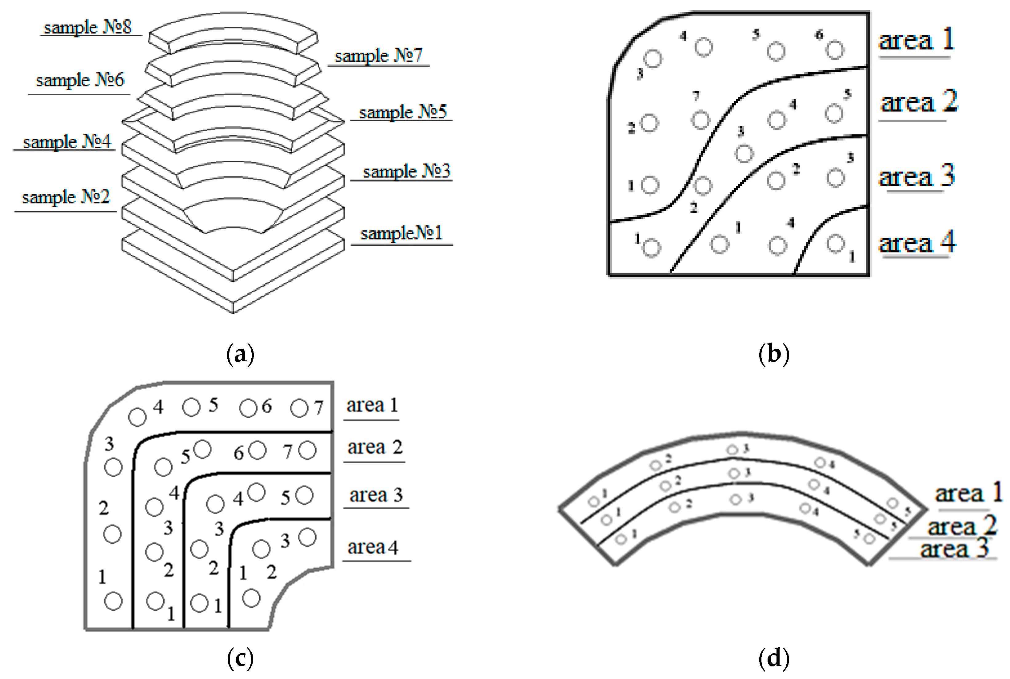
| Sample №1 | Sample №3 | Sample №7 | |||||||||
|---|---|---|---|---|---|---|---|---|---|---|---|
| point | area 1 | area 2 | area 3 | area 4 | area 1 | area 2 | area 3 | area 4 | area 1 | area 2 | area 3 |
| 1 | 2.03 | 2.16 | 1.41 | 1.91 | 0.70 | 1.46 | 1.61 | 2.12 | 2.28 | 1.60 | 1.71 |
| 2 | 2.02 | 1.38 | 1.38 | 0.95 | 1.37 | 1.63 | 1.79 | 2.38 | 1.87 | 2.51 | |
| 3 | 2.43 | 1.28 | 1.60 | 1.00 | 1.50 | 1.64 | 2.21 | 2.38 | 1.54 | 1.57 | |
| 4 | 2.53 | 1.42 | 1.62 | 1.20 | 1.54 | 1.77 | 2.29 | 1.58 | 1.36 | ||
| 5 | 2.26 | 1.45 | 1.22 | 1.58 | 2.28 | 2.02 | 1.59 | 1.63 | |||
| 6 | 2.51 | 1.25 | 1.62 | ||||||||
| 7 | 1.53 | 1.28 | 1.65 | ||||||||
| Sample №1 | Sample №3 | Sample №7 | |||||||||
|---|---|---|---|---|---|---|---|---|---|---|---|
| point | area 1 | area 2 | area 3 | area 4 | area 1 | area 2 | area 3 | area 4 | area 1 | area 2 | area 3 |
| 1 | 239 | 238 | 192 | 189 | 187 | 199 | 195 | 204 | 144 | 143 | 148 |
| 2 | 235 | 194 | 180 | 190 | 203 | 193 | 196 | 144 | 144 | 144 | |
| 3 | 251 | 186 | 188 | 188 | 200 | 189 | 200 | 140 | 145 | 156 | |
| 4 | 255 | 198 | 183 | 197 | 195 | 193 | 145 | 145 | 151 | ||
| 5 | 239 | 199 | 194 | 192 | 199 | ||||||
| 6 | 256 | 197 | 189 | ||||||||
| 7 | 205 | 201 | 195 | ||||||||
Disclaimer/Publisher’s Note: The statements, opinions and data contained in all publications are solely those of the individual author(s) and contributor(s) and not of MDPI and/or the editor(s). MDPI and/or the editor(s) disclaim responsibility for any injury to people or property resulting from any ideas, methods, instructions or products referred to in the content. |
© 2022 by the authors. Licensee MDPI, Basel, Switzerland. This article is an open access article distributed under the terms and conditions of the Creative Commons Attribution (CC BY) license (https://creativecommons.org/licenses/by/4.0/).
Share and Cite
Galkin, V.; Kurkin, A.; Gavrilov, G.; Kulikov, I.; Bazhenov, E. Investigation of the Technological Possibility of Manufacturing Volumetric Shaped Ductile Cast Iron Products in Open Dies. Materials 2023, 16, 274. https://doi.org/10.3390/ma16010274
Galkin V, Kurkin A, Gavrilov G, Kulikov I, Bazhenov E. Investigation of the Technological Possibility of Manufacturing Volumetric Shaped Ductile Cast Iron Products in Open Dies. Materials. 2023; 16(1):274. https://doi.org/10.3390/ma16010274
Chicago/Turabian StyleGalkin, Vladimir, Andrey Kurkin, Gennady Gavrilov, Ilya Kulikov, and Evgeny Bazhenov. 2023. "Investigation of the Technological Possibility of Manufacturing Volumetric Shaped Ductile Cast Iron Products in Open Dies" Materials 16, no. 1: 274. https://doi.org/10.3390/ma16010274
APA StyleGalkin, V., Kurkin, A., Gavrilov, G., Kulikov, I., & Bazhenov, E. (2023). Investigation of the Technological Possibility of Manufacturing Volumetric Shaped Ductile Cast Iron Products in Open Dies. Materials, 16(1), 274. https://doi.org/10.3390/ma16010274