Article

Optimal Design and Competitive Spans of Timber Floor Joists Based on Multi-Parametric MINLP Optimization

Faculty of Civil Engineering, Transportation Engineering and Architecture, University of Maribor, Smetanova ulica 17, 2000 Maribor, Slovenia
*
Author to whom correspondence should be addressed.
Materials 2022, 15(9), 3217; https://doi.org/10.3390/ma15093217
Submission received: 29 March 2022 / Revised: 25 April 2022 / Accepted: 26 April 2022 / Published: 29 April 2022
(This article belongs to the Special Issue Analysis and Design of Structures and Materials)

Abstract

:
This study investigates the optimization of the design of timber floor joists, taking into account the self-manufacturing costs and the discrete sizes of the structure. This non-linear and discrete class of optimization problem was solved with the multi-parametric mixed-integer non-linear programming (MINLP). An MINLP optimization model was developed. In the model, an accurate objective function of the material and labor costs of the structure was subjected to design, strength, vibration and deflection (in)equality constraints, defined according to Eurocode regulations. The optimal design of timber floor joists was investigated for different floor systems, different materials (sawn wood and glulam), different load sharing systems, different vertical imposed loads, different spans, and different alternatives of discrete cross-sections. For the above parameters, 380 individual MINLP optimizations were performed. Based on the results obtained, a recommended optimal design for timber floor joists was developed. Engineers can select from the recommendations the optimal design system for a given imposed load and span of the structure. Economically suitable spans for timber floor joists structures were found. The current knowledge of competitive spans for timber floor joists is extended based on cost optimization and Eurocode standards.

1. Introduction

Timber floor joists consist of parallel timber beams and a structural sheathing, joined together by shear connectors (see Figure 1). Floors made of timber, along with those made of reinforced concrete and steel-concrete composites, are among the most common forms of construction used in the modern building industry [1]. The advantages of timber floors are: use of a natural building material; use of a sustainable building material [2]; low greenhouse gas emissions [3,4]; agreeable interior climate [5]; diverse architectural design options; good ratio between self-weight and load-carrying capacity [6]; fast-dry form of construction; and no scaffolding or props required for erection. Timber floor joists are easily adapted to various levels of loading, fire resistance and sound insulation [7]. This floor system has low self-weight and is highly flexible in terms of fitting out. The disadvantages of floor joists are that considerable structural depth is required and a limited range of solid timber sections is available [8]. The vibration responses of a timber floors have been assessed experimentally [9,10] and numerically [11], and it has been concluded that vibration serviceability of timber floors is increasingly relevant due to their increased long-span applications [12]. With increased floor span, sawn timber beams are replaced with glued laminated timber beams, and secondary timber beams are provided. Based on thermo-mechanical analysis and experimental testing of timber floor systems, design methods for calculating fire resistance have been developed [13].
Nowadays, structural efficiency, economy and environmental behavior are the dominant criteria in the structural design of floor systems [14]. In order to reduce manufacturing costs or mass, various floor structures have often been optimized. While the optimizations of concrete slabs and composite floors have been frequently performed and widely reported, such investigations on timber floors have been very rarely performed according to literature. Among the references in the last five years in the field of structural optimization of concrete slabs is the optimization of large-span prestressed concrete slabs by Kaveh et al. [15] using probabilistic particle swarm, cost optimization of reinforced concrete flat slabs by Aldwaik and Adeli [16] using robust neural dynamics model, design optimization of reinforced concrete slabs by Basha and Latha [17] using the genetic algorithms, optimization of reinforced concrete slab by Stochino and Lopez Gayarre [18] using simulated annealing, the design optimization of reinforced concrete slabs by Suryavanshi and Akhtar [19] using various metaheuristic optimization algorithms, the optimization of reinforced concrete slabs according to Eurocode 2-EC2 by Fedghouche [20] using the generalized reduced gradient algorithm, the cost optimization of reinforced concrete slabs by Sedaghat Shayegan et al. [21] using the mouth brooding fish algorithm and the optimization of a reinforced concrete ribbed slab by Imran et al. [22] using the genetic algorithm.
Concrete-steel composite floor structures have also been optimized. In the last decade, Kaveh and Shakouri Mahmud Abadi [23] presented the cost optimization of a composite floor using the improved harmony search algorithm, while Omkar et al. [24] presented the multi-objective design optimization of composite structures using the artificial bee colony algorithm. Poitras et al. [25] reported the optimization of composite and steel floor systems using particle swarm optimization. Kaveh and Behnam [26] performed the cost optimization of a composite floor, waffle slab and concrete slab formwork using the charged system search algorithm, while Kaveh and Ahangaran [27] introduced the discrete cost optimization of a composite floor using the social harmony search model. Luo et al. [28] presented an optimal topology design of composite structures using a standard gradient-based search. Žula et al. [29] and Kravanja et al. [30] performed the optimization of a composite floor system using mixed-integer non-linear programming, and Silva and Rodrigues [31] carried out the optimization of steel-concrete composite beams using sequential linear programming. In addition, Jelušič and Kravanja [32] reported the cost optimization of timber-concrete composite floors using multi-parametric mixed-integer non-linear programming, while Kaveh and Ghafari [33] optimized a steel floor system using enhanced colliding body optimization.
In the field of timber floor structures, Stanić et al. [34] and Brank et al. [35] optimized the cross laminated timber plates with ribs. They performed cost optimization of floors using a gradient-based algorithm for mechanical systems by Kegl and Butinar [36]. Mayencourt et al. [37] and Mayencourt and Mueller [38] studied the structural optimization of cross-laminated timber panels. They performed material consumption optimization of structures using the non-linear programming solver (fmincon), implemented in Matlab. Santos et al. [39] applied the cost optimization of cross-insulated timber panels. They also used Matlab software (fmincon solver). Finally, Nesheim et al. [40] reported the cost and ECO2 optimization of timber floor elements for adaptable buildings. For the optimization, they used the mixed-integer sequential linearization procedure.
The above references of timber floor structures do not indicate spans for which timber floor systems are economically viable. There is some information in the literature on the competitive spans of timber floors based on the classical calculations from engineering practice. Kolbitsch [41] reported that a timber floor system with timber beams and sheathing is suitable for spans ranging from 2 to 7 m. While Kolb [42] showed that this system is suitable for spans between 4 and 7.5 m, Cobb [43] proposed this floor system for spans between 1 and 6.5 m. For longer spans, PINE Manufacturers [44] showed that timber floors with glued beams are suitable for spans from 2 to 10 m, while APA [45] reported suitable spans of floors with glued beams from 2.44 m to 15.85 m.

2. Materials and Methods

2.1. Objectives and Framework of the Study

The novelty of this work is not only the calculation of the optimal design, but also the determination of the competitive spans of timber floor joists, based on the optimization performed and the Eurocode specifications. In contrast to the above-mentioned references in the field of timber floors, which reported individual cost/design optimizations of structures, this work deals with a multi-parametric cost optimization performed for different spans, loads and systems.
With this study, we aimed to verify the above-mentioned spans of timber floor joists and also to increase the knowledge about these spans based on cost optimization and Eurocode standards. In the paper, we propose to determine the competitive spans of two different timber floor systems (see Figure 1):
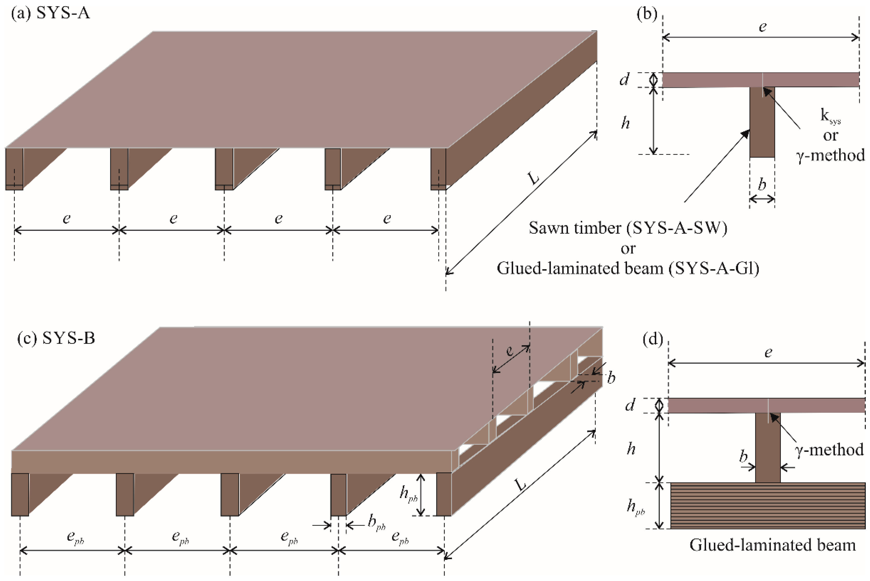
  • Floor system A (SYS-A), which contains only timber beams and structural sheathing. However, two types of timber beams are used in SYS-A:
    Sawn wood (SYS-A-SW) and
    Glued laminated timber (SYS-A-Gl);
  • Floor system B (SYS-B) made of glued laminated primary timber beams, sawn secondary timber beams and structural sheathing as the main components.
The cost optimizations of the timber floor structures were calculated using mixed-integer non-linear programming (MINLP). MINLP enables simultaneous continuous and discrete optimization. For this purpose, continuous and discrete binary 0–1 variables are defined. The continuous variables are used for optimization of sizes, inner forces, deflections, costs and mass, whilst the discrete variables are employed to calculate material grades and standard sizes. A Modified Outer-Approximation/Equality-Relaxation (OA/ER) algorithm was used to perform optimization of the discrete and non-linear class of the timber floor structure; see Kravanja and Grossmann [46] and Kravanja et al. [47].
We developed an MINLP model for the optimization of timber floor joists in which an objective function of the structure’s self-manufacturing costs is subjected to design, resistance, vibration and deflection constraints. These dimensioning constraints satisfy the conditions of ultimate and serviceability limit states according to Eurocode regulations [48]. Optimal design of the timber floor joists was studied for different important design parameters, such as different floor systems, spans, vertical imposed loads, timber strengths and discrete dimensions of cross-sections. Since a number of individual MINLP optimizations were calculated for the different defined parameters, a multi-parametric MINLP optimization of the floor structure was performed.
Based on the results obtained, a recommended optimal design for timber floor joists was developed. A sensitivity analysis was performed on the contribution of various design parameters to the variability of the overall production costs of timber floor systems, and economically suitable timber floor systems for various spans were found. Finally, competitive spans were determined for the considered timber floor joists.

2.2. MINLP Optimization Model

In order to perform a cost optimization of timber floor joists, an MINLP optimization model titled TIMBFJ (TIMBer Floor Joists) was developed. It was modelled in the GAMS environment (General Algebraic Modeling System, commercial software) [49], and it enables the MINLP optimization of a structure for different design parameters such as different loads, spans, strengths and prices. The following assumptions were applied in the optimization model and the calculation:
  • two different floor systems were considered:
    timber floor with primary beams (SYS-A),
    timber floor system with primary and secondary beams (SYS-B);
  • two different sharing systems for mechanically jointed timber floors were used:
    system strength factor ksys,
    Gamma method;
  • depths (heights) of the beams were bounded to be less than or equal to the extreme values which are still, but very rarely, used in the practice:
    30 cm for sawn wood beams,
    150 cm for glued laminated timber beams;
  • Eurocode 5 was used to define the dimensioning constraints;
  • prices in Central Europe were considered in the study.
The diversity of different structure systems and joint treatments described above enables us to make an economical comparison between sawn (SYS-A-SW) and glued (SYS-A-Gl) laminated timber beams.

2.2.1. MINLP Model Formulation

The proposed cost and discrete sizing optimization of a timber floor structure is a combined continuous, discrete and non-linear type of optimization. The optimization model is modelled on the following MINLP formulation:
min z = f(x,y),
subjected to:  gk (x,y) ≤ 0   kK
xX = {xRn: xLOxxUP}
yY = {0,1}m
MINLP handles continuous variables x and discrete (binary) variables y. Continuous variables are used here to determine the structure costs, loads, loadings, resistances and deflections, while discrete binary variables are employed for choosing the discrete sizes of timber cross-sections. The cost objective function z is subject to the design, loading, stress, resistance and deflection (in)equality constraints, gk (x,y) ≤ 0, kK. These constraints represent the calculation of inner forces and the dimensions of the structure, where the ultimate and serviceability limit state conditions are defined according to Eurocode standards.
The proposed TIMBFJ optimization model includes input data (constants), variables, sets, parameters, the cost objective function of the structure, structural analysis and dimensioning constraints, and logical constraints. The main input data, continuous and discrete variables, sets and parameters are listed in Table 1. While the main input data include a structure span L (m), an imposed load qk (kN/m2), various material properties, factors and prices, the continuous variables include the production costs of the structure COST, dimensions, cross-section characteristics, stresses, deflections, masses, etc. Sets, discrete variables and parameters are defined to calculate/select the discrete/standard materials (characteristic bending strength of timber) and standard dimensions.

2.2.2. Cost Objective Function

For two different floor systems, SYS-A and SYS-B, the objective function of the self-manufacturing costs COST (EUR/m2) of timber floor joists is defined by Equation (1):
min :   C O S T S Y S - A = C M , t + C M , i m p + C M , b o a r d + C L , b o a r d min :   C O S T S Y S - B = C M , t + C M , i m p + C M , b o a r d + C L , b o a r d + C M , t , p b + C M , i m p , p b .
Different cost items of the objective function for systems SYS-A and SYS-B are presented in Table 2. While floor system SYS-A includes only cost items defined by Equations (2)–(5), system SYS-B also includes items for glulam primary beams determined by Equations (6) and (7). This study considered the cost of spruce wood (Picea Excelsa), one of the most commonly used materials in the construction industry.
In Equations (2)–(7), cM,t (€/m3) is the unit price of the timber, cM,imp (€/m3) is the unit price of timber impregnation, cM,board (€/m2) is the unit price of the prefabricated floor boards and cL,board (€/m3) is the unit price of floor board placing. Index pb is used to define the dimensions of the glulam primary beam in system SYS-B; see Equations (6) and (7).
On local markets, the unit prices of floor boards depend on their thicknesses. Floor boards with higher thickness are generally more expensive. The unit price of prefabricated timber boards cM,board = f(d) is thus included in the cost objective function by applying an approximation function which was formulated by executing multiple regression using MS Excel software with Data Analysis Add-in. The price per unit of timber floor board cM,board (€/m2) is thus calculated to be dependent on the thickness; see Equation (8), where cboard (€/m2) stands for the basic price per unit of timber board; the thickness of timber board d must be defined in mm.
c M , b o a r d = c b o a r d · ( 0.0762 · d + 0.5238 ) .

2.2.3. Structural Analysis and Dimensioning Constraints

The cost objective function is subjected to structural analysis and dimensioning constraints which are defined in accordance with Eurocode standards [50]; see Equations (9)–(58). Equations (10)–(43) in Table 3 stand for the floor system SYS-A (and for the secondary beams and floor boards of the system SYS B), and Equations (44)–(58) in Table 4 are defined for the glulam primary beams of the floor system SYS-B. In this paper only the most important equations are presented. For a better understanding of the symbols (constants and variables) used in the equations; see Table 1. The timber structure is dimensioned to support its own weight gk (kN/m2, timber beams plus floor boards) and the uniformly distributed variable imposed load qk (kN/m2); see Equation (9):
γ g   ·   g k + γ q   ·   q k .
Partial factors for actions γg =1.35 and γq =1.5 are defined at the ultimate limit state and γg = 1.0 and γq = 1.0 at the serviceability limit state.
The ultimate limit state condition, where the maximal design bending stress in timber beam σm,y,d (MPa) must not exceed the design bending strength of the timber fm,y,d (MPa) is calculated by Equation (10). In Equations (11)–(14), the design bending strength is calculated by using a loading sharing factor ksys. In the equations, kh is a depth factor, kmod is a modification factor for duration of load and moisture content, fmk is the characteristic bending strength of timber, γk is the specific weight of timber, γboard is the specific weight of timber boards and γM is a partial factor for material properties. The design bending stress in the above equation is calculated without considering the favorable action of timber boards. Therefore, the Gamma method is also proposed to calculate the effective stiffness of the timber floor system (EI)eff, see Equations (15)–(23). In the equations, E and Eboard are the modules of elasticity of timber and timber boards, respectively, and γ1 and γ2 determine the composite action of the beam and timber board. Equations (17)–(23) define substituted terms Ic,eff, Ac,eff, ad,c,eff, ad,tim and Itim involved in (EI)eff. Constraint Equation (24) determines that the calculated maximal design shear stress in timber beams τmax (the stress component perpendicular to the grain, MPa) must not exceed the design shear strength of the timber fvd (MPa). τmax and fvd are defined by Equations (25) and (26), respectively, where fvk (MPa) stands for the shear strength of the timber beam. In the design methodology according to the Gamma method, the maximal design shear stress is expressed by Equation (27).
Equation (28) define the conditions under which the maximal design bending stress in timber board σboard,y,d (MPa) must not exceed the design bending strength in board fboard,y,d (MPa). σboard,y,d and fboard,y,d are defined according to Equations (29)–(32). In the equations, gk,board represents the self-weight (kN/m2) of the floor board, depth factor kh,board is taken to be equal to 1.3 because of the small thickness of the board and fboard,y,k (MPa) represents the characteristic bending strength of timber board. In addition, Equation (33) defines that the maximal design shear stress in the board τboard,max (the stress component perpendicular to the grain, MPa) must not exceed the design shear strength in the board fboard,vd (MPa). τboard,max and fboard,vd are determined by Equations (34) and (35), respectively, where fboard,vk (MPa) represents the characteristic shear strength of timber board.
The serviceability limit state condition, where the instantaneous deflection of the timber beam uinst (m) must be less than or equal to the recommended value, is defined by Equation (36). In the case when the system strength factor ksys is used, uinst is defined by Equation (37). In the case of the Gamma method design, the instantaneous deflection of the timber beam is expressed by Equation (38). The instantaneous deflection of the timber boards uinst,board (m) must also be less than or equal to the allowable value; see Equation (39). Deflection uinst,board is expressed by Equation (40). The calculated final deflection of the timber beam ufin (m) must be less than or equal to the recommended value; see Equation (41). In the case of using the factor ksys, ufin is defined by Equation (42), where ψ2 is the factor for the quasi-permanent value of the variable action and kdef is the deformation factor. In this way, the deflection of the structure resulting from the effect of long-term use and moisture is limited. The final deflection ufin, calculated by the Gamma method, is determined by Equation (43). The final deflection of the timber board ufin,board (m), which must be less than the recommended value, is verified by Equation (44). The substituted final deflection ufin,board is expressed by Equation (45).
The constraint Equation (46) defines that the proportion of the point load acting on a single joist kdist must be greater than or equal to the acceptable value. kdist is expressed by Equations (47) and (48), where EIb (Nm2/m) is the equivalent board/plate bending stiffness parallel to the beams and kstrut stands for the partial factor for the installed strutting. Equation (49) defines the condition, where the vertical deflection w (m) of the joist caused by the concentrated static force F = 1.0 kN must not exceed the allowable deflection a (m). Terms w and a are expressed by Equations (50)–(52), where kamp is the amplification factor that takes into account the shear deflection, and (EI)joist is the stiffness of the joist, which in the case of the Gamma method used is equal to the effective stiffness of the timber floor system (EI)eff, Equation (53).
According to Equations (54)–(56), the fundamental frequency of vibration of a rectangular residential floor f1 (Hz) should exceed 8 Hz, where EIl (Nm2/m) is the equivalent bending stiffness of the joists divided by the joist spacing in the beam direction and massv (kg/m1) is the mass of the timber floor structure. Finally, the calculated unit impulse floor velocity ν (1/Ns) must be less than or equal to the allowable floor velocity νallow (1/Ns); see Equations (57)–(62), where n40 represents the number of first-order modes with natural frequencies less than 40 Hz, bfloor (m) represents the floor width, bvr denotes the velocity response value, ξ is the modal damping coefficient, and the other symbols are defined as above.
The above equations are used for the floor system SYS-A and for the upper part of the floor system SYS-B (for the secondary beams and timber boards of the system SYS-B). Equations (63)–(82) are defined for the calculation of the primary glulam beams of the system SYS-B. These equations are nearly identical to those of the system SYS-A, so the terms in the equations are indexed pb (primary beam). Equations (63)–(67) define that the design bending stress in the primary beam σm,y,d,pb (MPa) must not exceed the design bending strength of the timber of the primary beam fm,y,d,pb (MPa), Equations (68)–(70) define that the design shear stress in the primary beam τmax,pb (MPa) must not exceed the design shear strength of the timber of the primary beam fvd,pb (MPa), Equations (71) and (72) define that the instantaneous deflection of the primary beam uinst,pb (m) must be less than or equal to the recommended value, Equations (73) and (74) calculate that the final deflection of the primary beam ufin,pb (m) must be less than or equal to the recommended value, Equations (75)–(76) regulate that the proportion of the point load acting on a single primary beam kdist,pb must be greater than or equal to the acceptable value, and Equations (77)–(79) limit the vertical deflection of the primary beam wpb (m) caused by the concentrated static force F = 1.0 kN.
Structural analysis and dimensioning (in)equality constraints also determine the timber floor joist dimensions and the material properties to be calculated inside the defined limits. The characteristic shear strength of the timber beams fvk (MPa), the specific weight of the timber beams γk (kN/m3) and the modulus of elasticity of the timber E (MPa) are substituted in the optimization model as functions of the characteristic bending strength of timber fmk (MPa); see Equations (80)–(82).
f v k = 0.4311 + 0.0858 · f m k
γ k = 2.3 + 0.05 · f m k
E = 3714.3 + 970.24 · f m k 14.881 · f m k 2 .
The glued laminated timber beams are usually manufactured with a height to width ratio smaller than or equal to 12, see Equation (83).
h b 12 .

2.2.4. Logical Constraints

The objective function is subject to logical constraints which determine the discrete values for dimensions of cross-sections and the discrete values for standard materials (strengths). Each discrete dimension dst (or timber strength) is defined as a scalar product between the vector of j, j J , discrete dimension alternatives qj = {q1, q2, q3,, qj}, and the vector of j associated binary variables yjst = {y1st, y2st, y3st,…, yjst}; see Equation (84). Only one discrete value is selected for the dimension since the sum of the binary variables yjst has to be equal to 1; see Equation (85).
d s t = j J q j y j s t
j J y j s t = 1 .
Figure 2 shows the flowchart of the optimal design of timber floor joists based on multi-parametric MINLP optimization.

2.3. Multi-Parametric MINLP Optimization

Multi-parametric MINLP optimization of the production costs of the timber floor joists was performed for combinations of different design parameters:
  • Nineteen different structure spans: 2 m, 3 m, 4 m, 5 m, 6 m, 7 m, 8 m, 9 m, 10 m, 11 m, 12 m, 13 m, 14 m, 15 m, 16 m, 17 m, 18 m 19 m and 20 m;
  • Five different imposed loads: 1 kN/m2, 2 kN/m2, 3 kN/m2, 4 kN/m2 and 5 kN/m2;
  • For this purpose, 95 individual MINLP optimizations were executed. For each combination, two different load sharing systems were applied:
  • The system strength factor ksys;
  • The Gamma method.
In the structural analysis, the following values were assigned: ksys = 1.1 and γ1 = 0.2. By assigning a corresponding value γ1, different types of fastening can be used for the sheathing. The sheathing can be fastened with nails or screws at the appropriate distances as long as the gamma value γ1 is guaranteed. The gamma factors γ1 in case the sheathing is fastened with screws or nails can be calculated with the following equations:
γ 1 = ( 1 + π 2 · E · A · s i K i · L 2 ) 1
K i = ρ m 1.5 · 23 ;   for   screws
K i = ρ m 1.5 · 23 ;   for   nails   ( without   pre - drilling ) ,
where Ki is the slip modulus, ρm is the mean wood density, ϕ is the diameter of the fastener, si is the spacing between the fasteners, L is the span, and A is the cross-sectional area of the sheathing.
Numbers of different discrete alternatives for dimensions of cross-sections and beam spacings were defined; see Table 5. These dimensions (available on the market) were discretized in order to obtain real structural solutions. Only the characteristic bending strength fmk = 24 MPa is defined in the model because most companies provide just this timber strength. The combinatorics of the defined discrete alternatives in the SYS-A floor system yielded daltern × baltern × haltern × ealtern × fmk,altern = 3 × 16 × 12 × 12 × 1 = 6912 different structure alternatives (for each different combination between the defined imposed load and structure span). In the SYS-B floor system with primary and secondary timber beams, the number of combinations between different discrete alternatives increased to daltern × baltern × haltern × ealtern × fmk,altern × bpb,altern× hpb,altern× epb,altern= 3 × 16 × 12 × 13 × 1 × 12 × 61 × 31 = 169,917,696 different structure alternatives. Only one is optimal (for a given load and span).
The MINLP optimization model TIMBFJ was used. The task of the optimizations was to calculate the minimal self-manufacturing costs of the timber floor joist (€/m2), the structure mass (kg/m2) and all the dimensions (design variables). The material unit prices (December 2021), labor costs and other data are shown in Table 6. Values from engineering practice in Central Europe were adopted.
The Modified Outer-Approximation/Equality-Relaxation (OA/ER) algorithm by Kravanja and Grossmann [46] and a two-phase MINLP strategy [47] were used. The OA/ER optimization algorithm solves an alternative sequence of non-linear programming (NLP) sub-problems and mixed-integer linear programming (MILP) master problems. The NLP corresponds to the continuous optimization of parameters and yields an upper bound towards the objective to be minimized. The MILP involves a global linear approximation to the superstructure of discrete alternatives in which new discrete sizes are identified. The optimization search is terminated when the predicted lower bound exceeds the upper bound. In cases of non-convex problems, the optimization process is terminated when the NLP solution can no longer be improved. The OA/ER algorithm guarantees global optimality of solutions for convex and quasi-convex optimization problems. The optimization is proposed to be performed sequentially in two different phases in order to accelerate the convergence of the OA/ER algorithm:
  • The optimization is proposed to start with continuous NLP optimization of the structure (the initialization), where all variables are treated as continuous. The result represents a good starting point and accumulates an effective global linear approximation of the superstructure for the next discrete optimization;
  • The optimization continues with MINLP discrete optimization (a sequence of NLP and MILP solutions) in the second phase until the optimal solution is found.
The optimizations were carried out by the MINLP computer package MIPSYN [50,51]. While GAMS/CONOPT (generalized reduced-gradient method, commercial software) by Drudd [52] was used to solve the NLP sub-problems, GAMS/CPLEX (branch and bound method, commercial software) [53] was employed to find solutions to the MILP master problems.

3. Results and Discussion

3.1. Recommended Optimal Design for Timber Floor Joists

The recommended optimal design for timber floor joists was determined on the basis of multi-parametric MINLP optimization; see Table 7, Table 8 and Table 9. The recommended design is shown depending on different variable imposed loads qk and different structure spans L.
Comparative analysis of the results shows that it is more economical to increase the timber beam height than to reduce the spacing between beams. If the Gamma method (γ1 = 0.2) is used instead of the strength system factor (ksys = 1.1), the costs can be reduced by up to 10%.
Among all the defined conditions relating to timber boards, the serviceability limit state was found to be decisive. This finding applies to all optimal designs of timber floors. The condition of the vertical deflection caused by a concentrated static force F = 1.0 kN is decisive for small loads up to 2 kN/m2 for all considered spans and all timber floor systems (SYS-A-SW, SYS-A-Gl and SYS-B). In the SYS-A-SW system with spans ranging up to 4 m and for imposed loads larger than 2 kN/m2, the main difference between the strength system factor (ksys) method and the Gamma method (γ) is:
  • If the strength system factor (ksys) is used, the critical condition is the bending strength of the timbe;
  • While if the Gamma method is used, the critical condition is the final deflection of the timber floor.
In the SYS-A-Gl system, the bending strength of timber was found to be decisive for imposed loads larger than 3 kN/m2 for all considered spans. In the SYS-B system, for spans longer than 5 m and imposed loads larger than 2 kN/m2, the ultimate limit state is dominant for primary glued lamented timber beams, while the serviceability limit state is dominant for secondary sawn timber beams.

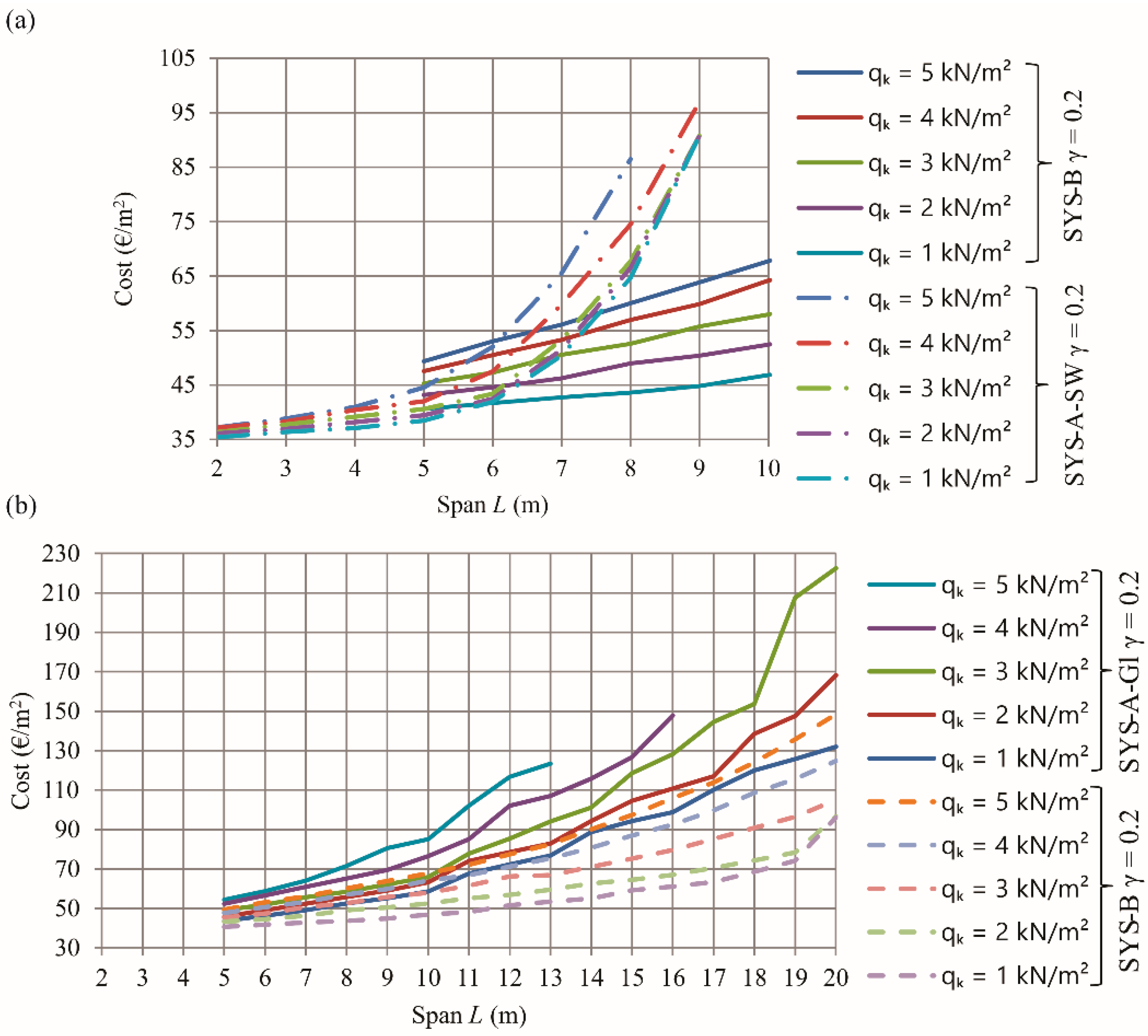
3.2. Economically Suitable Spans of Timber Floor Joists

Figure 3 shows diagrams of the calculated optimal self-manufacturing structure costs of nine different spans ranging from 2 m to 10 m. The diagrams were developed for five different variable imposed loads from 1 kN/m2 to 5 kN/m2, and clearly show that floor joists made of SYS-A-SW sawn timber beams are economically suitable for spans up to 6 m. For these spans, SYS-A-SW is the most appropriate system for all imposed loads. It should be noted that for imposed loads from 1 kN/m2 to 3 kN/m2 and spans longer than 8 m, nearly the same optimal solutions were calculated, because of the decisive vibration velocity condition.
Figure 4a presents diagrams of the calculated optimal self-manufacturing structure costs of the SYS-A-SW (primary sawn timber beams only) floor system and of the SYS-B (with primary glulam beams and secondary sawn timber beams) floor system. The diagrams are drawn for different spans (from 2 m to 10 m) and for different imposed loads (from 1 kN/m2 to 5 kN/m2). A comparison between the diagrams clearly shows that the SYS-B system is more economically suitable than the SYS-A-SW system for spans longer than 6 m.
Figure 4b presents diagrams of the calculated optimal self-manufacturing structure costs of the SYS-A-Gl timber floor system (primary glued laminated beams only) and of the SYS-B floor system. For all defined loads, the SYS-A-Gl system is economically suitable for spans up to 10 m, while the SYS-B system is economically suitable for spans up to 20 m. The SYS-B system is more appropriate than SYS-A-Gl for all defined loads and spans.

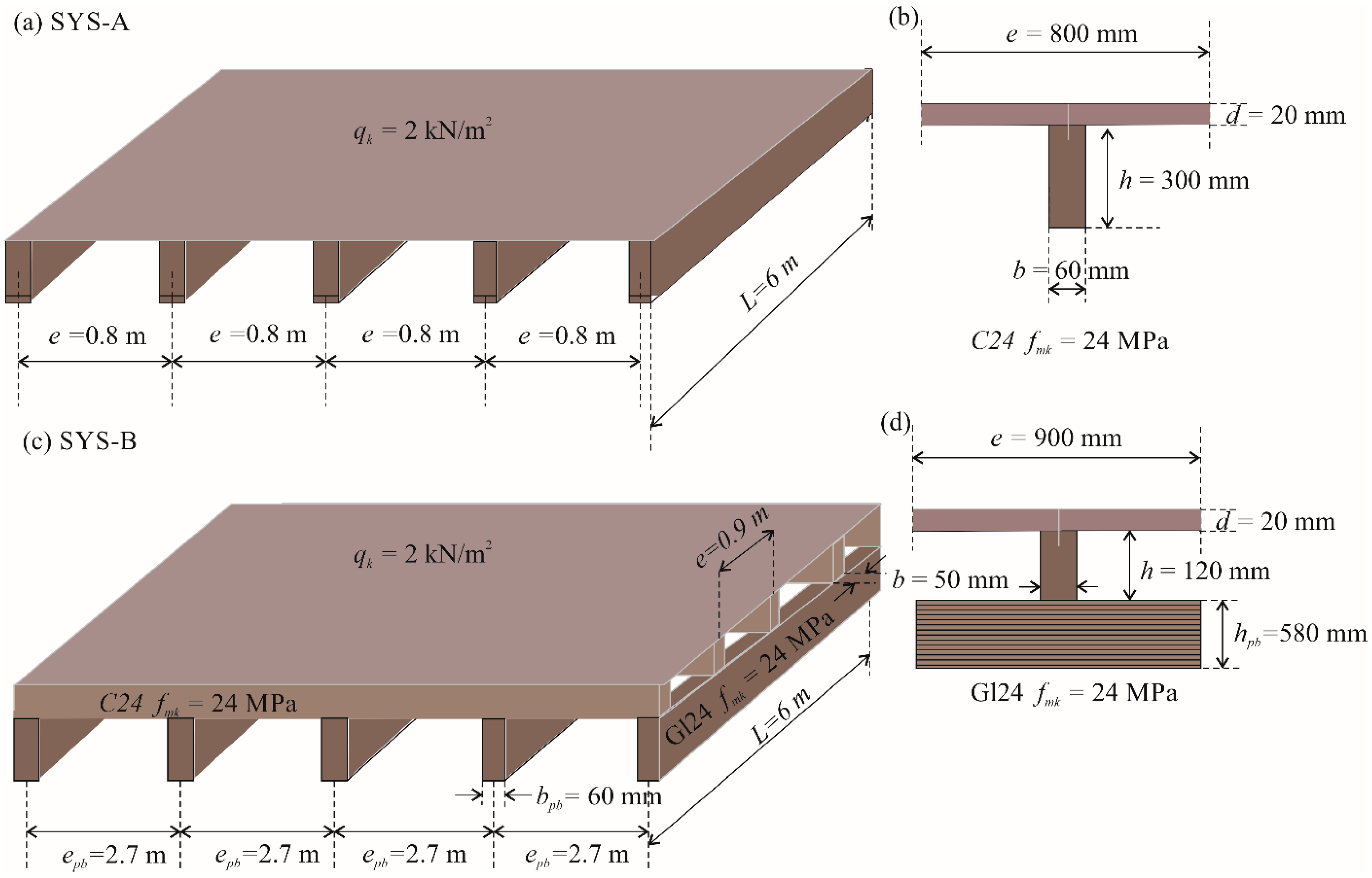
3.3. Calculation Example

In order to interpret the applicability of the comparative diagrams and the recommended optimal design for the timber floor joists, we present a calculation example that determines the most favorable joist structure for the given design parameters and two different load cases.

3.3.1. The structure Self-Weight

In this example, we determine the most competitive design for timber floor joists with a span of L = 6 m, subjected to the structure self-weight and the vertical variable imposed load of qk = 2 kN/m2. It should be noted that the Gamma method (γ1 = 0.2) is applied.
Figure 3b shows that the optimal timber floor SYS-A-SW with a span of 6 m and a vertical imposed load of 2 kN/m2 yields self-manufacturing costs of about 42 €/m2. The recommended floor joists in Table 7 for a span of 6 m and imposed load of 2 kN/m2 are comprised of: thickness of the floor board d = 20 mm, width of the timber beam b = 60 mm, height of the beam h = 300 mm, spacing between floor beams e = 0.8 m, characteristic bending strength of timber fmk = 24 MPa, mass of the structure mass = 17.88 kg/m2 and self-manufacturing costs of the structure COST = 42.44 €/m2. The optimal design is shown in Figure 5a. For system SYS-B, Figure 4 shows optimal manufacturing costs for the given design parameter at less than 45 €/m2. The recommended design for system SYS-B in Table 9 is comprised of: thickness of the floor board d = 20 mm; width of the secondary timber beam b = 50 mm; height of the secondary beam h = 120 mm; spacing between secondary floor beams e = 0.9 m; characteristic bending strength of timber fmk = 24 MPa; width of the primary glulam beam bpb = 60 mm; height of the primary glulam beam hpb = 580 mm; spacing between primary beams epb = 2.7 m; mass of the structure mass = 16.8 kg/m2 and self-manufacturing costs of the structure COST = 44.6 €/m2; see Figure 5.

3.3.2. The Structure Self-Weight Plus Additional Permanent Load

In the same example (timber floor joists with a span of L = 6 m, subjected to the structure self-weight and a vertical variable imposed load of qo = 2 kN/m2), the load on the floor is added, which includes the floor finishing 0.50 kN/m2, the insulation between the beams 0.10 kN/m2 and the ceiling under the beams 0.30 kN/m2, which together gives 0.90 kN/m2 of additional permanent load gp.
Since the comparative diagrams and recommendations are shown in dependence on the vertical imposed load only, the additional permanent load gp of 0.90 kN/m2 must be transformed into a variable load and added to the defined variable imposed load qo = 2 kN/m2. Taking into account Equation (9) and different partial factors for actions at the ultimate limit state for permanent and variable loads, the defined variable imposed load of 2 kN/m2 can be modified with the additional permanent load gp by Equation (89):
q k = q 0 + g p · γ g γ q = 2.0 + 0.9 1.35 1.5 = 2.81   kN / m 2 .
The nearest upper integer value to the calculated modified imposed load qk is 3 kN/m2. Comparing the self-manufacturing costs plotted in Figure 3 and Figure 4 for a span of 6 m and a vertical imposed load of 3 kN/m2, the diagram in Figure 3b shows that the cheapest timber floor system is SYS-A-SW at about 44 €/m2. The recommended timber structure from Table 7 includes the thickness of floor boards of 20 mm, timber beam width of 50 mm, beam height of 300 mm, beam spacing of 0.6 m, characteristic bending strength of timber 24 MPa, structure mass 18.75 kg/m2 and self-manufacturing structure costs of 43.38 €/m2, see Figure 6.

4. Conclusions

The optimization of timber floor joists takes into account the minimal self-manufacturing costs of a timber structure and the discrete sizes of each element’s cross-sections. Because the optimization problem is discrete and non-linear, mixed-integer non-linear programming (MINLP) was applied to develop the TIMBFJ optimization model, in which an accurate objective function of the structure’s material and labor costs is subjected to design and dimensioning (in)equality constraints, which were defined in accordance with the requirements of Eurocode standards. Two different structural floor systems were considered: a system which contains only timber beams and sheathing, and a system with primary and secondary beams and sheathing (the secondary beams are laid on the primary ones). Two different load sharing systems were applied, a load sharing factor and a system using the Gamma method. Two different materials were used, sawn wood and glued laminated timber. A number of individual MINLP optimizations were calculated for different timber floor systems, vertical imposed loads, spans and alternatives of discrete cross-sections, and a multi-parametric MINLP optimization of the timber floor joists was performed. The optimization problems were solved using the Modified Outer-Approximation/Equality-Relaxation (OA/ER) algorithm and the MINLP computer package MIPSYN.
A comparative analysis of the calculated results shows that it is more economical to increase the timber beam height than to reduce the spacing between beams. If the Gamma method (γ1 = 0.2) is used instead of the strength system factor (ksys = 1.1), costs can be reduced by up to 10%. On the basis of the obtained results, a recommended optimal design for timber floor joists was developed. Using these recommendations, an engineer can choose the optimal structure system and material (sawn wood or glulam) for a defined vertical variable imposed load and structure span.
It was found that floor joists made of primary sawn timber beams only (SYS-A-SW) are economically suitable for spans up to 6 m for all defined imposed loads (up to 5 kN/m2). This system is the most appropriate floor system for shorter spans. For spans longer than 6 m, a floor system constructed of primary glulam beams and secondary sawn timber beams (SYS-B) is more economically suitable.
For imposed loads up to 5 kN/m2, a floor system consisting of primary glulam beams only (SYS-A-Gl) is economically suitable for spans up to 10 m, while a floor system constructed of primary glulam beams and secondary sawn timber beams (SYS-B) is economically suitable for spans up to 20 m. A floor system consisting of primary and secondary beams (SYS-B) is more appropriate than a system consisting of primary glulam beams only (SYS-A-Gl) for all the loads and spans studied. In this way, the competitive spans of the considered timber floor joists were found based on the cost optimization.

Author Contributions

Conceptualization, P.J. and S.K.; methodology, S.K.; software, P.J.; validation, P.J. and S.K.; writing—original draft preparation, P.J.; writing—review and editing, S.K. All authors have read and agreed to the published version of the manuscript.

Funding

This research was funded by Slovenian Research Agency, grant numbers P2-0129 and P2-0268.

Informed Consent Statement

Not applicable.

Conflicts of Interest

The authors declare no conflict of interest.

References

  1. Islam, H.; Jollands, M.; Setunge, S.; Haque, N.; Bhuiyan, M.A. Life cycle assessment and life cycle cost implications for roofing and floor designs in residential buildings. Energy Build. 2015, 104, 250–263. [Google Scholar] [CrossRef]
  2. Nadoushani, Z.S.M.; Akbarnezhad, A. Effects of structural system on the life cycle carbon footprint of buildings. Energy Build. 2015, 102, 337–346. [Google Scholar] [CrossRef]
  3. Li, J.; Rismanchi, B.; Ngo, T. Feasibility study to estimate the environmental benefits of utilising timber to construct high-rise buildings in Australia. Build. Environ. 2019, 147, 108–120. [Google Scholar] [CrossRef]
  4. Jiao, Y.; Lloyd, C.R.; Wakes, S.J. The relationship between total embodied energy and cost of commercial buildings. Energy Build. 2012, 52, 20–27. [Google Scholar] [CrossRef]
  5. Pomponi, F.; D’Amico, B. Holistic study of a timber double skin façade: Whole life carbon emissions and structural optimisation. Build. Environ. 2017, 124, 42–56. [Google Scholar] [CrossRef]
  6. Dauda, J.A.; Silva, L.C.; Lourenço, P.B.; Iuorio, O. Out-of-plane loaded masonry walls retrofitted with oriented strand boards: Numerical analysis and influencing parameters. Eng. Struct. 2021, 243, 112683. [Google Scholar] [CrossRef]
  7. Caniato, M.; Bettarello, F.; Fausti, P.; Ferluga, A.; Marsich, L.; Schmid, C. Impact sound of timber floors in sustainable buildings. Build. Environ. 2017, 120, 110–122. [Google Scholar] [CrossRef]
  8. Kolb, J. Systems in Timber Engineering; Springer Science & Business Media: Berlin, Germany, 2009. [Google Scholar]
  9. Jarnerö, K.; Brandt, A.; Olsson, A. Vibration properties of a timber floor assessed in laboratory and during construction. Eng. Struct. 2015, 82, 44–54. [Google Scholar] [CrossRef]
  10. Bernard, E.S. Dynamic Serviceability in Lightweight Engineered Timber Floors. J. Struct. Eng. 2008, 134, 258–268. [Google Scholar] [CrossRef]
  11. Ebadi, M.M.; Doudak, G.; Smith, I. Evaluation of floor vibration caused by human walking in a large glulam beam and deck floor. Eng. Struct. 2019, 196, 109349. [Google Scholar] [CrossRef]
  12. Weckendorf, J.; Toratti, T.; Smith, I.; Tannert, T. Vibration serviceability performance of timber floors. Eur. J. Wood Wood Prod. 2016, 74, 353–367. [Google Scholar] [CrossRef]
  13. O’Neill, J.; Abu, A.; Carradine, D.; Moss, P.; Buchanan, A. Modelling the Performance of Structural Timber Floors. In Proceedings of the 7th International Conference on Structures in Fire (SiF), Zurich, Switzerland, 6–8 June 2012; pp. 397–406. [Google Scholar] [CrossRef]
  14. Mavrokapnidis, D.; Mitropoulou, C.C.; Lagaros, N.D. Environmental assessment of cost optimized structural systems in tall buildings. J. Build. Eng. 2019, 24, 100730. [Google Scholar] [CrossRef] [Green Version]
  15. Kaveh, A.; Talaei, A.S.; Nasrollahi, A. Application of Probabilistic Particle Swarm in Optimal Design of Large-Span Prestressed Concrete Slabs. Iran. J. Sci. Technol. Trans. Civ. Eng. 2016, 40, 33–40. [Google Scholar] [CrossRef]
  16. Aldwaik, M.; Adeli, H. Cost optimization of reinforced concrete flat slabs of arbitrary configuration in irregular highrise building structures. Struct. Multidiscip. Optim. 2016, 54, 151–164. [Google Scholar] [CrossRef]
  17. Basha, F.; Latha, K.M. Design Optimization of Reinforced Concrete Slabs Using Genetic Algorithms. Int. J. Civ. Eng. Technol. (IJCIET) 2018, 9, 1370–1386. [Google Scholar]
  18. Stochino, F.; Gayarre, F.L. Reinforced Concrete Slab Optimization with Simulated Annealing. Appl. Sci. 2019, 9, 3161. [Google Scholar] [CrossRef] [Green Version]
  19. Suryavanshi, D.K.; Akhtar, S. Design Optimization of Reinforced Concrete Slabs Using Various Optimization Techniques. Int. J. Trend Sci. Res. Dev. 2019, 3, 45–58. [Google Scholar] [CrossRef]
  20. Fedghouche, F. Optimization of Reinforced Concrete Slabs According to Eurocode 2-Ec2. Alger. Equip. 2019, 60, 41–48. [Google Scholar]
  21. Shayegan, D.S.; Lork, A.; Hashemi, S.A.H. Optimum Cost Design of Reinforced Concrete Slabs Using Mouth Brooding Fish Algorithm. J. Appl. Eng. Sci. 2020, 10, 95–100. [Google Scholar] [CrossRef]
  22. Imran, S.M.; Kumar, R.R.; Kumar, A. Optimum Design of a Reinforced Concrete Ribbed Slab. J. Civ. Eng. Res. 2020, 10, 10–19. [Google Scholar] [CrossRef]
  23. Kaveh, A.; Abadi, A.S.M. Cost optimization of a composite floor system using an improved harmony search algorithm. J. Constr. Steel Res. 2010, 66, 664–669. [Google Scholar] [CrossRef]
  24. Omkar, S.N.; Senthilnath, J.; Khandelwal, R.; Naik, G.N.; Gopalakrishnan, S. Artificial Bee Colony (ABC) for multi-objective design optimization of composite structures. Appl. Soft Comput. 2011, 11, 489–499. [Google Scholar] [CrossRef]
  25. Poitras, G.; Lefrançois, G.; Cormier, G. Optimization of steel floor systems using particle swarm optimization. J. Constr. Steel Res. 2011, 67, 1225–1231. [Google Scholar] [CrossRef]
  26. Kaveh, A.; Behnam, A.F. Cost optimization of a composite floor system, one-way waffle slab, and concrete slab formwork using a charged system search algorithm. Sci. Iran. 2012, 19, 410–416. [Google Scholar] [CrossRef] [Green Version]
  27. Kaveh, A.; Ahangaran, M. Discrete cost optimization of composite floor system using social harmony search model. Appl. Soft Comput. 2012, 12, 372–381. [Google Scholar] [CrossRef]
  28. Luo, Y.; Wang, M.Y.; Zhou, M.; Deng, Z. Optimal topology design of steel–concrete composite structures under stiffness and strength constraints. Comput. Struct. 2012, 112–113, 433–444. [Google Scholar] [CrossRef]
  29. Žula, T.; Kravanja, S.; Klanšek, U. MINLP optimization of a composite I beam floor system. Steel Compos. Struct. 2016, 22, 1163–1192. [Google Scholar] [CrossRef]
  30. Kravanja, S.; Žula, T.; Klanšek, U. Multi-parametric MINLP optimization study of a composite I beam floor system. Eng. Struct. 2017, 130, 316–335. [Google Scholar] [CrossRef]
  31. Silva, R.A.; Rodrigues, T.A. Optimized dimensioning of steel-concrete composite beams. Rev. IBRACON Estrut. Mater. 2019, 12, 1428–1453. [Google Scholar] [CrossRef] [Green Version]
  32. Jelušič, P.; Kravanja, S. Optimal design of timber-concrete composite floors based on the multi-parametric MINLP optimization. Compos. Struct. 2017, 179, 285–293. [Google Scholar] [CrossRef]
  33. Kaveh, A.; Ghafari, M.H. Optimum design of steel floor system: Effect of floor division number, deck thickness and castellated beams. Struct. Eng. Mech. 2016, 59, 933–950. [Google Scholar] [CrossRef]
  34. Stanić, A.; Hudobivnik, B.; Brank, B. Economic-design optimization of cross laminated timber plates with ribs. Compos. Struct. 2016, 154, 527–537. [Google Scholar] [CrossRef]
  35. Brank, B.; Stanić, A.; Lavrenčič, M.; Hudobivnik, B. Design optimization and failure modelling of ribbed cross-laminated timber plates. In Shell Structures: Theory and Applications; CRC Press: London, UK, 2017; Volume 4, pp. 69–72. ISBN 9781138050457. [Google Scholar]
  36. Kegl, M.; Butinar, B.J.; Kegl, B. An efficient gradient-based optimization algorithm for mechanical systems. Commun. Numer. Methods Eng. 2002, 18, 363–371. [Google Scholar] [CrossRef]
  37. Mayencourt, P.; Rasid, I.M.; Mueller, C. Structural Optimization of Cross-Laminated Timber Panes. In Proceedings of the IASS Symposium 2018 Creativity in Structural Design, Boston, MA, USA, 16–20 July 2018; Mueller, C., Adriaenssens, S., Eds.; International Association for Shell and Spatial Structures (IASS): Madrid, Spain, 2018. [Google Scholar]
  38. Mayencourt, P.; Mueller, C. Structural Optimization of Cross-laminated Timber Panels in One-way Bending. Structures 2019, 18, 48–59. [Google Scholar] [CrossRef]
  39. Santos, P.; Correia, J.R.; Godinho, L.; Dias, A.M.P.G.; Dias, A. Life cycle analysis of cross-insulated timber panels. Structures 2021, 31, 1311–1324. [Google Scholar] [CrossRef]
  40. Nesheim, S.; Mela, K.; Malo, K.A.; Labonnote, N. Optimization framework for cost and carbon emission of timber floor elements. Eng. Struct. 2022, 252, 113485. [Google Scholar] [CrossRef]
  41. Kolbitsch, A. Altbaukonstruktionen. Charakteristika, Rechenwerte, Sanierungsansätze; Springer: Vienna, Austria; New York, NY, USA, 1989. [Google Scholar]
  42. Kolb, J. Holzbau mit System: Tragkonstruktion und Schichtaufbau der Bauteile; Deutsche Gesellschaft für Holzforschung (DGfH): München, Germany; Birkhäuser: Basel, Switzerland, 2007. [Google Scholar]
  43. Cobb, F. Structural Engineer’s Pocket Book: Eurocodes, 3rd ed.; CRC Press: Boca Raton, FL, USA, 2015. [Google Scholar]
  44. PINE Manufacturers. New Zealand Glulam Span Tables; New Zealand Pine Manufacturers Association: Richmond, New Zealand, 2008. [Google Scholar]
  45. APA. Glued Laminated Beam Design Tables; Form No. S475J; APA—The Engineered Wood Association: Tacoma, WA, USA, 2016. [Google Scholar]
  46. Kravanja, Z.; Grossmann, I.E. New developments and capabilities in prosyn—An automated topology and parameter process synthesizer. Comput. Chem. Eng. 1994, 18, 1097–1114. [Google Scholar] [CrossRef]
  47. Kravanja, S.; Kravanja, Z.; Bedenik, B.S. The MINLP optimization approach to structural synthesis. Part I: A general view on simultaneous topology and parameter optimization. Int. J. Numer. Methods Eng. 1998, 43, 263–292. [Google Scholar] [CrossRef]
  48. EN 1995-1:2004; Eurocode 5: Design of Timber Structures—Part 1-1: General—Common Rules and Rules for Buildings—Eurocode 5. European Committee for Standardization: Brussels, Belgium, 2004.
  49. Brook, A.; Kendrick, D.; Meeraus, A. GAMS, a user’s guide. ACM SIGNUM Newsl. 1988, 23, 10–11. [Google Scholar] [CrossRef]
  50. Kravanja, S.; Soršak, A.; Kravanja, Z. Efficient Multilevel MINLP Strategies for Solving Large Combinatorial Problems in Engineering. Optim. Eng. 2003, 4, 97–151. [Google Scholar] [CrossRef]
  51. Kravanja, Z. Challenges in sustainable integrated process synthesis and the capabilities of an MINLP process synthesizer MipSyn. Comput. Chem. Eng. 2010, 34, 1831–1848. [Google Scholar] [CrossRef]
  52. Drud, A.S. CONOPT—A Large-Scale GRG Code. ORSA J. Comput. 1994, 6, 207–216. [Google Scholar] [CrossRef]
  53. Ilog IBM. CPLEX User’s Manual; Cplex Studio: York, PA, USA, 2017. [Google Scholar]
Figure 1. Timber floor joists, (a) floor system A (SYS-A), (b) vertical cross-section through a timber beam, (c) floor system B (SYS-B) with secondary timber beams, (d) vertical cross-section through a floor system B.
Materials 15 03217 g001
Figure 2. Flowchart of optimal design of timber floor joists based on multi-parametric MINLP optimization.
Materials 15 03217 g002
Figure 3. Diagrams of the self-manufacturing costs of the SYS-A-SW timber floor joist system for different spans and imposed loads, (a) strength system factor ksys = 1.1 and (b) Gamma method, γ1 = 0.2.
Materials 15 03217 g003
Figure 4. Diagrams of the self-manufacturing costs of timber floor joists for different spans and imposed loads (Gamma method, γ1 = 0.2), (a) comparison between SYS-A-SW and SYS-B systems, (b) comparison between SYS-A-Gl and SYS-B systems.
Materials 15 03217 g004
Figure 5. The optimal design of timber floor joists for a structure span L = 6 m and variable imposed load qk = 2 kN/m2, (a,b) floor system A (SYS-A), (c,d) floor system B (SYS-B).
Materials 15 03217 g005
Figure 6. The optimal design of timber floor joists for a structure span L = 6 m and variable imposed load qk = 3 kN/m2.
Materials 15 03217 g006
Table 1. Input data, continuous and discrete variables.
Input data:
aallowable deflection at concentrated static force 1 kNgkself-weigtht of the timber beams plus floor board
bfloorfloor widthgk,pbself-weight of the primary beams plus secondary beams plus floor board
cboardbasic price per unit of timber boardhheight of the timber beam
cL,boardprice of floor board installationhpbheight of the primary timber beam
cM,tprice of sawn timber or glued laminated timber (C24)khdepth factor
cM,impprice of timber impregnationkdistproportion of the point load
Emodulus of elasticity of timberkdist,pbproportion of the point load on the primary beam
Eboardmodulus of elasticity of the timber boardsmmass of the self-weight of the floor
fboard,y,k,characteristic bending strength of the timber boardmassmass of the timber floor joist structure
fboard,vk,characteristic shear strength of the timber boardmassvmass of the timber floor structure for vibration frequency calculation
fmkcharacteristic bending strength of timberufinfinal deflection of the floor structure
fvkcharacteristic shear strength of timberufin,pbfinal deflection of the primary beam
kampamplification factorufin,boardfinal deflection of the timber board
kdefdeformation factoruinstinstantaneous deflection of the floor
kmodmodification factor to strength valuesuinst,boardinstantaneous deflection of the timber board
ksysloading sharing factoruinst,pbinstantaneous deflection of the primary board
qkvertical imposed loadwvertical deflection caused by a concentrated static force 1 kN
Lspan of floor beamswpbvertical deflection caused by a concentrated static force 1 kN of the primary beam
γboardspecific weight of timber boardsCOSTproduction costs of the structure
γgpartial factors for permanent actions(EI)bequivalent plate bending stiffness parallel to the beams
γkspecific weight of timber beam(EI)effeffective stiffness of timber floor system
γMpartial factor for material properties(EI)joisequivalent bending stiffness of the joists
γgpartial factors for imposed actions(EI)lequivalent bending stiffness of the joists divided by the joist spacing
γ1composite action of the beam and timber boardMddesign bending moment
γ2composite action of the beamVddesign shear force
ξmodal damping coefficientn40number of first order modes
ψ2factor for the quasi-permanent value of the variable actionνfloor velocity
νallowpermissible floor velocity
Variables xX:σm,y,ddesign bending stress in timber beam
bwidth of the timber beamσm,y,d,pbdesign bending stress in the primary beam
bpbwidth of the primary timber beamτboard,maxdesign shear stress in timber boards
bvrvelocity response constantτmaxdesign shear stress in timber beam
cboardbasic price per unit of timber boardτmax,pbdesign shear stress in the primary beam
dthickness of the floor board
espacing between floor beamsDiscrete binary variablesy = {ymat, yst}, yY:
epbspacing between floor primary beamsymatthe sub-vector of the binary variables for bending strengths
fm,y,ddesign bending strength of timberystthe sub-vector of the binary variables for standard dimensions
fm,y,d,pbdesign bending strength of the timber of the primary beams
fvddesign shear strength of timberSets
fvd,pbdesign shear strength of the timber of the primary beamsi, iIalternatives of characteristic bending strengths of timber
fboard,y,d,design bending strength of the timber boardj, jJalternatives of standard dimensions
Table 2. Cost items of the objective function for floor systems SYS A and SYS B.
Floor System A (SYS A)Additional Material Cost Items in Timber Floor System B (SYS B)
Timber:Timber for primary beams:
C M , t = c M , t · h · b / e (2) C M , t , p b = c M , t , p b · h p b · b p b / e p b (6)
Timber impregnation:Timber impregnation for primary beams:
C M , i m p = c M , i m p · h · b / e (3) C M , i m p , p b = c M , i m p , p b · h p b · b p b / e p b (7)
Floor boarding:
C M , b o a r d = c M , b o a r d (4)
Floor board placing:
C L , b o a r d = c L , b o a r d (5)
cM,tprice of timber (€/m3)Where:
bwidth of the timber beam (m)
cM,impprice of timber impregnation (€/m3)hheight of the timber beam (m)
cM,boardprice of the prefabricated floor boards (€/m2)espacing between timber beams (m)
cL,boardprice of floor board placing (€/m3)bpbwidth of the timber primary beam (m)
cM,t,pbprice of timber for primary beams (€/m3)hpbheight of the timber primary beam (m)
cM,imp,pbprice of timber impregnation primary beams (€/m3)epbspacing between timber primary beams (m)
Table 3. Structural analysis and dimensioning constraints (SYS-A).
Ultimate limit state constraints (ULS):
-   Design   bending   stress   must   be   smaller   than   the   design   bending   strength   of   timber   beam :   σ m , y , d f m , y , d (10)
    when the loading sharing factor ksys is used to calculate the design bending strength:
     σ m , y , d = [ ( γ g · g k + γ q · q k ) · e · L 2 / 8 ] / ( b · h 2 / 6 )   where   g k = b · h · γ k / e + d · γ b o a r d   (11),(12)
     f m , y , d = k h · k s y s · k m o d · f m k / γ M     where   k h = min [ ( 150 / h ) 0.2 , 1.3 ] (13),(14)
    when the Gamma method γ is used to calculate the effective stiffness of timber floor system:
     σ m , y , d = [ 0.5 · h · E   · ( γ g · g k + γ q · q k ) · e · L 2 / 8 ] / ( E I ) e f f (15)
     ( E I ) e f f = E b o a r d · I c , e f f + γ 1 · E b o a r d · A c , e f f · a d , c , e f f 2 + E · I t i m + γ 2 · E b o a r d · A t i m · a d , t i m 2 (16)
     where : I c , e f f = b c , e f f · d 3 / 12 (17)
          A c , e f f = b c , e f f · d   where   b c , e f f = min ( 0.2 · L , 30 · d ) (18),(19)
          a d , c , e f f = ( h + d / 2 ) h / 2 a d , t i m (20)
          a d , t i m = γ 1 · E b o a r d · A c , e f f · ( d + h ) / [ 2 · ( γ 1 · E b o a r d · A c , e f f + γ 2 · E · A t i m ) ]   where   A t i m = b · h (21),(22)
          I t i m = b · h 3 / 12 (23)
-   Design   shear   stress   in   timber   beam   must   not   exceed   the   design   shear   strength   of   the   timber :   τ m a x f v d (24)
    when the loading sharing factor ksys is used:
     τ m a x = [ 1.5 · ( γ g · g k + γ q · q k ) · e · L / 2 ] / [ b · h ] (25)
     f v d = k s y s · k m o d · f v k / γ M (26)
 when the Gamma method γ is used:
     τ m a x = [ 1.5 · ( γ g · g k + γ q · q k ) · e · L / 2 · 0.5 · E · b · ( h / 2 + a d , t i m ) 2 ] / [ b · ( E I ) e f f ] (27)
-   Design   bending   stress   in   timber   board   must   be   smaller   than   the   design   bending   strength   of   board :   σ b o a r d , y , d f b o a r d , y , d (28)
     σ b o a r d , y , d = [ ( γ g · g k , b o a r d + γ q · q k ) · e 2 / 8 ] / [ 1 · d 2 / 6 ]   where   g k , b o a r d = d · γ b o a r d (29),(30)
     f b o a r d , y , d = k h ,   b o a r d · k m o d · f b o a r d , y , k / γ M   where   k h , b o a r d = 1.3 (31),(32)
-   Design   shear   stress   in   timber   boards   must   not   exceed   the   design   shear   strength :   τ b o a r d , m a x f b o a r d , v d :(33)
     τ b o a r d , m a x = [ 1.5 · ( γ g · g b o a r d , k + γ q · q k ) · e · L / 2 ] / [ 1 · h ] (34)
     f b o a r d , v d = k s y s · k m o d · f b o a r d , v k / γ M (35)
Serviceability limit state constraints (SLS):
-   Checking   the   instantaneous   deflection   of   the   timber   beam :   u i n s t   L / 300 (36)
    when the loading sharing factor ksys is used
     u i n s t = 5 · ( g k   + q k ) · e · L 4 / [ 384 · E · b · h 3 / 12 ] + 12 · ( g k   + q k ) · e · L 2 / [ 5 · E · b · h ] (37)
    when the Gamma method γ is used
     u i n s t = 5 · ( g k   + q k ) · e · L 4 / [ 384 · ( E I ) e f f ] + 12 · ( g k   + q k ) · e · L 2 / [ 5 · E · b · h ] (38)
-   Checking   the   instantaneous   deflection   of   the   timber   boards   between   the   timber   beams :   u i n s t , b o a r d   e / 300 (39)
     u i n s t , b o a r d = 5 · ( g k , b o a r d   + q k ) · 1 · e 4 / [ 384 · E · 1 · d 3 / 12 ] + 12 · ( g k , b o a r d   + q k ) · 1 · e 2 / [ 5 · E · 1 · d ] (40)
-   Checking   the   final   deflection   of   the   timber   beam :   u f i n   L / 250 (41)
    when the loading sharing factor ksys is used
     u f i n = [ 5 · g k · e · L 4 / ( 384 · E · b · h 3 / 12 ) + 12 · g k · e · L 2 / ( 5 · E · b · h ) ] · ( 1 + k d e f ) + [ 5 · q k · e · L 4 / ( 384 · E · b · h 3 / 12 ) + 12 · q k · e · L 2 / ( 5 · E · b · h ) ] · ( 1 + ψ 2 · k d e f ) (42)
    when the Gamma method γ is used
     u f i n = [ 5 · g k · e · L 4 / ( 384 · ( E I ) e f f ) + 12 · g k · e · L 2 / ( 5 · E · b · h ) ] · ( 1 + k d e f ) + [ 5 · q k · e · L 4 / ( 384 · ( E I ) e f f ) + 12 · q k · e · L 2 / ( 5 · E · b · h ) ] · ( 1 + ψ 2 · k d e f ) (43)
-   Checking   the   final   deflection   of   the   timber   board   u f i n , b o a r d   e / 250 (44)
     u f i n , b o a r d = [ 5 · g k , b o a r d · e · L 4 / ( 384 · E · 1 · d 3 / 12 ) + 12 · g k , b o a r d · 1 · e 2 / ( 5 · E · 1 · d ) ] · ( 1 + k d e f ) + [ 5 · q k · 1 · e 4 / ( 384 · E · 1 · d 3 / 12 ) + 12 · q k · 1 · e 2 / ( 5 · E · 1 · d ) ] · ( 1 + ψ 2 · k d e f ) (45)
-   Proportion   of   the   point   load   acting   on   a   sin gle   joist   must   be   greater   than   the   acceptable   value :   k d i s t   0.3 (46)
     k d i s t = k s t r u t · ( 0.38 0.08 · l n · ( ( E I ) b / e 4 ) )   where   ( E I ) b = E · 1 · d 3 / 12 (47),(48)
-   Vertical   deflection   caused   by   concentrated   static   force   F = 1.0   kN   must   not   exceed :   w   a (49)
     w = 1000 · k d i s t · L 3 · k a m p / [ 48 · ( E I ) j o i s t ]   where   ( E I ) j o i s t = E · b · h 3 / 12 (50),(51)
     a = ( 1.8   f o r   L 4000   mm ;   16 , 500 / L 1.1 ; f o r   L > 4000   mm   ) (52)
     The   ( E I ) joist   is   modified   in   Gamma   method   methodology   to :   ( E I ) j o i s t = ( E I ) e f f (53)
-   Fundamental   frequency   of   vibration   of   a   rectangular   residential   floor   should   exceed :   f 1   8   Hz (54)
     f 1 = π / ( 2 · L 2 ) ( E I ) l / m a s s v   where   m a s s v = g k · e · 1000 / 9.81 (55),(56)
-   Unit   impulse   floor   velocity   must   be   lower   than   the   permissible   floor   velocity :   ν ν a l l o w (57)
     ν = 4 · ( 0.4 + 0.6 · n 40 ) / ( m a s s v · b f l o o r · L + 200 ) (58)
     ν a l l o w = b v r ( f 1 · ξ 1 ) (59)
     where :   n 40 = [ ( ( 40 / f 1 ) 2 1 ) · ( b f l o o r / L ) 4 · ( E I ) l / ( e · ( E I ) b ) ] 0.25 (60)
     b v r = 180 60 · w         f o r   w 1   mm ;                     b v r = 180 40 · w         f o r   w > 1   mm   (61),(62)
Table 4. Structural analysis and dimensioning constraints (SYS-B).
Ultimate limit state constraints (ULS):
-   Design   bending   stress   must   be   smaller   than   the   design   bending   strength   of   the   primary   timber   beam :   σ m , y , d , p b f m , y , d , p b (63)
     σ m , y , d , p b = [ ( γ g · g k , p b + γ q · q k ) · e p b · L 2 / 8 ] / ( b p b · h p b 2 / 6 )   (64)
     g k , p b = b · h · γ k / e + d · γ b o a r d + b p b · h p b · γ k / e p b   (65)
     f m , y , d , p b = k h · k s y s · k m o d · f m k / γ M , p b where   k h = min [ ( 150 / h p b ) 0.2 , 1.3 ] (66),(67)
-   Design   shear   stress   in   timber   beam   must   not   exceed   the   design   shear   strength   of   the   primary   timber   beam :   τ m a x , p b f v d , p b (68)
     τ m a x , p b = [ 1.5 · ( γ g · g k , p b + γ q · q k ) · e p b · L / 2 ] / [ b p b · h p b ] (69)
     f v d , p b = k s y s · k m o d · f v k / γ M (70)
Serviceability limit state constraints (SLS):
-   Checking   the   instantaneous   deflection   of   the   primary   timber   beam :   u i n s t , p b   L / 300 (71)
     u i n s t , p b = 5 · ( g k , p b   + q k ) · e p b · L 4 / [ 384 · E p b · b p b · h p b 3 / 12 ] + 12 ( g k , p b   + q k ) · e p b · L 2 / [ 5 · E p b · b p b · h p b ] (72)
-   Checking   the   net   deflection   of   the   primary   timber   beam :   u f i n , p b   L / 250 (73)
     u f i n , p b = [ 5 · g k , p b · e p b · L 4 / ( 384 · E p b · b p b · h p b 3 / 12 ) + 12 · g k , p b · e p b · L 2 / ( 5 · E p b · b p b · h p b ) ] · ( 1 + k d e f ) + [ 5 · q k · e p b · L 4 / ( 384 · E p b · b p b · h p b 3 / 12 ) + 12 · q k · e p b · L 2 / ( 5 · E p b · b p b · h p b ) ] · ( 1 + ψ 2 · k d e f ) (74)
-   Proportion   of   the   point   load   acting   on   a   sin gle   primary   beam   must   be   greater   than   the   acceptable   value :   k d i s t , p b   0.3 (75)
     k d i s t , p b = k s t r u t · ( 0.38 0.08 · l n · ( ( E I ) e f f / e p b 4 ) ) (76)
-   Vertical   deflection   caused   by   concentrated   static   force   F = 1.0   kN   must   not   exceed :   w p b   a (77)
     w p b = 1000 · k d i s t , p b · L 3 · k a m p / [ 48 · ( E I ) j o i s t , p b ]                   where   ( E I ) j o i s t , p b = E p b · b p b · h p b 3 / 12 (78),(79)
Table 5. Discrete alternatives of dimensions and strengths.
VariableDiscrete Alternatives
d (mm)20, 25, 30
b (mm)50, 60, 70, 80, 90, 100, 120, 140, 160, 180, 200, 220, 240, 260, 280, 300
h (mm)80, 100, 120, 140, 160, 180, 200, 220, 240, 260, 280, 300
e (m)0.1, 0.2, 0.3, 0.4, 0.5, 0.6, 0.7, 0.8, 0.9, 1.0, 1.1, 1.2
fmk (MPa)24
bpb (mm)50, 60, 70, 80, 90, 100, 110, 120, 130, 140, 150, 160, 180
hpb (mm)300, 320, 340, 360, 380, 400, 420, 440, 460, 480, 500, 520, 540, 560, 580
600, 620, 640, 660, 680, 700, 720, 740, 760, 780, 800, 820, 840, 860, 880,
900, 920, 940, 960, 980, 1000, 1020, 1040, 1060, 1080, 1100, 1120, 1140,
1160, 1180, 1200, 1220, 1260, 1280, 1300, 1320, 1340, 1360, 1380, 1400,
1420, 1440, 1460, 1480, 1500
epb (m)1.0, 1.1, 1.2, 1.3, 1.4, 1.5, 1.6, 1.7, 1.8, 1.9, 2.0, 2.1, 2.2, 2.3, 2.4, 2.5,
2.6, 2.7, 2.8, 2.9, 3.0, 3.1, 3.2, 3.3, 3.4, 3.5, 3.6, 3.7, 3.8, 3.9, 4.0
epb (m)1.0, 1.1, 1.2, 1.3, 1.4, 1.5, 1.6, 1.7, 1.8, 1.9, 2.0, 2.1, 2.2, 2.3, 2.4, 2.5,
2.6, 2.7, 2.8, 2.9, 3.0, 3.1, 3.2, 3.3, 3.4, 3.5, 3.6, 3.7, 3.8, 3.9, 4.0
Table 6. Material and labor costs and other data.
c M , t Sawn timber or glued laminated timber (C24)250 €/m3 or 500 €/m3
c M , i m p Timber impregnation125 €/m3
c b o a r d Timber boards21 €/m2
c L , b o a r d Price of floor board installation13 €/m2
k s y s Loading sharing factor1.1
k m o d Modification factor for duration of load and moisture content0.8
k d e f Deformation factor0.8
γ M Partial factor for sawn timber or glued laminated timber1.3 or 1.25
γ b o a r d Specific weight of timber board5 kN/m3
ψ 2 Factor for the quasi-permanent value of the variable action0.3
γ g Partial factor for permanent action1.35
γ q Partial factor for variable action1.50
k s t r u t Partial factor for installed strutting1.0
k a m p Amplification factor to account for shear deflection 1.05
ξ Modal damping coefficient0.02
b f l o o r Floor width10 m
fboard,y,kCharacteristic bending strength of timber board 24 MPa
γ 1 Composite action of the beam and timber board 0.2
γ 2 Composite action of the beam1.0
Table 7. Recommended optimal design for timber floor joists constructed of sawn wood in SYS-A-SW (only sawn primary beams).
Loading Sharing Factor ksys= 1.1Gamma Method γ1 = 0.2
Imposed Load qk = 1 kN/m2
Span L:2 m3 m4 m5 m6 m7 m8 m9 m2 m3 m4 m5 m6 m7 m8 m9 m
d (mm)20202020202020202020202020202025
b (mm)505050501001803003005050505070160300260
h (mm)12016022030030030030030080140180260300300300300
e (m)1.11.01.11.11.110.90.51.11.11.11.111.11.10.6
fmk (MPa)24242424242424242424242424242424
mass (kg/m2)11.9112.8013.5014.7719.5528.9045.0073.0011.2712.2312.8614.1417.3525.2738.6458.00
COST (€/m2)36.0537.0037.7539.1144.2354.2571.50101.5035.3636.3937.0738.4341.8850.3664.6890.75
Imposed load qk = 2 kN/m2
Span L:2 m3 m4 m5 m6 m7 m8 m9 m2 m3 m4 m5 m6 m7 m8 m9 m
d (mm)20202020202020202020202020202025
b (mm)50505050901603003005050505060140260260
h (mm)120180240300300300300300100140200260300300300300
e (m)0.90.90.90.90.90.80.90.50.90.90.90.90.80.90.90.6
fmk (MPa)24242424242424242424242424242424
mass (kg/m2)12.3313.5014.6715.8325.0031.0045.0073.0011.9412.7213.8915.0617.8826.3340.3358.00
COST (€/m2)36.5037.7539.0040.2545.2556.5071.5101.536.0836.9238.1739.4242.4451.5066.5090.75
Imposed load qk = 3 kN/m2
Span L:2 m3 m4 m5 m6 m7 m8 m9 m2 m3 m4 m5 m6 m7 m8 m9 m
d (mm)20202020202020202020202020202025
b (mm)505050701001602803005050505050120240260
h (mm)120200260280300300300300100160220280300300300300
e (m)0.70.80.80.80.80.80.80.50.80.80.80.80.60.70.80.6
fmk (MPa)24242424242424242424242424242424
mass (kg/m2)13.0014.3815.6918.5823.1331.0046.757312.1913.5014.8116.1318.7528.0041.5058.00
COST (€/m2)37.2138.6940.0943.1948.0656.5073.38101.536.3437.7539.1640.5643.3853.2967.7590.75
Imposed load qk = 4 kN/m2
Span L:2 m3 m4 m5 m6 m7 m8 m9 m2 m3 m4 m5 m6 m7 m8 m9 m
d (mm)20202020202020Dimension outside the defined limits2020202020202020
b (mm)505050701001603005050505060160180280
h (mm)140200260280300300300100160240300300300300300
e (m)0.70.70.60.60.60.60.70.60.70.70.70.50.70.50.5
fmk (MPa)242424242424242424242424242424
mass (kg/m2)13.5015.0017.5821.4327.5038.0055.0012.9214.0016.0017.5022.6034.0047.8068.80
COST (€/m2)37.7539.3642.1346.2552.7564.0082.2137.1338.2940.4342.0447.5059.7174.5097.00
Imposed load qk = 5 kN/m2
Span L:2 m3 m4 m5 m6 m7 m8 m9 m2 m3 m4 m5 m6 m7 m8 m9 m
d (mm)20202020202020Dimension outside the defined limits20202020202020Dimension outside the defined limits
b (mm)505060901202002605050505080140280
h (mm)160240240300300300300120180260280300300300
e (m)0.70.70.50.70.60.60.50.70.70.70.50.50.50.6
fmk (MPa)2424242424242424242424242424
mass (kg/m2)14.0016.0020.0823.5031.0045.0064.6013.0014.5016.5019.8026.8039.4059.00
COST (€/m2)38.2940.4344.8048.4656.5071.5092.5037.2138.8240.9644.5052.0065.5086.50
Table 8. Recommended optimal design for timber floor joists constructed of glued laminated timber beams in SYS-A-Gl (only glulam primary beams).
System SYS-A-Gl (Including γ1 = 0.2)
Imposed Load qk = 1 kN/m2
Span L:5 m6 m7 m8 m9 m10 m11 m12 m13 m14 m15 m16 m17 m18 m19 m20 m
d (mm)20202020202020202020202025202525
b (mm)606060606060808080100100100100120120120
h (mm)280360440540620720740840940960106011401200126013401440
e (m)1.11.11.11.11.11.11.11.11.11.11.11.11.11.11.21.2
fmk (MPa)24242424242424242424242424242424
mass (kg/m2)15.316.918.420.321.823.728.831.433.940.543.746.350.758.159.462.9
COST (€/m2)43.546.349.052.455.158.567.672.276.788.594.298.8110.2119.9125.8132.0
Imposed load qk = 2 kN/m2
Span L:5 m6 m7 m8 m9 m10 m11 m12 m13 m14 m15 m16 m17 m18 m19 m20 m
d (mm)20202020202020202525252530303030
b (mm)606060606060808080100100100100120120120
h (mm)280360440520600700720800900920100011001180118013001420
e (m)0.90.90.90.90.90.90.90.91.11.1111.1110.9
fmk (MPa)24242424242424242424242424242424
mass (kg/m2)16.518.420.322.124.026.332.434.935.441.847.551.052.564.669.081.3
COST (€/m2)45.749.052.355.759.063.274.078.482.994.3104.5110.8117.0138.5147.5168.3
Imposed load qk = 3 kN/m2
Span L:5 m6 m7 m8 m9 m10 m11 m12 m13 m14 m15 m16 m17 m18 m19 m20 m
d (mm)20202020202020253030303030303030
b (mm)6060606060608080808080100100100120120
h (mm)32038046052060068070078088092096010001060116012601380
e (m)0.80.80.80.80.80.80.80.910.90.70.80.70.70.60.6
fmk (MPa)24242424242424242424242424242424
mass (kg/m2)18.420.022.123.725.827.934.536.839.643.653.458.868.073.0103.2111.6
COST (€/m2)49.051.855.658.462.165.977.885.394.0101.1118.6128.1144.6153.6207.5222.5
Imposed load qk = 4 kN/m2
Span L:5 m6 m7 m8 m9 m10 m11 m12 m13 m14 m15 m16 m17 m18 m19 m20 m
d (mm)202020202020202525303030Dimension outside the defined limitsDimension outside the defined limitsDimension outside the defined limitsDimension outside the defined limits
b (mm)6060606060606080808080100
h (mm)340420500580660680680720780920920940
e (m)0.70.70.70.70.70.60.50.60.60.70.60.6
fmk (MPa)242424242424242424242424
mass (kg/m2)20.222.625.027.429.833.838.646.148.951.857.969.8
COST (€/m2)52.256.560.865.169.476.585.0102.0107.0115.7126.7147.9
Imposed load qk = 5 kN/m2
Span L:5 m6 m7 m8 m9 m10 m11 m12 m13 m14 m15 m16 m17 m18 m19 m20 m
d (mm)202020202020253030Dimension outside the defined limitsDimension outside the defined limitsDimension outside the defined limitsDimension outside the defined limitsDimension outside the defined limitsDimension outside the defined limitsDimension outside the defined limits
b (mm)606060606060808080
h (mm)380460560600620680720800880
e (m)0.70.70.70.60.50.50.60.60.6
fmk (MPa)242424242424242424
mass (kg/m2)21.423.826.831.036.038.646.152.356.1
COST (€/m2)54.458.664.071.580.585.0102.0116.7123.3
Table 9. Recommended optimal design for timber floor joists in system SYS-B (glulam primary beams plus sawn secondary beams).
System SYS-B (Including γ1 = 0.2)
Imposed Load qk= 1 kN/m2
Span L:5 m6 m7 m8 m9 m10 m11 m12 m13 m14 m15 m16 m17 m18 m19 m20 m
d (mm)20202020202020202020202020202020
b (mm)50505050505050505050505050505050
h (mm)120120140160140180180180180180180180180180180120
e (m)1.11.11.11.111.11.11.11.11.11.11.11.11.11.11.1
fmk (MPa)24242424242424242424242424242424
hpb (mm)34042054066072078088092010401140118012801400144014801500
bpb (mm)60606060608080100100100120120120140160160
epb (m)2.82.83.23.63.344444444442.5
mass (kg/m2)14.515.115.816.417.018.319.020.922.022.825.326.327.630.533.645.5
COST (€/m2)40.641.742.743.644.846.848.151.453.354.959.261.163.368.674.196.0
Imposed load qk = 2 kN/m2
Span L:5 m6 m7 m8 m9 m10 m11 m12 m13 m14 m15 m16 m17 m18 m19 m20 m
d (mm)20202020202020202020202020202020
b (mm)505050505505050505050505050505050
h (mm)120120120100180140200180160200200180200180140120
e (m)0.90.90.90.90.90.90.90.90.90.90.90.90.90.90.80.9
fmk (MPa)24242424242424242424242424242424
hpb (mm)4805807007209609601080116012001300140014401480150015001500
bpb (mm)606060608080100100100120120120140140140160
epb (m)2.72.72.72.13.83.143.83.4443.743.63.22.5
mass (kg/m2)16.116.817.819.120.621.423.324.225.527.528.629.832.033.936.045.9
COST (€/m2)43.244.646.248.950.452.455.056.859.462.564.466.970.574.278.29796.5
Imposed load qk = 3 kN/m2
Span L:5 m6 m7 m8 m9 m10 m11 m12 m13 m14 m15 m16 m17 m18 m19 m20 m
d (mm)20202020202020202020202020202020
b (mm)505050505050505050505050501205050
h (mm)140140200160140220160140200180200160140120120120
e (m)0.80.80.80.80.80.80.80.80.80.80.80.80.80.80.80.8
fmk (MPa)24242424242424242424242424242424
hpb (mm)60072090092096012001180120014201440150014801450148015001500
bpb (mm)6060808080100100100120120140140140140140160
epb (m)2.82.73.83.12.643.12.63.83.33.63.12.72.42.22.2
mass (kg/m2)17.618.721.021.823.425.326.829.230.132.334.836.939.942.846.050.8
COST (€/m2)45.347.350.552.655.757.961.566.166.770.975.179.585.290.896.5105.0
Imposed load qk = 4 kN/m2
Span L:5 m6 m7 m8 m9 m10 m11 m12 m13 m14 m15 m16 m17 m18 m19 m20 m
d (mm)20202020202020202020202020202020
b (mm)50505050505050505050505050505050
h (mm)14010016014020016022018020018014012012010010080
e (m)0.70.70.70.70.70.70.70.70.70.70.70.60.70.70.70.6
fmk (MPa)24242424242424242424242424242424
hpb (mm)680700900960118012001400142014801480146015001500148015001500
bpb (mm)60608080100100120120140140140140140140160160
epb (m)2.61.93.02.53.62.93.93.33.63.12.62.42.11.81.91.7
mass (kg/m2)19.020.222.424.326.528.530.632.635.137.941.044.148.052.856.761.7
COST (€/m2)47.650.553.357.059.864.166.871.175.380.686.992.599.7108.6115.6124.7
Imposed load qk = 5 kN/m2
Span L:5 m6 m7 m8 m9 m10 m11 m12 m13 m14 m15 m16 m17 m18 m19 m20 m
d (mm)20202020202020202020202020202020
b (mm)50505050505050505050505050505050
h (mm)120180160220180240200180180160120120100808080
e (m)0.70.70.70.70.70.70.70.70.70.70.60.60.70.60.70.7
fmk (MPa)24242424242424242424242424242424
hpb (mm)6808809601160120014201440144015001480150015001500150014801460
bpb (mm)608080100100120120120140140140160140140140160
epb (m)2.13.12.73.63.03.93.32.83.02.52.22.21.71.51.31.3
mass (kg/m2)19.822.424.026.828.531.333.336.139.043.046.951.755.761.367.874.9
COST (€/m2)49.453.056.160.063.867.772.177.482.690.197.4105.9113.9124.0135.8148.5
Publisher’s Note: MDPI stays neutral with regard to jurisdictional claims in published maps and institutional affiliations.

