1. Introduction
Nowadays, fiber-reinforced-polymer (
FRP) composites are widely used in almost every type of advanced engineering structure, due to their advantageous features such as: high specific strength and stiffness, ease of handling, corrosion resistance, low weight and non-magnetic properties [
1,
2,
3,
4,
5,
6]. From a structural engineering viewpoint, the properties of FRP composites are tailored by using fibers to mechanically augment the elasticity and ductility of the matrix [
7,
8,
9,
10,
11].
A composite laminate is formed from two or more laminas, with the same or different fiber-orientation angles, stacked together as to ensure improved strength or stiffness properties [
12,
13,
14,
15]. Compared to unidirectional-fiber counterparts, the fabric reinforcements offer an improved strength and stiffness in two perpendicular directions [
16,
17,
18,
19]. By means of accurate designing, the properties of polymeric composites reinforced with textiles can be maximized in directions of primary importance, usually where the highest stresses occur.
The structural members made of textile-polymer composites can be very expensive; therefore, any strategy of cost reduction should be considered as a priority criterion. One way to achieve that consists of utilizing some sort of optimization tool, able to provide assistance in decision making, thus allowing to design structures with convenient properties. Aforesaid optimization can be accomplished by means of an evolutionary algorithm, such as the genetic algorithm (
GA) [
20,
21,
22,
23].
In this paper, the authors focus on the development of a new
GA-based computer software, adapted to solve the complex problem of optimizing 2D woven-fabrics-reinforced polymer composites. The final result is a program called
SOMGA (Satin Optimization with a Modified Genetic Algorithm), its efficiency having already been proven, referring to the strength, stiffness and optimization of satin 5/2/1 fabric-reinforced composites [
24].
To analyze and compare two composites with distinct characteristics, a finite-dimensional model (parametric) is utilized, where the geometry of the fabric and the properties of the constituent materials are considered to be the input variables. The analysis is performed at both macro-scale and meso-scale levels and the results consist of the in-plane strains
of the material under a specific load case, indicating the utilized fraction of the material’s strength [
25,
26,
27]. This data is fed into a rather-complex fitness function that basically offers a better score to the factor with the highest strain, forasmuch as the material does not reach its yielding limit. The optimal solution is determined by establishing the fittest individual from an overall population that evolves over time, simulating the classical process of natural selection [
28]. During this process, the stresses and the strains are automatically computed and compared for each optimization step, and the final result is the one corresponding to the highest score. In this manner, the user no longer has to structurally evaluate each configuration and to store a high amount of stress-strain data, since it is provided directly with the configuration that meets the loading conditions and uses the lowest quantity of materials.
This work goes a step further by researching the effect that various types of woven fabric have on the strength and stiffness of the laminated composite. Using satin 2/1/1 (known as plain wave), satin 3/1/1, satin 4/1/1, satin 5/1/1, satin 5/2/1, and satin 5/3/1 as reinforcements for a fabric-reinforced E-glass epoxy multi-layered composite, the authors quantify the influence of the fabric type on the efficiency of the material.
2. The Repetitive Unit Cell and Its Mechanical Analysis
The analysis targets the repetitive unit cell (
RUC), through a methodology that was detailed in a previously published article [
29]. In addition, the aforementioned work provides inside information regarding the manner in which the SOMGA software performs the stress–strain analysis and processes the data related to the configuration of the RUC and the overall structural response of the composite element.
In simple terms, the optimization process uses a large number of variables and, thus, the complexity of the calculus call for a consequential computing power. To address this shortcoming, the SOMGA software (developed by the authors in Iași, Romania) involves methods from classical lamination theory (
CLT) and finite element method analysis (
FEM), which are used together to rapidly evaluate the mechanical characteristics of the multi-layer structure of a fabric-reinforced composite [
30].
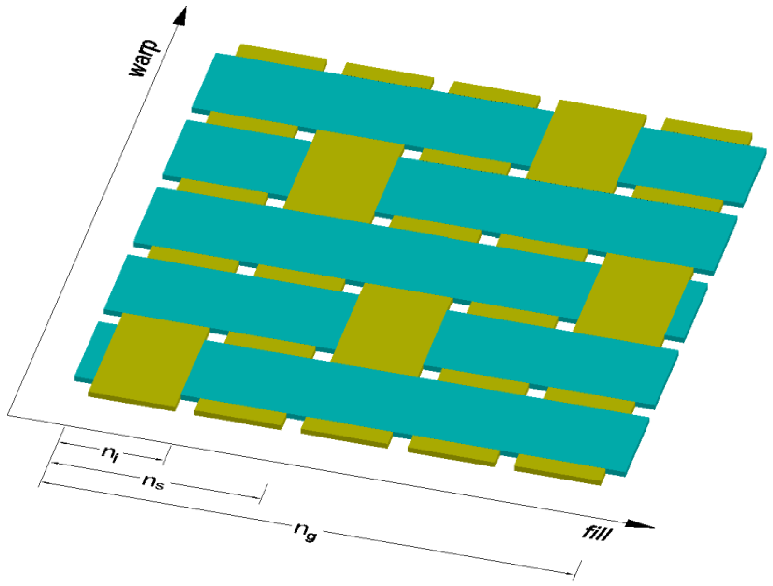
The
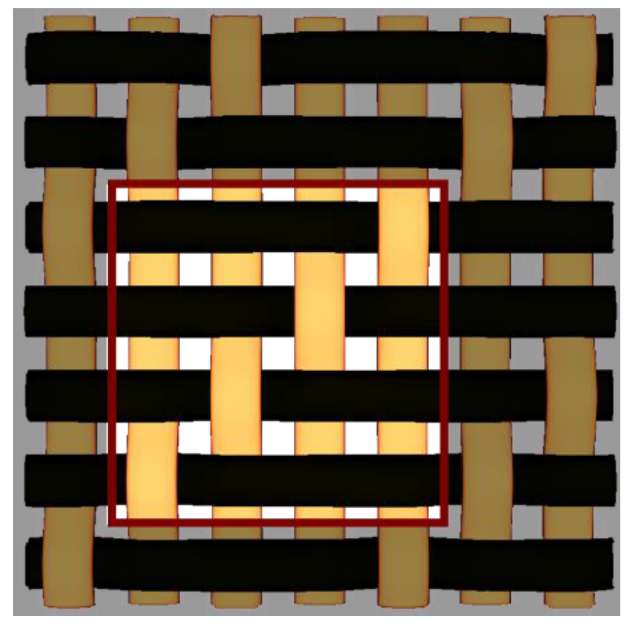
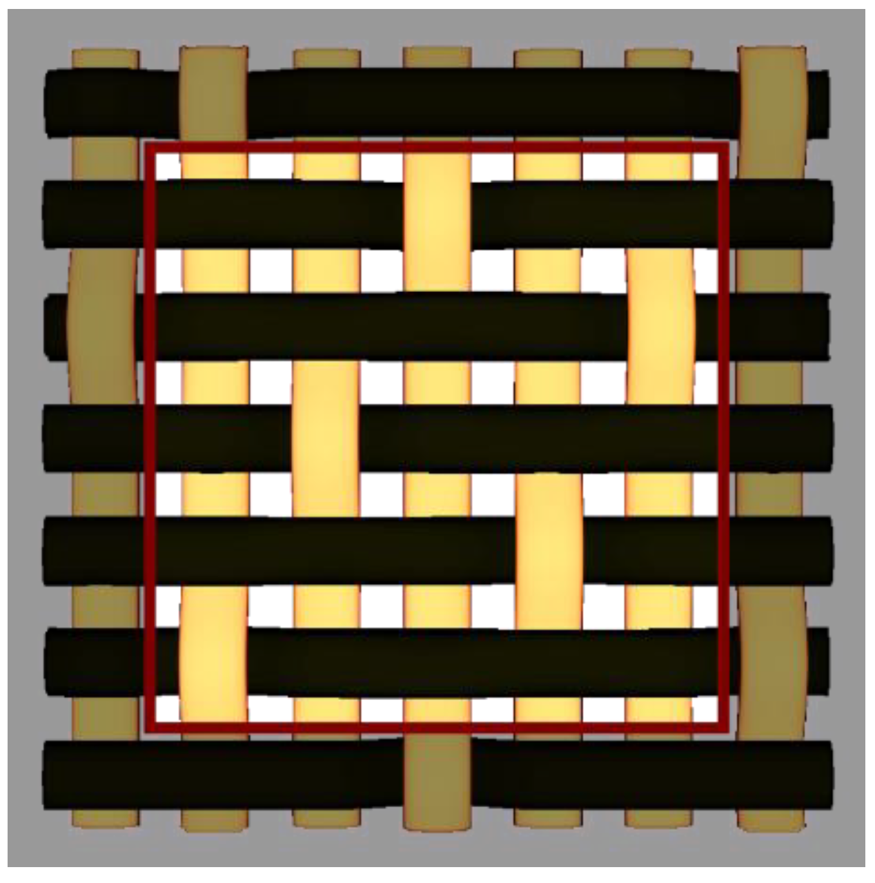
RUC is defined as the smallest essential piece of a composite that keeps repeating itself over the whole material and it defines (at a meso-scale) the structure of the composite [
31,
32,
33]. For example, the five harness satin (5/2/1) is a planar, orthogonal, square fabric made of two perpendicular tows, each consisting of a bunch of fibers. The tows laid down in the x direction of the lamina are called fills and the tows aligned at a right angle, in the y direction, are called warps; in
Figure 1:
—number of sub-cells in one direction of the RUC (harness); in the case of 5/2/1 satin, = 5;
—number of sub-cells between consecutive interlacing regions (shift); in the case of 5/2/1 satin, = 2;
—number of sub-cells in the interlacing region; in the case of satin 5/2/1, = 1.
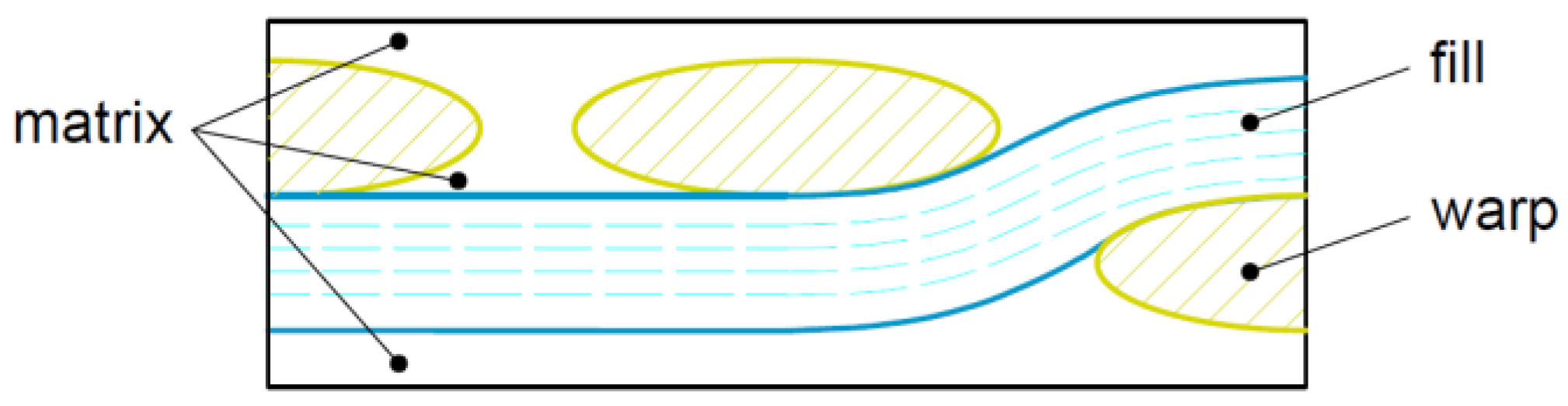
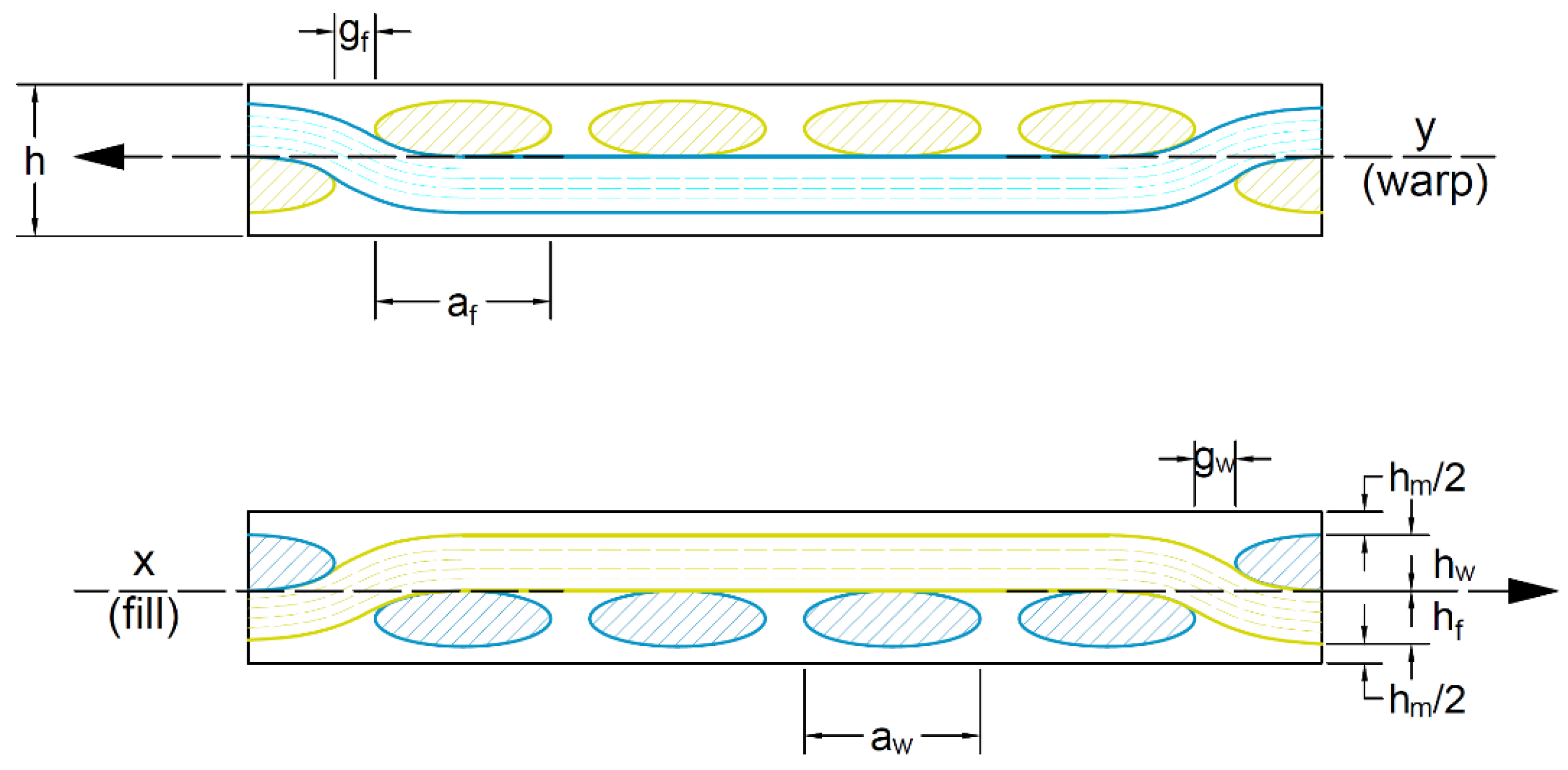
The following geometric parameters are introduced to facilitate the modelling and the implementation of the specific geometry in the software,
Figure 2:
and —the tow width for fill and warp, respectively;
and —the tow height for fill and warp, respectively;
and —the gap between two consecutive tows for fill or warp, respectively;
is the neat matrix thickness.
Based on the geometry specific to the unit cell, a full mechanical analysis can be performed. Starting from the predefined constituent’s characteristics (epoxy resin and E-glass fibers), the input parameters at the meso-scale level are the geometrical parameters corresponding to the
RUC, associated with the laminate stacking sequence (
LSS). The
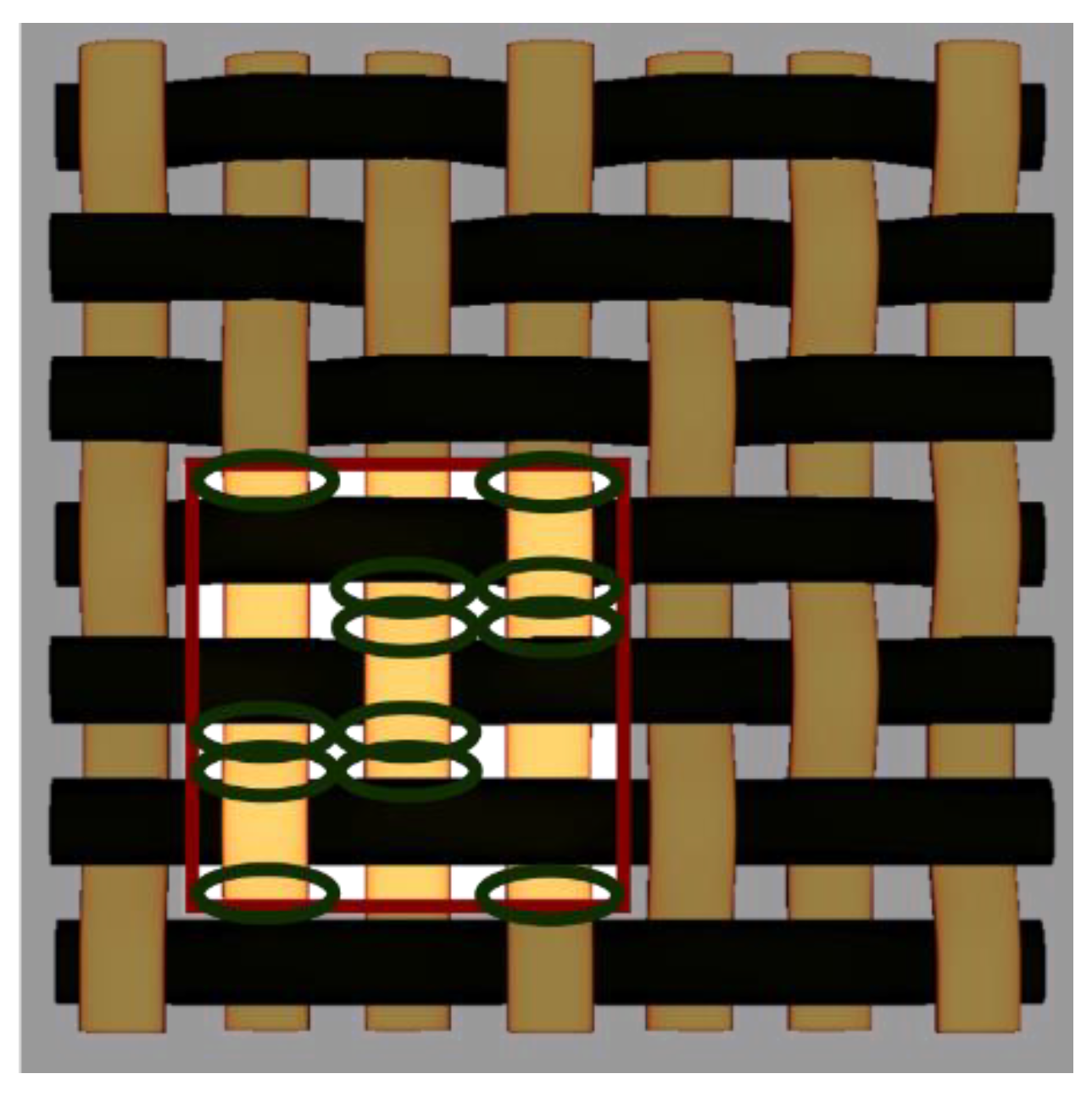
RUC characterizes the material geometry, being divided into individual primary elements, by discretization (a process specific to the
FEM),
Figure 3. The finer the gradient of discretization is, the more accurate the results are, but at the cost of increased computing power. Every primary element is then considered as an asymmetric laminate of its own, having five layers made of fill, matrix or warp and a local
LSS, which depends on its relative position inside the
RUC. For this substructure, the stiffness of each tow is evaluated based on its undulation, a parameter that also influences the neat matrix distribution.
Superimposing various laminas with distinct
LSS and following the pattern, the extensional stiffness matrix increases accordingly. Knowing the elastic properties and a given load (
), a specific strain (
) can be determined. This strain is altered, when necessary, by the ply angle given by the
LSS. The stresses of constituents (warp, fill and matrix) at any given (
x,
y) position of each layer are then evaluated, using Equation (1).
where:
—the reduced stiffness matrix of the element located at the position (x, y);
—the extensional stiffness matrix of element located at the position (x, y).
Applying the maximum-stress failure criterion for warp and fill, and the von Misses yield criterion for the neat matrix, failure analysis theory is used for every primary element [
34]. Therefore, when a single element fails, the stiffness matrix of the entire composite is degraded by a second-order damage tensor and, thus, the loads are redistributed to the nearby neighboring elements [
35]. More information regarding the yield criteria and degradation of the stiffness matrices can be found in the papers previously published by the authors [
34,
35].
Furthermore, the process is sequentially repeated until the overall strains no longer exhibit any increment, or until the composite fails. To quantify the composite efficiency for a specific set of loading, the global strains should be correlated: the higher the strain is, the more of the strength is utilized and thus, the composite is more efficient.
Although the failure criterions mentioned above are dependent only on the fiber and matrix elastic and strength properties, a general damage failure criterion is controlled not only by these properties, but also by composite manufacturing factors, such as the processing conditions and the fiber surface treatments [
36,
37]. Moreover, the accurate prediction of the composite true stress–strain state asks for the evaluation of some key parameters (the relative slippage displacement between the matrix interface and the debonded fibers, the true stress effect, the matrix plasticity, etc.), which define the constitutive relations of the composite outside the elastic range [
38]. This approach may be applied based on a unified elastic–plastic constitutive analysis model (e.g., bridging model). However, although the bridging model involves only analytical formulae (in closed form), the implementation of such a high amount of input data in the presale version of the SOMGA software will substantially increase the computational time. In the following versions of the SOMGA software, the improvement in the accuracy and the refinement of the results through the bridging model are set as objectives.
3. Composite Optimization Using SOMGA Software
The
SOMGA software uses a search optimization approach that is based on the classical principles of genetics and natural selection. Thus, it enables a population consisting of a large number individuals to continuously evolve by the rules of selection, a case that maximizes a specific fitness that is equivalent to minimizing a specific “
kost” function. The latter, whose role is basically to attach a score to the composites in order to be able to rank them inside a group, is a combination of the in-plane strains (
), altered by some key factors. Thus, the smallest “
kost” is granted to a composite with the highest overall strain (optimum efficiency), while a failed composite receives a high “
kost”; see Equation (2). If the laminate does not fail, the number of plies in the
LSS should be maintained as small as possible and the largest strain should be guided towards the direction of the highest load.
where:
, and —the external loads, applied in x, y directions, respectively, and in the xy plane;
—the strains of the material in x, y directions and in the xy plane;
, , —1 if the laminate fails in the corresponding direction and 0 in any other ways;
nop—the number of plies in the LSS.
The geometry of the RUC as well as the LSS are the parameters to be optimized. The number of layers is considered a key parameter and the software tries to keep it at minimum, since fewer plies means smaller manufacturing costs. The ”kost” function is resource consuming and slow; thus, to speed up the convergence, some particularities were imposed:
a multiprocessor, multicore architecture and parallel calculus are utilized to determine the ”kost” of all individuals in a generation;
every determined ”kost” is stored in a database in order to avoid performing the same calculus more than once;
for the best starting point in a vast solution domain, firstly it is determined the maximum number of plies that is necessary for a laminate to avoid failure.
All internal parameters of
SOMGA, specific to the genetic algorithms branch, are carefully chosen to match the optimization problem, as detailed in previous works [
24,
29].
4. The Starting Point
The aim is to design the optimum satin-reinforced composite that can withstand the following external loads (the loads were chosen randomly to illustrate the capability of defining a 3D force vector):
,
and
. In order to obtain that result, the laminate was optimized with the
SOMGA, as previously introduced. The materials utilized were E-glass fibers (as woven fabric) and epoxy resin. The chosen volume fraction for fill and warp is 0.70. The mechanical characteristics of the constituent materials are given in
Table 1.
where:
E1 = E2 = E—the longitudinal, respective transverse modulus of elasticity of the composite constituents (since both materials are isotropic, the longitudinal modulus of elasticity = the transverse modulus of elasticity);
= = —Poisson’s ratios in (1,2) and (2,3) planes, respectively (since both materials are isotropic, the Poisson’s ratios are the same in both (1,2) and (2,3) planes);
—the shear modulus of elasticity in the plane (1,2);
— the tensile strength of the corresponding constituents;
— the shear strength of the corresponding constituents.
The geometrical parameters that require optimization are classified in two categories: continuous and discrete. For each parameter corresponding to the continuous category, a specific interval of possible values is predefined, while every discrete parameter receives a particular set of values. The parameters related to the
RUC to be optimized are listed in
Table 2.
The other parameters related to
LSS are shown in
Table 3.
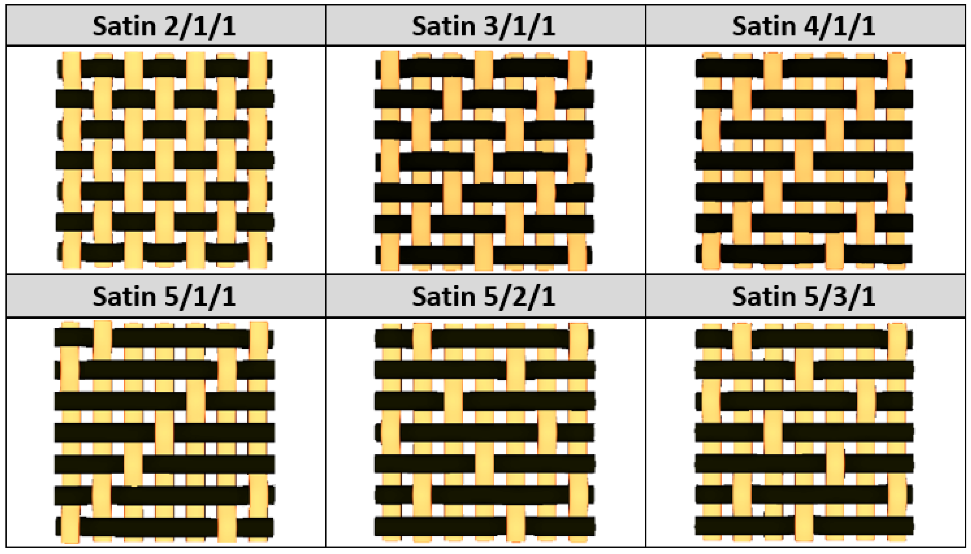
By choosing various types of woven fabric as composite reinforcements, the authors were focused on studying the influence that the undulation has over the number of plies. Using satin 2/1/1 (known as plain wave), satin 3/1/1, satin 4/1/1, satin 5/1/1, satin 5/2/1 and satin 5/3/1 textiles, the undulation counts over the same fabric area can be found. Then, by counting the number of layers and the thickness of each composite type, an estimation of how crimping affects the efficiency of the composite is made, remembering that every material is optimized for the same loads. The fabrics utilized in this paper are shown in
Figure 4.
5. Results and Discussion
5.1. Optimisation Using SOMGA for Satin 2/1/1 Fabric
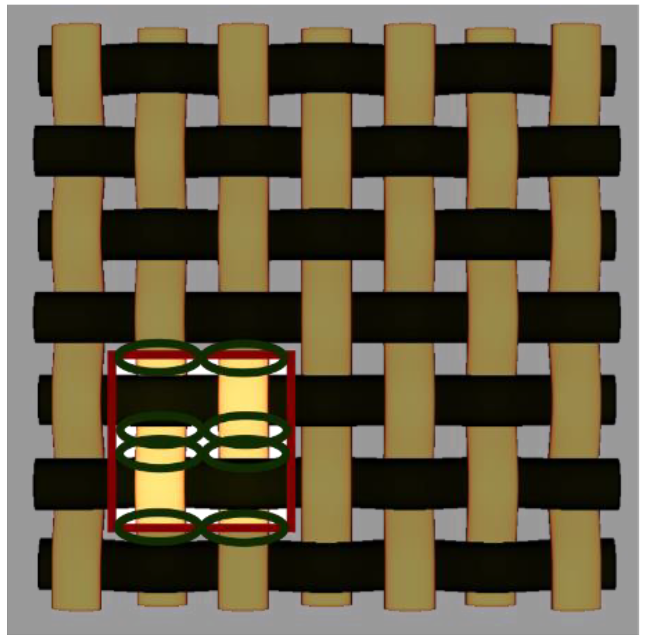
In the first case, the goal is to identify the best composite with the smallest thickness, optimizing all internal geometrical parameters and starting with a plain wave as the reinforcement type; see
Figure 3. The
RUC, consisting of 2 × 2 yarns, is illustrated in
Figure 5.
The number of undulations is defined as the number of times the warp yarns crimp when exchanging position with fill yarns, relative to the middle plane. For example, in the case of satin 2/1/1, the undulation count for the warp is considered to be 8 for the
RUC zone (
) and 98 for the whole reference area. To quantify the undulation density, the current undulation count is compared to a reference one. This reference is the count of the most-crimpy woven fabric possible, namely, the plain wave. The undulations density (
) is the undulation count for the
RUC in relation with the plain wave count for the same
RUC area (
). In this particular case of a plain weave,
; see Equation (3).
The best found solution consists of a laminate with 32 layers and the
LSS given in
Table 4.
5.2. Optimisation Using SOMGA for Satin 3/1/1 Fabric
In the second optimization scenario, a satin 3/1/1 fabric was chosen as composite reinforcement.
Figure 6 illustrates the fabric and the corresponding
RUC. The number of undulations in this case is 12 for the
RUC, the textile being less crimpy than in the first case.
The resulted undulation density (
) is this time only 66%, as given by the Equation (4).
Similar to the first case, all geometrical
RUC and
LSS parameters were to be optimized by the program. The algorithm was run multiple times with a population of 50 individuals per generation. The solution found consists of a laminate with only 26 layers, having the geometrical parameters listed in
Table 5.
5.3. Optimisation Using SOMGA for Satin 4/1/1 Fabric
In this scenario, a satin 4/1/1 fabric was utilized as reinforcement. The fabric and its
RUC are shown in
Figure 7. The number of undulations in this case is 16 for the
RUC and the undulation density (
) is 50%, Equation (5).
The solution found consists of a laminate with 22 layers, having the geometrical parameters for the
RUC and
LSS given in
Table 6.
5.4. Optimisation Using SOMGA for Satin 5/1/1 Fabric
In this case, a satin 5/1/1 fabric was utilized as reinforcement. The fabric and its
RUC are shown in
Figure 8. The number of undulations for the
RUC is 18 (smaller than before) and the undulation density (
) is 36%, as shown in Equation (6).
The solution obtained is a laminate with 18 layers, having the geometrical parameters for the
RUC and
LSS given in
Table 7.
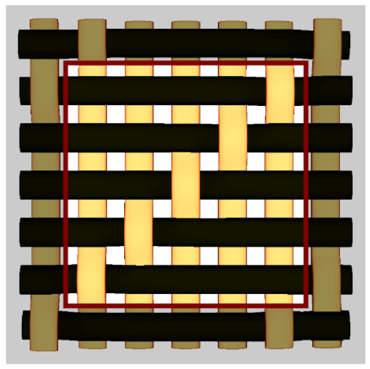
5.5. Optimisation Using SOMGA for Satin 5/2/1 Fabric
In this fifth case study, the chosen reinforcement was a satin 5/2/1 fabric. The fabric and its
RUC are shown in
Figure 9. The number of undulations for the
RUC is 20 and the undulation density (
) is 40%, as per Equation (7).
The solution found in this case is a laminate with 15 layers, having the geometrical parameters for the
RUC and
LSS given in
Table 8.
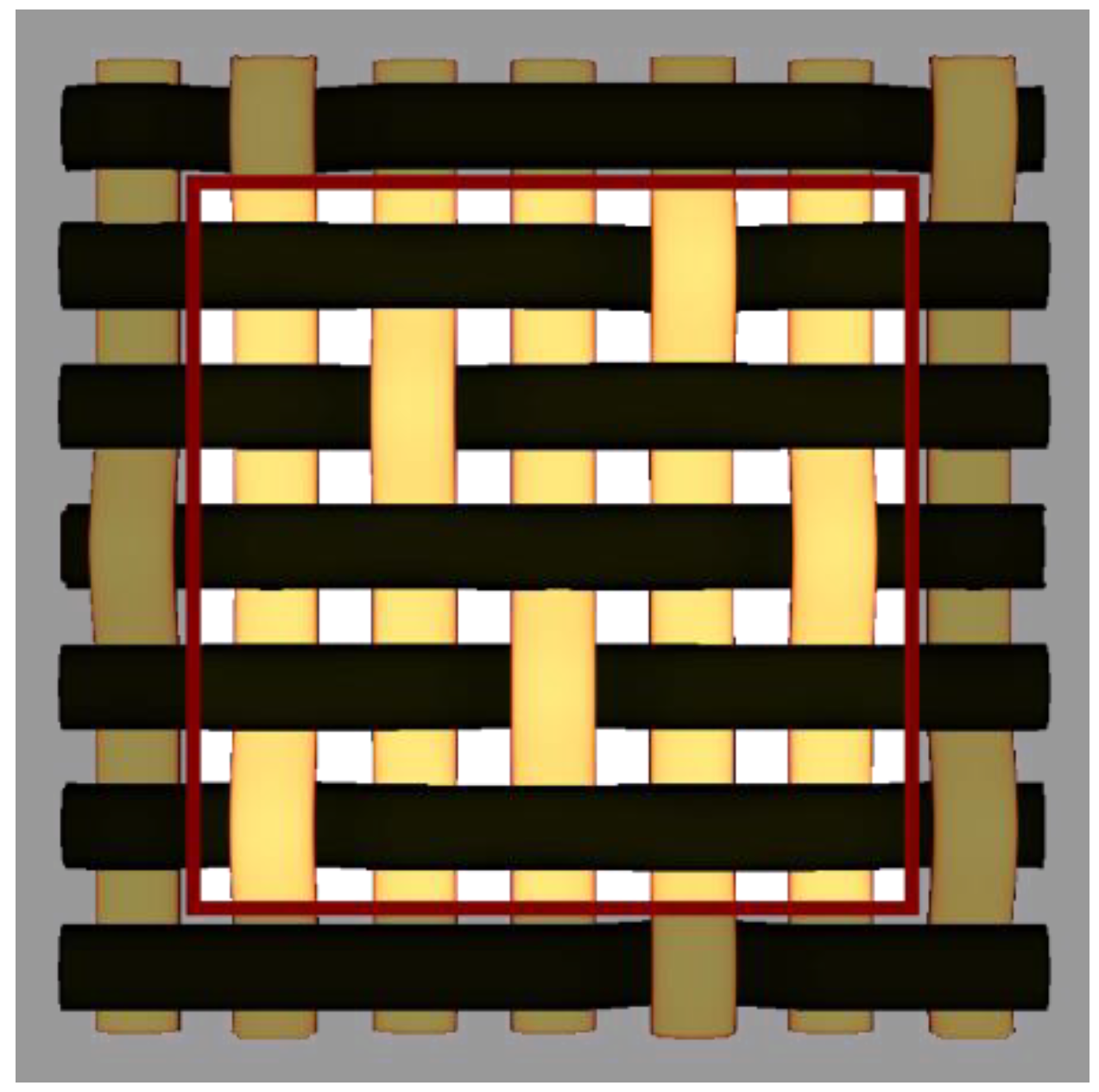
5.6. Optimisation Using SOMGA for Satin 5/3/1 Fabric
In the sixth case, the program was instructed to use a satin 5/3/1 fabric. The fabric and its
RUC are shown in
Figure 10. The number of undulations for the
RUC and the undulation density (
) are the same as in the previous case, equal to 20; therefore, the density is 40%.
The solution found consists of a laminate with 16 layers, having the geometrical parameters for the
RUC and
LSS given in
Table 9.
5.7. Overall Results and Discutions
All results are put together in
Table 10. The ply thickness (
PT) consists of the combined heights of the fill, warp and neat matrix, as can be seen in Equation (8). The laminate thickness (
LT) is the
PT multiplied by the number of layers.
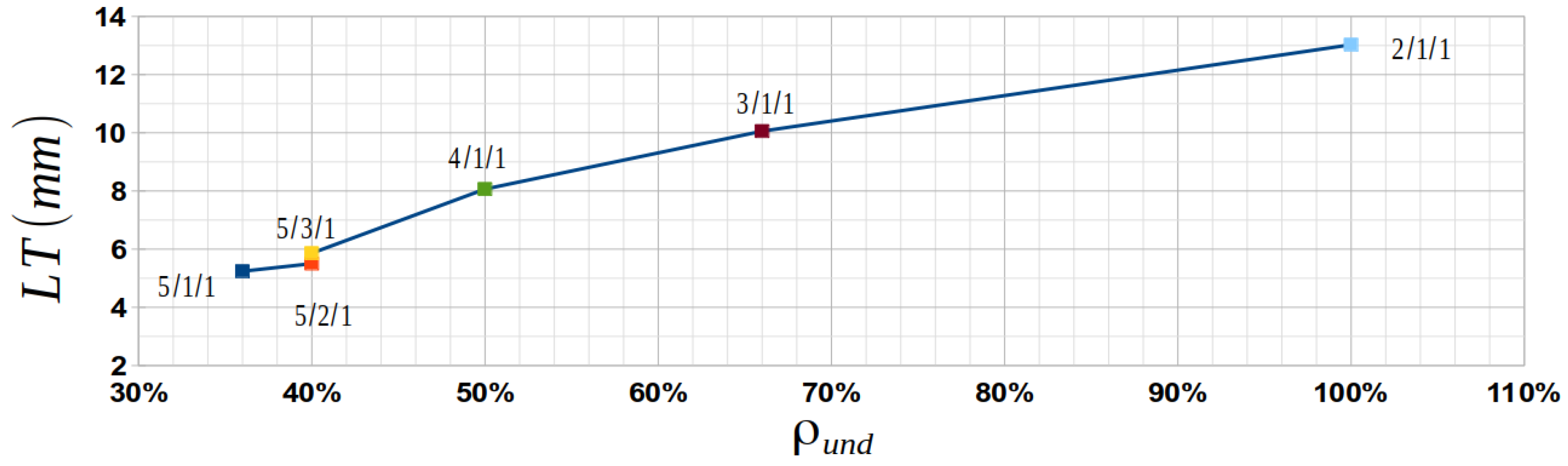
By looking at the data from
Table 10, it can be seen that the
LT is directly related to
in particular and to the fabric type in general; see
Figure 11. The plain-weave fabric (satin 2/1/1), which is the crimpiest of all the textiles (with
), requires the thickest laminate (13.026 mm), with the largest number of plies (32). At the other end, the satin 5/1/1 fabric has the smallest undulation density
) and the smallest
LT (5.240 mm). In this situation, the number of layers (18) is not the smallest number from all the fabrics; this aspect can be explained by looking at the thickness of the ply, which is only 0.291 mm—the smallest number of all.
In the case of the satin 5/2/1 fabric, the optimization software found as the best solution a laminate with 15 layers, which is the smallest number of layers overall. By looking at statistics, this makes sense, because the PT is 0.367 mm, thus having a lamina thicker in this situation than in the satin 5/1/1 case. It is obvious that the undulation of the yarns in reinforcement influences the strength of the laminated composite. The more undulated the tows are, the more chances there are that various sections of them are not aligned in the desired direction, thus decreasing their local strength. Ideally, for maximum strength, the fibers inside tows should be always straight, but this is not possible in practice. In this situation, undulations can be closed to a minimum by using satin /1/1 as reinforcement, where the harness () is five or more, as long as the fabric stays in one piece (the tows do not become loose).
As far as using satin 5/1/1, satin 5/2/1 or satin 5/3/1, there is insignificant differences between them, both in undulation (given by ) and in strength (measured by LT). Therefore, the shift () is not important, as their price and availability are the only factors for favoring one over the others. If the smallest number of plies is considered the most important criterion of the composite-manufacturing process, the SOMGA software can achieve better results by locking, from the beginning, the lamina fabric geometry, therefore imposing the same lamina thickness for all fabric types. Starting from this premise, the optimization process will focus only on LSS, resulting in the absolute minimum number of layers. Another solution would be to increase as much as possible the actual importance factor for the number of plies inside the “kost” function.


 ,
, 


