
Role of Surface Topography in the Superhydrophobic Effect—Experimental and Numerical Studies


 ,
,  and
and 
Abstract
:1. Introduction
2. Materials and Methods
- -
- Velocity inlet with 0 m·s−1 velocity magnitude on the upper edge
- -
- Outflow on the sides of simulation domain
- -
- Wall with No Slip condition and static contact angle on the lower boundary representing the material’s surface.
3. Results and Discussion
4. Conclusions
Author Contributions
Funding
Institutional Review Board Statement
Informed Consent Statement
Data Availability Statement
Conflicts of Interest
References
- Li, X.M.; Reinhoudt, D.; Crego-Calama, M. What do we need for a superhydrophobic surface? A review on the recent progress in the preparation of superhydrophobic surfaces. Chem. Soc. Rev. 2007, 36, 1350–1368. [Google Scholar] [CrossRef]
- Vinogradova, O.I.; Belyaev, A.V. Wetting, roughness and flow boundary conditions. J. Phys. Condens. Matter 2011, 23, 184104. [Google Scholar] [CrossRef] [Green Version]
- Young, T., III. An essay on the cohesion of fluids. Philos. Trans. R. Soc. London 1805, 95, 65–87. [Google Scholar] [CrossRef]
- Grewal, H.S.; Cho, I.J.; Oh, J.E.; Yoon, E.S. Effect of topography on the wetting of nanoscale patterns: Experimental and modeling studies. Nanoscale 2014, 6, 15321–15332. [Google Scholar] [CrossRef]
- Wolansky, G.; Marmur, A. Apparent contact angles on rough surfaces: The Wenzel equation revisited. Colloids Surfaces A Physicochem. Eng. Asp. 1999, 156, 381–388. [Google Scholar] [CrossRef]
- Cassie, A.B.D. Contact angles. Discuss. Faraday Soc. 1948, 3, 11–16. [Google Scholar] [CrossRef]
- Marmur, A. The lotus effect: Superhydrophobicity and metastability. Langmuir 2004, 20, 3517–3519. [Google Scholar] [CrossRef]
- Guo, Z.; Liu, W.; Su, B.L. Superhydrophobic surfaces: From natural to biomimetic to functional. J. Colloid Interface Sci. 2011, 353, 335–355. [Google Scholar] [CrossRef]
- Nishino, T.; Meguro, M.; Nakamae, K.; Matsushita, M.; Ueda, Y. The lowest surface free energy based on -CF3 alignment. Langmuir 1999, 15, 4321–4323. [Google Scholar] [CrossRef]
- Cassie, A.B.D.; Baxter, S. Wettability of porous surfaces. Trans. Faraday Soc. 1944, 40, 546–551. [Google Scholar] [CrossRef]
- Gregorčič, P.; Conradi, M.; Hribar, L.; Hočevar, M. Long-term influence of laser-processing parameters on (Super)hydrophobicity development and stability of stainless-steel surfaces. Materials 2018, 11, 2240. [Google Scholar] [CrossRef] [PubMed] [Green Version]
- Kreder, M.J.; Alvarenga, J.; Kim, P.; Aizenberg, J. Design of anti-icing surfaces: Smooth, textured or slippery? Nat. Rev. Mater. 2016, 1, 15003. [Google Scholar] [CrossRef]
- Shirtcliffe, N.J.; McHale, G.; Atherton, S.; Newton, M.I. An introduction to superhydrophobicity. Adv. Colloid Interface Sci. 2010, 161, 124–138. [Google Scholar] [CrossRef] [PubMed] [Green Version]
- Yeong, Y.H.; Milionis, A.; Loth, E.; Sokhey, J.; Lambourne, A. Atmospheric Ice Adhesion on Water-Repellent Coatings: Wetting and Surface Topology Effects. Langmuir 2015, 31, 13107–13116. [Google Scholar] [CrossRef]
- Barrios, J.M.; Romero, P.E. Improvement of surface roughness and hydrophobicity in PETG parts manufactured via fused deposition modeling (FDM): An application in 3D printed self-cleaning parts. Materials 2019, 12, 2499. [Google Scholar] [CrossRef] [Green Version]
- Giacomello, A.; Meloni, S.; Chinappi, M.; Casciola, C.M. Cassie-baxter and wenzel states on a nanostructured surface: Phase diagram, metastabilities, and transition mechanism by atomistic free energy calculations. Langmuir 2012, 28, 10764–10772. [Google Scholar] [CrossRef]
- Bhushan, B.; Nosonovsky, M. The rose petal effect and the modes of superhydrophobicity. Philos. Trans. R. Soc. A Math. Phys. Eng. Sci. 2010, 368, 4713–4728. [Google Scholar] [CrossRef]
- Kozera, R.; Przybyszewski, B.; Krawczyk, Z.D.; Boczkowska, A.; Sztorch, B.; Przekop, R.E.; Barbucha, R.; Tański, M.; Casas, X.G.; Borras, A. Hydrophobic and anti-icing behavior of uv-laser-treated polyester resin-based gelcoats. Processes 2020, 8, 1642. [Google Scholar] [CrossRef]
- Irzmańska, E.; Korzeniewska, E.; Pawlak, R.; Tomczyk, M.; Smejda-Krzewicka, A.; Adamus-Włodarczyk, A. Enhanced Hydrofobicity of Polymers for Personal Protective Equipment Achieved by Chemical and Physical Modification. Materials 2022, 15, 106. [Google Scholar] [CrossRef]
- Bhushan, B.; Her, E.K. Fabrication of Superhydrophobic Surfaces with High and Low Adhesion Inspired from Rose Petal. Langmuir 2010, 26, 8207–8217. [Google Scholar] [CrossRef]
- Somrang, W.; Denchitcharoen, S.; Eiamchai, P.; Horprathum, M.; Chananonnawathorn, C. Superhydrophobic and antireflective surface of nanostructures fabricated by CF4 plasma etching. Mater. Today Proc. 2018, 5, 13879–13885. [Google Scholar] [CrossRef]
- Leese, H.; Bhurtun, V.; Lee, K.P.; Mattia, D. Wetting behaviour of hydrophilic and hydrophobic nanostructured porous anodic alumina. Colloids Surf. A Physicochem. Eng. Asp. 2013, 420, 53–58. [Google Scholar] [CrossRef] [Green Version]
- He, H.; Wu, W.; Xi, Z.; Ma, Z.; Zhang, L.; Wang, C.; Sun, L. Time dependency of superhydrophilic and superhydrophobic surfaces produced by nanosecond laser irradiation assisted by post-annealing and silanization. Appl. Surf. Sci. 2022, 586, 152819. [Google Scholar] [CrossRef]
- Gao, J.; Wu, Y.; Zhang, Z.; Zhao, D.; Zhu, H.; Xu, K.; Liu, Y. Achieving amorphous micro-nano superhydrophobic structures on quartz glass with a PTFE coating by laser back ablation. Opt. Laser Technol. 2022, 149, 107927. [Google Scholar] [CrossRef]
- Meuler, A.J.; Smith, J.D.; Varanasi, K.K.; Mabry, J.M.; Mckinley, G.H.; Cohen, R.E. Relationships between Water Wettability and Ice Adhesion. ACS Appl. Mater. Interfaces 2010, 2, 3100–3110. [Google Scholar] [CrossRef] [PubMed]
- Nowak, A.P.; Gross, A.F.; Sherman, E.; Seebergh, J.E.; Dalby, G.R.; Berry, D.H. Coatings, Coating Compositions, and Methods For Delaying Ice Formation. US Patent 20150044420A1, 12 February 2015. [Google Scholar]
- Tuteja, A.; Kota, A.K.; Kwon, G.; Mabry, J.M. Superhydrophilic and oleophobic porous materials and methods for making and using the same. US Patent 9186631B2, 17 November 2011. [Google Scholar]
- Zhang, H.; Lamb, R.N.; Jones, A.W. Durable superhydrophobic coating. US Patent 8513342B2, 20 August 2004. [Google Scholar]
- Onda, T.; Shibuichi, S.; Satoh, N.; Tsujii, K. Super-Water-Repellent Fractal Surfaces. Langmuir 1996, 12, 2125–2127. [Google Scholar] [CrossRef]
- Varanasi, K.K.; Deng, T.; Smith, J.D.; Hsu, M.; Bhate, N. Frost formation and ice adhesion on superhydrophobic surfaces. Appl. Phys. Lett. 2010, 97, 95–98. [Google Scholar] [CrossRef]
- Kulinich, S.A.; Farzaneh, M. How wetting hysteresis influences ice adhesion strength on superhydrophobic surfaces. Langmuir 2009, 25, 8854–8856. [Google Scholar] [CrossRef]
- Menini, R.; Ghalmi, Z.; Farzaneh, M. Highly resistant icephobic coatings on aluminum alloys. Cold Reg. Sci. Technol. 2011, 65, 65–69. [Google Scholar] [CrossRef]
- Farhadi, S.; Farzaneh, M.; Kulinich, S.A. Anti-icing performance of superhydrophobic surfaces. Appl. Surf. Sci. 2011, 257, 6264–6269. [Google Scholar] [CrossRef]
- Tourkine, P.; Le Merrer, M.; Quéré, D. Delayed Freezing on Water Repellent Materials. Langmuir 2009, 25, 7214–7216. [Google Scholar] [CrossRef]
- Wang, F.; Li, C.; Lv, Y.; Lv, F.; Du, Y. Ice accretion on superhydrophobic aluminum surfaces under low-temperature conditions. Cold Reg. Sci. Technol. 2010, 62, 29–33. [Google Scholar] [CrossRef]
- Kozera, R.; Przybyszewski, B.; Żołyńska, K.; Boczkowska, A.; Sztorch, B.; Przekop, R.E. Hybrid modification of unsaturated polyester resins to obtain hydro-and icephobic properties. Processes 2020, 8, 1635. [Google Scholar] [CrossRef]
- Varanasi, K.K.; Deng, T.; Hsu, M.F.; Bhate, N. Design of Superhydrophobic Surfaces for Optimum Roll-Off and Droplet Impact Resistance. In Proceedings of the ASME 2008 International Mechanical Engineering Congress and Exposition, Boston, MA, USA, 31 October–6 November 2008; pp. 637–645. [Google Scholar]
- Khaskhoussi, A.; Calabrese, L.; Patané, S.; Proverbio, E. Effect of Chemical Surface Texturing on the Superhydrophobic Behavior of Micro–Nano-Roughened AA6082 Surfaces. Materials 2021, 14, 7161. [Google Scholar] [CrossRef]
- Król, P.; Król, B. Surface free energy of polyurethane coatings with improved hydrophobicity. Colloid Polym. Sci. 2012, 290, 879–893. [Google Scholar] [CrossRef] [PubMed] [Green Version]
- Liu, M.; Wang, S.; Jiang, L. Bioinspired multiscale surfaces with special wettability. MRS Bull. 2013, 38, 375–382. [Google Scholar] [CrossRef]
- Herminghaus, S. Roughness-induced non-wetting. Eur. Lett. 2000, 52, 165–170. [Google Scholar] [CrossRef]
- Feng, L.; Zhang, Y.; Xi, J.; Zhu, Y.; Wang, N.; Xia, F.; Jiang, L. Petal effect: A superhydrophobic state with high adhesive force. Langmuir 2008, 24, 4114–4119. [Google Scholar] [CrossRef]
- Miwa, M.; Nakajima, A.; Fujishima, A.; Hashimoto, K.; Watanabe, T. Effects of the Surface Roughness on Sliding Angles of Water Droplets on Superhydrophobic Surfaces. Langmuir 2000, 16, 5754–5760. [Google Scholar] [CrossRef]
- Hirt, C.W.; Nichols, B.D. Volume of fluid (VOF) method for the dynamics of free boundaries. J. Comput. Phys. 1981, 39, 201–225. [Google Scholar] [CrossRef]
- Alla, H.; Freifer, S.; Roques-Carmes, T. A computational fluid dynamics model using the volume of fluid method for describing the dynamics of spreading of Newtonian fluids. Colloids Surf. A Physicochem. Eng. Asp. 2011, 386, 107–115. [Google Scholar] [CrossRef]
- Arzpeyma, A.; Bhaseen, S.; Dolatabadi, A.; Wood-Adams, P. A coupled electro-hydrodynamic numerical modeling of droplet actuation by electrowetting. Colloids Surf. A Physicochem. Eng. Asp. 2008, 323, 28–35. [Google Scholar] [CrossRef]
- El Ganaoui, M.; Mohammed, B.; Alla, H. Numerical Investigation of a Drop/Surface Interaction; Begel House Inc.: Danbury, CT, USA, 2006; ISBN 1-56700-225-0. [Google Scholar]
- Nichita, B.A.; Zun, I.; Thome, J.R. A VOF method coupled with a dynamic contact angle model for simulation of two-phase flows with partial wetting. In Proceedings of the 7th International Conference on Multiphase Flow, ICMF 2010, Tampa, FL, USA, 30 May–4 June 2010; pp. 1–8. [Google Scholar]
- Gunjal, P.R.; Ranade, V.V.; Chaudhari, R.V. Experimental and computational study of liquid drop over flat and spherical surfaces. Catal. Today 2003, 79–80, 267–273. [Google Scholar] [CrossRef]
- Gunjal, P.R.; Ranade, V.V.; Chaudhari, R. V Dynamics of drop impact on solid surface: Experiments and VOF simulations. AIChE J. 2005, 51, 59–78. [Google Scholar] [CrossRef]
- Liu, C.; Liu, Q.; Jin, R.; Lin, Z.; Qiu, H.; Xu, Y. Mechanism analysis and durability evaluation of anti-icing property of superhydrophobic surface. Int. J. Heat Mass Transf. 2020, 156, 119768. [Google Scholar] [CrossRef]
- Chamakos, N.T.; Kavousanakis, M.E.; Boudouvis, A.G.; Papathanasiou, A.G. Droplet spreading on rough surfaces: Tackling the contact line boundary condition. Phys. Fluids 2016, 28, 22105. [Google Scholar] [CrossRef]
- Pilch-Pitera, B. Polyurethane powder coatings containing polysiloxane. Prog. Org. Coat. 2014, 77, 1653–1662. [Google Scholar] [CrossRef]
- Seyfi, J.; Jafari, S.H.; Khonakdar, H.A.; Sadeghi, G.M.M.; Zohuri, G.; Hejazi, I.; Simon, F. Fabrication of robust and thermally stable superhydrophobic nanocomposite coatings based on thermoplastic polyurethane and silica nanoparticles. Appl. Surf. Sci. 2015, 347, 224–230. [Google Scholar] [CrossRef]
- Stalder, A.F.; Kulik, G.; Sage, D.; Barbieri, L.; Hoffmann, P. A snake-based approach to accurate determination of both contact points and contact angles. Colloids Surf. A Physicochem. Eng. Asp. 2006, 286, 92–103. [Google Scholar] [CrossRef] [Green Version]

| Sample | SCA [°] | CAH [°] | RoA [°] |
|---|---|---|---|
| Reference PUR | 85 | 39 | 87 |
| Modified PUR | 107 | 35 | 80 |
| 5by5 | 114 | 18 | 90 |
| 10by5 | 119 | 20 | 45 |
| 20by5 | 115 | 25 | 90 |
| 5by10 | 118 | 23 | 40 |
| 10by10 | 121 | 26 | 90 |
| 20by20 | 136 | 5 | 5 |
| 5by20 | 133 | 24 | 40 |
| 10by20 | 131 | 18 | 35 |
| 20by10 | 115 | 27 | 70 |
| Sample | Experiment | Model | Model (140° Surface Contact Angle) | Model Miwa et al. [43] | ||||
|---|---|---|---|---|---|---|---|---|
| Apparent Contact Angle [°] | Roll-off-Angle [°] | Apparent Contact Angle [°] | Roll-off-Angle [°] | Apparent Contact Angle [°] | Roll-off -Angle [°] | 107 CA [°] | 140 CA [°] | |
| 5by5 | 114 | >90 | 107 | >90 | 113 | >90 | - | - |
| 10by10 | 121 | >90 | 116 | >90 | 122 | >90 | - | - |
| 20by20 | 136 | 5 | 132 | 30 | 138 | 10 | 66 | 27 |
| Surface Pattern | Roll-Off Angle [°] | Apparent Contact Angle [°] | |
|---|---|---|---|
 | Rectangle | >90 | 128 |
 | Rounded rectangle | >90 | 133 |
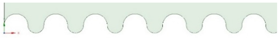 | Circles | >90 | 130 |
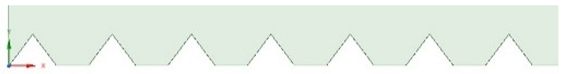 | Spikes | 10 | 167 |
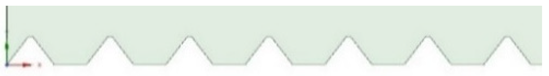 | Rounded spikes | 35 | 166 |
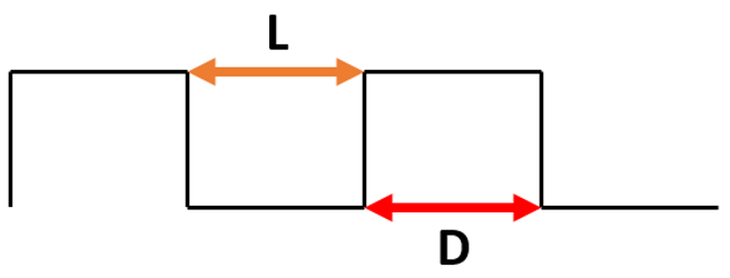 | Surface Pattern L_D [µm] | Roll-Off Angle [°] | Apparent Contact Angle [°] |
| 5_5 | >90 | 145 | |
| 10_5 | >90 | 146 | |
| 15_5 | >90 | 147 | |
| 20_5 | >90 | 149 |
 | Surface Pattern L_D [µm] | Roll-Off Angle [°] | Apparent Contact Angle [°] |
| 5_12 | 15 | 172 | |
| 10_12 | 10 | 169 | |
| 15_12 | 10 | 175 | |
| 20_12 | 5 | 170 |
Publisher’s Note: MDPI stays neutral with regard to jurisdictional claims in published maps and institutional affiliations. |
© 2022 by the authors. Licensee MDPI, Basel, Switzerland. This article is an open access article distributed under the terms and conditions of the Creative Commons Attribution (CC BY) license (https://creativecommons.org/licenses/by/4.0/).
Share and Cite
Haj Ibrahim, S.; Wejrzanowski, T.; Przybyszewski, B.; Kozera, R.; García-Casas, X.; Barranco, A. Role of Surface Topography in the Superhydrophobic Effect—Experimental and Numerical Studies. Materials 2022, 15, 3112. https://doi.org/10.3390/ma15093112
Haj Ibrahim S, Wejrzanowski T, Przybyszewski B, Kozera R, García-Casas X, Barranco A. Role of Surface Topography in the Superhydrophobic Effect—Experimental and Numerical Studies. Materials. 2022; 15(9):3112. https://doi.org/10.3390/ma15093112
Chicago/Turabian StyleHaj Ibrahim, Samih, Tomasz Wejrzanowski, Bartłomiej Przybyszewski, Rafał Kozera, Xabier García-Casas, and Angel Barranco. 2022. "Role of Surface Topography in the Superhydrophobic Effect—Experimental and Numerical Studies" Materials 15, no. 9: 3112. https://doi.org/10.3390/ma15093112
APA StyleHaj Ibrahim, S., Wejrzanowski, T., Przybyszewski, B., Kozera, R., García-Casas, X., & Barranco, A. (2022). Role of Surface Topography in the Superhydrophobic Effect—Experimental and Numerical Studies. Materials, 15(9), 3112. https://doi.org/10.3390/ma15093112