
Tuning of Magnetic Damping in Y3Fe5O12/Metal Bilayers for Spin-Wave Conduit Termination

 , , , ,
  and
and 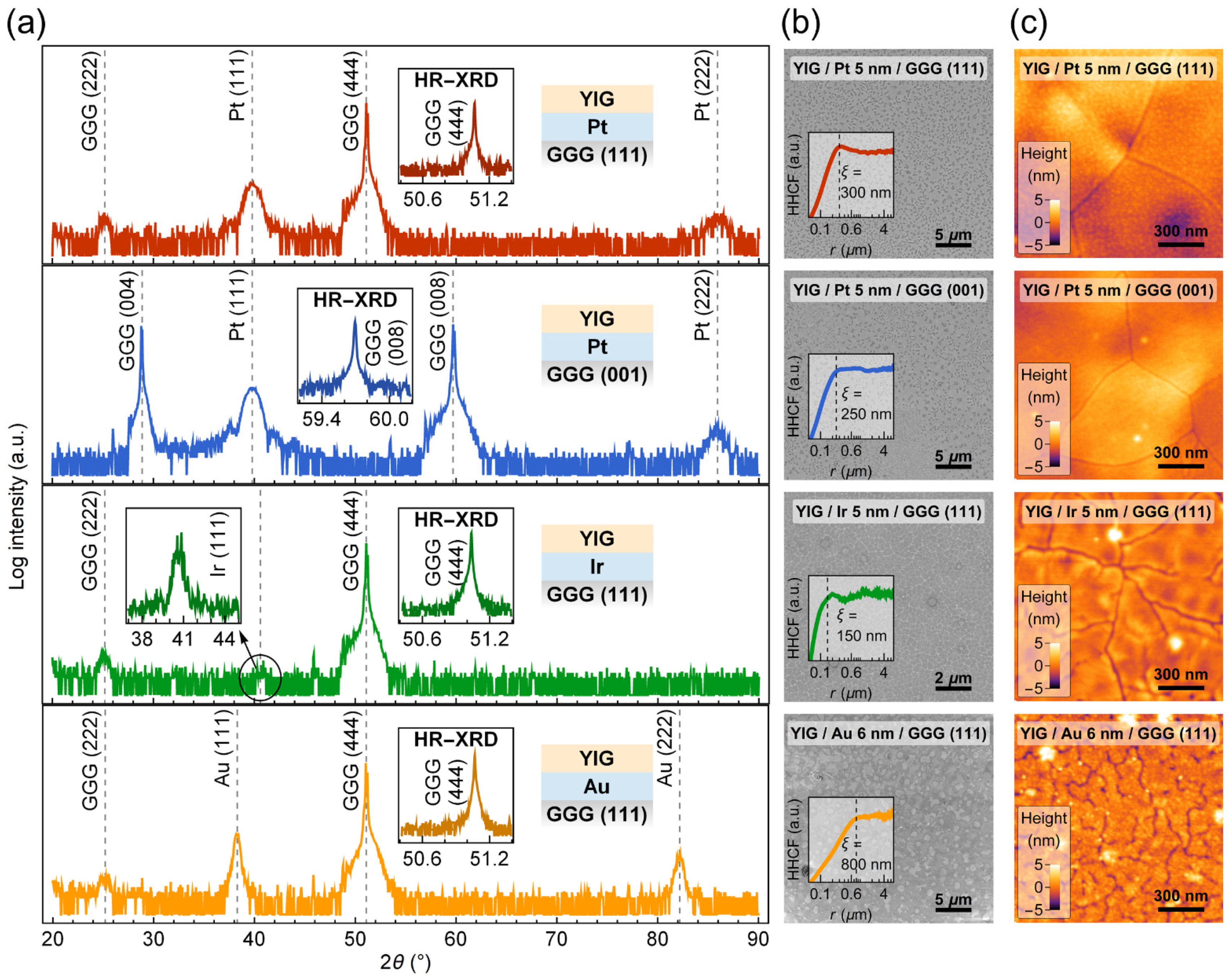
Abstract
1. Introduction
2. Materials and Methods
3. Results and Discussions
3.1. Structural Properties
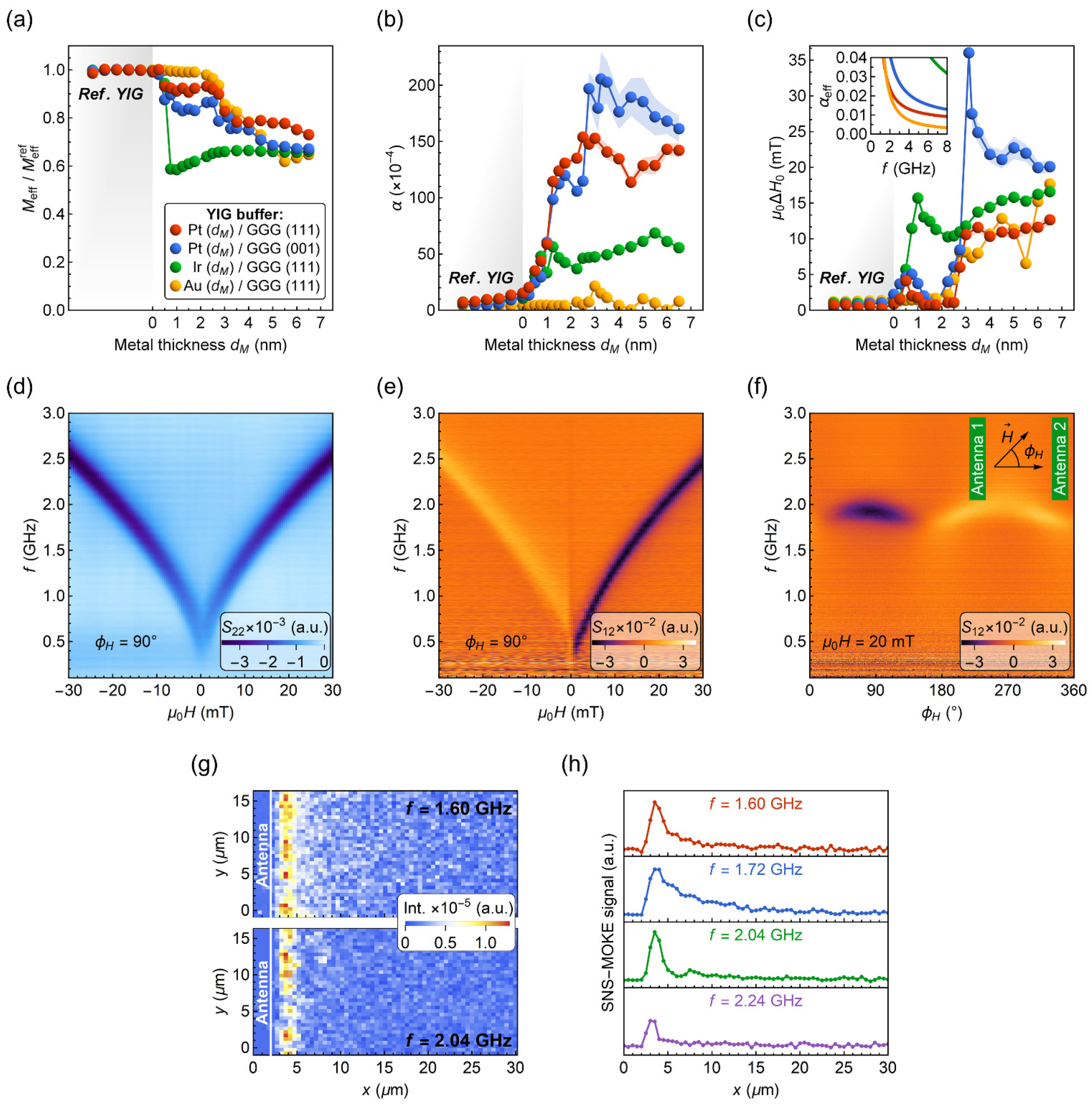
3.2. Magnetization Dynamics
3.3. SW Packet Propagation Characteristics
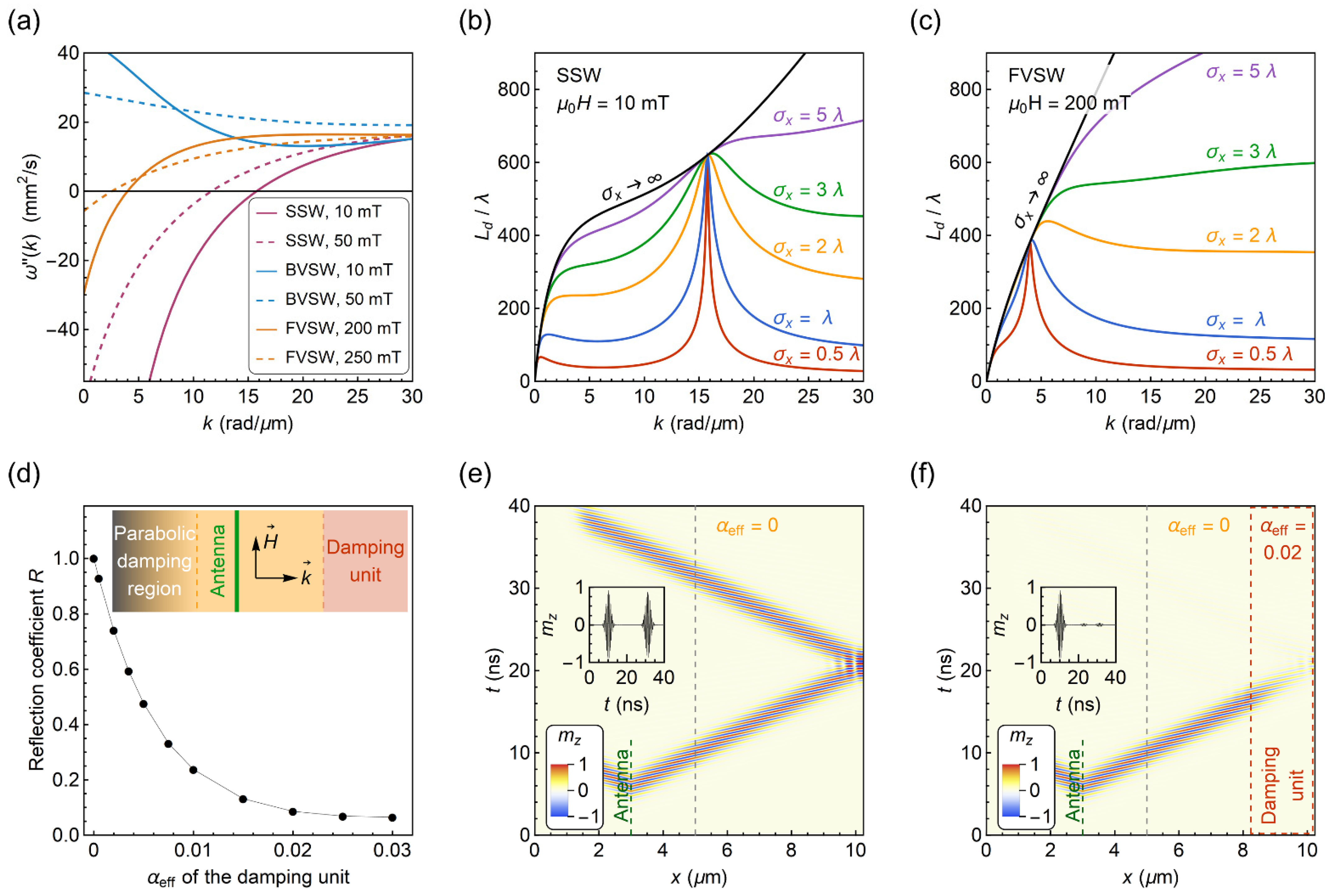
3.4. SW Packet Reflection from a Damping Unit
4. Summary
Supplementary Materials
Author Contributions
Funding
Institutional Review Board Statement
Informed Consent Statement
Data Availability Statement
Conflicts of Interest
References
- Barman, A.; Gubbiotti, G.; Ladak, S.; Adeyeye, A.O.; Krawczyk, M.; Grafe, J.; Adelmann, C.; Cotofana, S.; Naeemi, A.; Vasyuchka, V.I.; et al. The 2021 Magnonics Roadmap. J. Phys. Condens. Matter 2021, 33, 413001. [Google Scholar] [CrossRef] [PubMed]
- Mahmoud, A.; Ciubotaru, F.; Vanderveken, F.; Chumak, A.V.; Hamdioui, S.; Adelmann, C.; Cotofana, S. Introduction to Spin Wave Computing. J. Appl. Phys. 2020, 128, 161101. [Google Scholar] [CrossRef]
- Barman, A.; Mondal, S.; Sahoo, S.; De, A. Magnetization Dynamics of Nanoscale Magnetic Materials: A Perspective. J. Appl. Phys. 2020, 128, 170901. [Google Scholar] [CrossRef]
- Sheng, L.; Chen, J.; Wang, H.; Yu, H. Magnonics Based on Thin-Film Iron Garnets. J. Phys. Soc. Jpn. 2021, 90, 081005. [Google Scholar] [CrossRef]
- Kruglyak, V.V. Chiral Magnonic Resonators: Rediscovering the Basic Magnetic Chirality in Magnonics. Appl. Phys. Lett. 2021, 119, 200502. [Google Scholar] [CrossRef]
- Pirro, P.; Vasyuchka, V.I.; Serga, A.A.; Hillebrands, B. Advances in Coherent Magnonics. Nat. Rev. Mater. 2021, 6, 1114–1135. [Google Scholar] [CrossRef]
- Yang, Y.; Liu, T.; Bi, L.; Deng, L. Recent Advances in Development of Magnetic Garnet Thin Films for Applications in Spintronics and Photonics. J. Alloy. Compd. 2021, 860, 158235. [Google Scholar] [CrossRef]
- Schmidt, G.; Hauser, C.; Trempler, P.; Paleschke, M.; Papaioannou, E.T. Ultra Thin Films of Yttrium Iron Garnet with Very Low Damping: A Review. Phys. Status Solidi 2020, 257, 1900644. [Google Scholar] [CrossRef]
- Hauser, C.; Richter, T.; Homonnay, N.; Eisenschmidt, C.; Qaid, M.; Deniz, H.; Hesse, D.; Sawicki, M.; Ebbinghaus, S.G.; Schmidt, G. Yttrium Iron Garnet Thin Films with Very Low Damping Obtained by Recrystallization of Amorphous Material. Sci. Rep. 2016, 6, 20827. [Google Scholar] [CrossRef]
- Ding, J.; Liu, T.; Chang, H.; Wu, M. Sputtering Growth of Low-Damping Yttrium-Iron-Garnet Thin Films. IEEE Magn. Lett. 2020, 11, 5502305. [Google Scholar] [CrossRef]
- Ding, J.; Liu, C.; Zhang, Y.; Erugu, U.; Quan, Z.; Yu, R.; Mccollum, E.; Mo, S.; Yang, S.; Ding, H.; et al. Nanometer-Thick Yttrium Iron Garnet Films with Perpendicular Anisotropy and Low Damping. Phys. Rev. Appl. 2020, 14, 014017. [Google Scholar] [CrossRef]
- Krysztofik, A.; Coy, L.E.; Kuswik, P.; Załȩski, K.; Głowinski, H.; Dubowik, J. Ultra-Low Damping in Lift-off Structured Yttrium Iron Garnet Thin Films. Appl. Phys. Lett. 2017, 111, 192404. [Google Scholar] [CrossRef]
- Holzmann, C.; Ullrich, A.; Ciubotariu, O.T.; Albrecht, M. Stress-Induced Magnetic Properties of Gadolinium Iron Garnet Nanoscale-Thin Films: Implications for Spintronic Devices. ACS Appl. Nano Mater. 2022, 5, 1023–1033. [Google Scholar] [CrossRef]
- Wu, G.; Wang, D.; Verma, N.; Rao, R.; Cheng, Y.; Guo, S.; Cao, G.; Watanabe, K.; Taniguchi, T.; Lau, C.N.; et al. Enhancing Perpendicular Magnetic Anisotropy in Garnet Ferrimagnet by Interfacing with Few-Layer WTe2. Nano Lett. 2022, 22, 1115–1121. [Google Scholar] [CrossRef] [PubMed]
- Böttcher, T.; Ruhwedel, M.; Levchenko, K.O.; Wang, Q.; Chumak, H.L.; Popov, M.A.; Zavislyak, I.V.; Dubs, C.; Surzhenko, O.; Hillebrands, B.; et al. Fast Long-Wavelength Exchange Spin Waves in Partially Compensated Ga:YIG. Appl. Phys. Lett. 2022, 120, 102401. [Google Scholar] [CrossRef]
- Zhang, Y.; Yang, Q.; Liu, X.; Zhang, D.; Rao, Y.; Zhang, H. Comparison of the Magnetic Properties of Bismuth Substituted Thulium Iron Garnet and Yttrium Iron Garnet Films. AIP Adv. 2021, 11, 065113. [Google Scholar] [CrossRef]
- Syvorotka, I.I.; Sugak, D.; Yakhnevych, U.; Buryy, O.; Włodarczyk, D.; Pieniążek, A.; Zhydachevskyy, Y.; Levintant-Zayonts, N.; Savytskyy, H.; Bonchyk, O.; et al. Investigation of the Interface of Y3Fe5O12/Gd3Ga5O12 Structure Obtained by the Liquid Phase Epitaxy. Cryst. Res. Technol. 2022, 2100180. [Google Scholar] [CrossRef]
- Rao, Y.; Zhang, D.; Jin, L.; Zhong, Z.; Yang, Q.; Li, M.; Li, J.; Yang, Y.; Wang, G.; Gan, G.; et al. Magnetic Properties of a Y3Fe5O12/(TmBi)3(FeGa)5O12 Heterostructure Related to Strain-Induced Magnetic Anisotropy. J. Magn. Magn. Mater. 2020, 497, 165817. [Google Scholar] [CrossRef]
- Wu, Y.; Yang, Q.; Zhang, D.; Zhang, Y.; Rao, Y.; Wen, Q.; Syvorotka, I.I.; Zhang, H. The Submicron Garnet Film with Perpendicular Magnetic Anisotropy Prepared by Liquid Phase Epitaxy Method. J. Magn. Magn. Mater. 2020, 506, 166689. [Google Scholar] [CrossRef]
- Capku, Z.; Yildiz, F. Spin Wave Modes Observation in YIG Thin Films with Perpendicular. J. Magn. Magn. Mater. 2021, 538, 168290. [Google Scholar] [CrossRef]
- Zhao, Y.; Li, Y.; Zhu, S.; Chen, C.; Yao, M.; Zhao, Y.; Hu, Z.; Peng, B.; Liu, M.; Ziyao, Z. Voltage Tunable Low Damping YIG/PMN-PT Multiferroic Heterostructure for Low-Power RF/Microwave Devices. J. Phys. D Appl. Phys. Phys. 2021, 54, 245002. [Google Scholar] [CrossRef]
- Gurjar, G.; Sharma, V.; Patnaik, S. Control of Magnetization Dynamics by Substrate Orientation in YIG Thin Films. Mater. Res. Express 2021, 8, 066401. [Google Scholar] [CrossRef]
- Kim, H.; Jung, H.; Yang, J.; Jo, Y.; Yoo, J.; Park, A.M.; Jeong, J.; Kim, K. Deposition of Crystalline GdIG Samples Using Metal Organic Decomposition Method. Magnetochemistry 2022, 8, 28. [Google Scholar] [CrossRef]
- Krichevsky, D.M.; Xia, S.; Mandrik, M.P.; Ignatyeva, D.O.; Bi, L.; Belotelov, V.I. Silicon-Based All-Dielectric Metasurface on an Iron Garnet Film for Efficient Magneto-Optical Light Modulation in near Ir Range. Nanomaterials 2021, 11, 2926. [Google Scholar] [CrossRef]
- Hashimoto, R.; Itaya, T.; Uchida, H.; Funaki, Y.; Fukuchi, S. Properties of Magnetic Garnet Films for Flexible Magneto-Optical Indicators Fabricated by Spin-Coating Method. Materials 2022, 15, 1241. [Google Scholar] [CrossRef]
- Wei, Z.; Yan, W.; Qin, J.; Deng, L.; Bi, L. Dysprosium Substituted Ce:YIG Thin Films for Temperature Insensitive Integrated Optical Isolator Applications. Materials 2022, 15, 1691. [Google Scholar] [CrossRef]
- Yu, H.; d’Allivy Kelly, O.; Cros, V.; Bernard, R.; Bortolotti, P.; Anane, A.; Brandl, F.; Huber, R.; Stasinopoulos, I.; Grundler, D. Magnetic Thin-Film Insulator with Ultra-Low Spin Wave Damping for Coherent Nanomagnonics. Sci. Rep. 2015, 4, 6848. [Google Scholar] [CrossRef]
- Qin, H.; Hämäläinen, S.J.; Arjas, K.; Witteveen, J.; Van Dijken, S. Propagating Spin Waves in Nanometer-Thick Yttrium Iron Garnet Films: Dependence on Wave Vector, Magnetic Field Strength, and Angle. Phys. Rev. B 2018, 98, 224422. [Google Scholar] [CrossRef]
- Kanazawa, N.; Goto, T.; Sekiguchi, K.; Granovsky, A.B.; Ross, C.A.; Takagi, H.; Nakamura, Y.; Inoue, M. Demonstration of a Robust Magnonic Spin Wave Interferometer. Sci. Rep. 2016, 6, 30268. [Google Scholar] [CrossRef]
- Venkat, G.; Fangohr, H.; Prabhakar, A. Absorbing Boundary Layers for Spin Wave Micromagnetics. J. Magn. Magn. Mater. 2018, 450, 34–39. [Google Scholar] [CrossRef]
- Gołȩbiewski, M.; Gruszecki, P.; Krawczyk, M.; Serebryannikov, A.E. Spin-Wave Talbot Effect in a Thin Ferromagnetic Film. Phys. Rev. B 2020, 102, 134402. [Google Scholar] [CrossRef]
- Martyshkin, A.A.; Beginin, E.N.; Sadovnikov, A.V. Spin Waves Transport in 3D Magnonic Waveguides. AIP Adv. 2021, 11, 035024. [Google Scholar] [CrossRef]
- Álvarez-Prado, L.M. Control of Dynamics in Weak PMA Magnets. Magnetochemistry 2021, 7, 43. [Google Scholar] [CrossRef]
- Yao, X.; Wang, Z.; Deng, M.; Li, Z.X.; Zhang, Z.; Cao, Y.; Yan, P. Magnetic Skyrmion Generation by Reflective Spin Wave Focusing. Front. Phys. 2021, 9, 729967. [Google Scholar] [CrossRef]
- Collet, M.; Gladii, O.; Evelt, M.; Bessonov, V.; Soumah, L.; Bortolotti, P.; Demokritov, S.O.; Henry, Y.; Cros, V.; Bailleul, M.; et al. Spin-Wave Propagation in Ultra-Thin YIG Based Waveguides. Appl. Phys. Lett. 2017, 110, 092408. [Google Scholar] [CrossRef]
- Stückler, T.; Liu, C.; Yu, H.; Heimbach, F.; Chen, J.; Hu, J.; Tu, S.; Alam, M.S.; Zhang, J.; Zhang, Y.; et al. Spin Wave Propagation Detected over 100 μm in Half-Metallic Heusler Alloy Co2MnSi. J. Magn. Magn. Mater. 2018, 450, 13. [Google Scholar] [CrossRef]
- Lake, S.R.; Divinskiy, B.; Schmidt, G.; Demokritov, S.O.; Demidov, V.E. Efficient Geometrical Control of Spin Waves in Microscopic YIG Waveguides. Appl. Phys. Lett. 2021, 119, 182401. [Google Scholar] [CrossRef]
- Krysztofik, A.; Özoğlu, S.; McMichael, R.D.; Coy, E. Effect of Strain-Induced Anisotropy on Magnetization Dynamics in Y3Fe5O12 Films Recrystallized on a Lattice-Mismatched Substrate. Sci. Rep. 2021, 11, 14011. [Google Scholar] [CrossRef]
- Obaidulla, S.M.; Giri, P.K. Surface Roughening and Scaling Behavior of Vacuum-Deposited SnCl2Pc Organic Thin Films on Different Substrates. Appl. Phys. Lett. 2015, 107, 221910. [Google Scholar] [CrossRef]
- Qin, H.; Holländer, R.B.; Flajšman, L.; Hermann, F.; Dreyer, R.; Woltersdorf, G.; van Dijken, S. Nanoscale Magnonic Fabry-Pérot Resonator for Low-Loss Spin-Wave Manipulation. Nat. Commun. 2021, 12, 2293. [Google Scholar] [CrossRef]
- Vansteenkiste, A.; Leliaert, J.; Dvornik, M.; Helsen, M.; Garcia-Sanchez, F.; Van Waeyenberge, B. The Design and Verification of MuMax3. AIP Adv. 2014, 4, 107133. [Google Scholar] [CrossRef]
- Nakatsuka, A.; Yoshiasa, A.; Takeno, S. Site Preference of Cations and Structural Variation in Y3Fe5−xGaxO12 (0 ≤x≤ 5) Solid Solutions with Garnet Structure. Acta Crystallogr. Sect. B 1995, 51, 737–745. [Google Scholar] [CrossRef]
- Zaumseil, P. High-Resolution Characterization of the Forbidden Si 200 and Si 222 Reflections. J. Appl. Crystallogr. 2015, 48, 528–532. [Google Scholar] [CrossRef] [PubMed]
- Krysztofik, A.; Ozoglu, S.; Coy, E. Magnetization Damping in Nanocrystalline Yttrium Iron Garnet Thin Films Grown on Oxidized Silicon. IEEE Magn. Lett. 2021, 12, 7101605. [Google Scholar] [CrossRef]
- Wyckoff, R.W. Crystal Structures, 2nd ed.; New York, NY, USA, 1963. [Google Scholar]
- Li, Z.; Zhang, X.; Zhang, D.; Liu, B.; Meng, H.; Xu, J.; Zhong, Z.; Tang, X.; Zhang, H.; Jin, L. Magnetization Dynamics in the YIG/Au/YIG Magnon Valve. APL Mater. 2022, 10, 021101. [Google Scholar] [CrossRef]
- Jin, L.; Zhang, D.; Zhang, H.; Yang, Q.; Tang, X.; Zhong, Z.; Xiao, J.Q. Tuning of the Spin Pumping in Yttrium Iron Garnet/Au Bilayer System by Fast Thermal Treatment. J. Appl. Phys. 2014, 115, 17C511. [Google Scholar] [CrossRef]
- Brady, G.S.; Clauser, H.R.; Vaccari, J.A. Materials Handbook; McGraw-Hill Education: New York, NY, USA, 2002; ISBN 9781119130536. [Google Scholar]
- Du, C.; Wang, H.; Hammel, P.C.; Yang, F. Y3Fe5O12 Spin Pumping for Quantitative Understanding of Pure Spin Transport and Spin Hall Effect in a Broad Range of Materials (Invited). J. Appl. Phys. 2015, 117, 172603. [Google Scholar] [CrossRef]
- Wang, H.L.; Du, C.H.; Pu, Y.; Adur, R.; Hammel, P.C.; Yang, F.Y. Large Spin Pumping from Epitaxial Y3Fe5O12 Thin Films to Pt and W Layers. Phys. Rev. B Condens. Matter Mater. Phys. 2013, 88, 100406. [Google Scholar] [CrossRef]
- Jin, L.; Zhu, H.; Zhang, D.; Liu, B.; Meng, H.; Tang, X.; Li, M.; Zhong, Z.; Zhang, H. Spin Pumping and Laser Modulated Inverse Spin Hall Effect in Yttrium Iron Garnet/Germanium Heterojunctions. Appl. Phys. Lett. 2020, 116, 122405. [Google Scholar] [CrossRef]
- Dubowik, J.; Graczyk, P.; Krysztofik, A.; Głowiński, H.; Coy, E.; Załȩski, K.; Gościańska, I. Non-Negligible Imaginary Part of the Spin-Mixing Conductance and Its Impact on Magnetization Dynamics in Heavy-Metal-Ferromagnet Bilayers. Phys. Rev. Appl. 2020, 13, 054011. [Google Scholar] [CrossRef]
- Bertelli, I.; Simon, B.G.; Yu, T.; Aarts, J.; Bauer, G.E.W.; Blanter, Y.M.; Sar, T. Imaging Spin-Wave Damping Underneath Metals Using Electron Spins in Diamond. Adv. Quantum Technol. 2021, 4, 2100094. [Google Scholar] [CrossRef]
- Souza, A.L.R.; Gamino, M.; Ferreira, A.; de Oliveira, A.B.; Vaz, F.; Bohn, F.; Correa, M.A. Directional Field-Dependence of Magnetoimpedance Effect on Integrated YIG/Pt-Stripline System. Sensors 2021, 21, 6145. [Google Scholar] [CrossRef] [PubMed]
- Bunyaev, S.A.; Serha, R.O.; Musiienko-Shmarova, H.Y.; Kreil, A.J.E.; Frey, P.; Bozhko, D.A.; Vasyuchka, V.I.; Verba, R.V.; Kostylev, M.; Hillebrands, B.; et al. Spin-Wave Relaxation by Eddy Currents in Y3Fe5O12/Pt Bilayers and a Way to Suppress It. Phys. Rev. Appl. 2020, 14, 024094. [Google Scholar] [CrossRef]
- Flovik, V.; Macià, F.; Kent, A.D.; Wahlström, E. Eddy Current Interactions in a Ferromagnet-Normal Metal Bilayer Structure, and Its Impact on Ferromagnetic Resonance Lineshapes. J. Appl. Phys. 2015, 117, 143902. [Google Scholar] [CrossRef]
- Krysztofik, A.; Głowiński, H.; Kuświk, P.; Ziętek, S.; Coy, L.E.; Rychły, J.N.; Jurga, S.; Stobiecki, T.W.; Dubowik, J. Characterization of Spin Wave Propagation in (111) YIG Thin Films with Large Anisotropy. J. Phys. D. Appl. Phys. 2017, 50, 235004. [Google Scholar] [CrossRef][Green Version]
- Vaňatka, M.; Szulc, K.; Wojewoda, O.; Dubs, C.; Chumak, A.V.; Krawczyk, M.; Dobrovolskiy, O.V.; Kłos, J.W.; Urbánek, M. Spin-Wave Dispersion Measurement by Variable-Gap Propagating Spin-Wave Spectroscopy. Phys. Rev. Appl. 2021, 16, 054033. [Google Scholar] [CrossRef]
- Sushruth, M.; Grassi, M.; Ait-Oukaci, K.; Stoeffler, D.; Henry, Y.; Lacour, D.; Hehn, M.; Bhaskar, U.; Bailleul, M.; Devolder, T.; et al. Electrical Spectroscopy of Forward Volume Spin Waves in Perpendicularly Magnetized Materials. Phys. Rev. Res. 2020, 2, 043203. [Google Scholar] [CrossRef]
- Kalinikos, B.A.; Slavin, A.N. Theory of Dipole-Exchange Spin Wave Spectrum for Ferromagnetic Films with Mixed Exchange Boundary Conditions. J. Phys. C Solid State Phys. 1986, 19, 7013–7033. [Google Scholar] [CrossRef]
- Bang, W.; Lim, J.; Trossman, J.; Tsai, C.C.; Ketterson, J.B. Propagation of Magnetostatic Spin Waves in an Yttrium Iron Garnet Film for Out-of-Plane Magnetic Fields. J. Magn. Magn. Mater. 2018, 456, 241–250. [Google Scholar] [CrossRef]
- Klingler, S.; Chumak, A.V.; Mewes, T.; Khodadadi, B.; Mewes, C.; Dubs, C.; Surzhenko, O.; Hillebrands, B.; Conca, A. Measurements of the Exchange Stiffness of YIG Films Using Broadband Ferromagnetic Resonance Techniques. J. Phys. D Appl. Phys. 2015, 48, 015001. [Google Scholar] [CrossRef]
- Schwartz, M. Encyclopedia and Handbook of Materials, Parts, and Finishes; CRC Press: Boca Raton, FL, USA, 2016; ISBN 9781466567481. [Google Scholar]
- Boyes, W. Instrumentation Reference Book; Elsevier: Amsterdam, The Netherlands, 2010; ISBN 9780750683081. [Google Scholar]
- Mordike, B.B.L.; Ph, D.; Brookes, C.A. The Tensile Properties of Iridium at High Temperatures. Platin. Met. Rev. 1960, 4, 94–99. [Google Scholar] [CrossRef]
- Liang, R.S.; Liu, F.C. Measurement of Thermal Expansion Coefficient of Substrate GGG and Its Epitaxial Layer YIG. Powder Diffr. 1999, 14, 2–4. [Google Scholar] [CrossRef]


Publisher’s Note: MDPI stays neutral with regard to jurisdictional claims in published maps and institutional affiliations. |
© 2022 by the authors. Licensee MDPI, Basel, Switzerland. This article is an open access article distributed under the terms and conditions of the Creative Commons Attribution (CC BY) license (https://creativecommons.org/licenses/by/4.0/).
Share and Cite
Krysztofik, A.; Kuznetsov, N.; Qin, H.; Flajšman, L.; Coy, E.; van Dijken, S. Tuning of Magnetic Damping in Y3Fe5O12/Metal Bilayers for Spin-Wave Conduit Termination. Materials 2022, 15, 2814. https://doi.org/10.3390/ma15082814
Krysztofik A, Kuznetsov N, Qin H, Flajšman L, Coy E, van Dijken S. Tuning of Magnetic Damping in Y3Fe5O12/Metal Bilayers for Spin-Wave Conduit Termination. Materials. 2022; 15(8):2814. https://doi.org/10.3390/ma15082814
Chicago/Turabian StyleKrysztofik, Adam, Nikolai Kuznetsov, Huajun Qin, Lukáš Flajšman, Emerson Coy, and Sebastiaan van Dijken. 2022. "Tuning of Magnetic Damping in Y3Fe5O12/Metal Bilayers for Spin-Wave Conduit Termination" Materials 15, no. 8: 2814. https://doi.org/10.3390/ma15082814
APA StyleKrysztofik, A., Kuznetsov, N., Qin, H., Flajšman, L., Coy, E., & van Dijken, S. (2022). Tuning of Magnetic Damping in Y3Fe5O12/Metal Bilayers for Spin-Wave Conduit Termination. Materials, 15(8), 2814. https://doi.org/10.3390/ma15082814