
Influence of Polyurea Coatings on Low-Longitudinal-Reinforcement-Ratio Reinforced Concrete Beams Subjected to Bending


Abstract
:1. Introduction
2. Materials and Methods
2.1. Materials
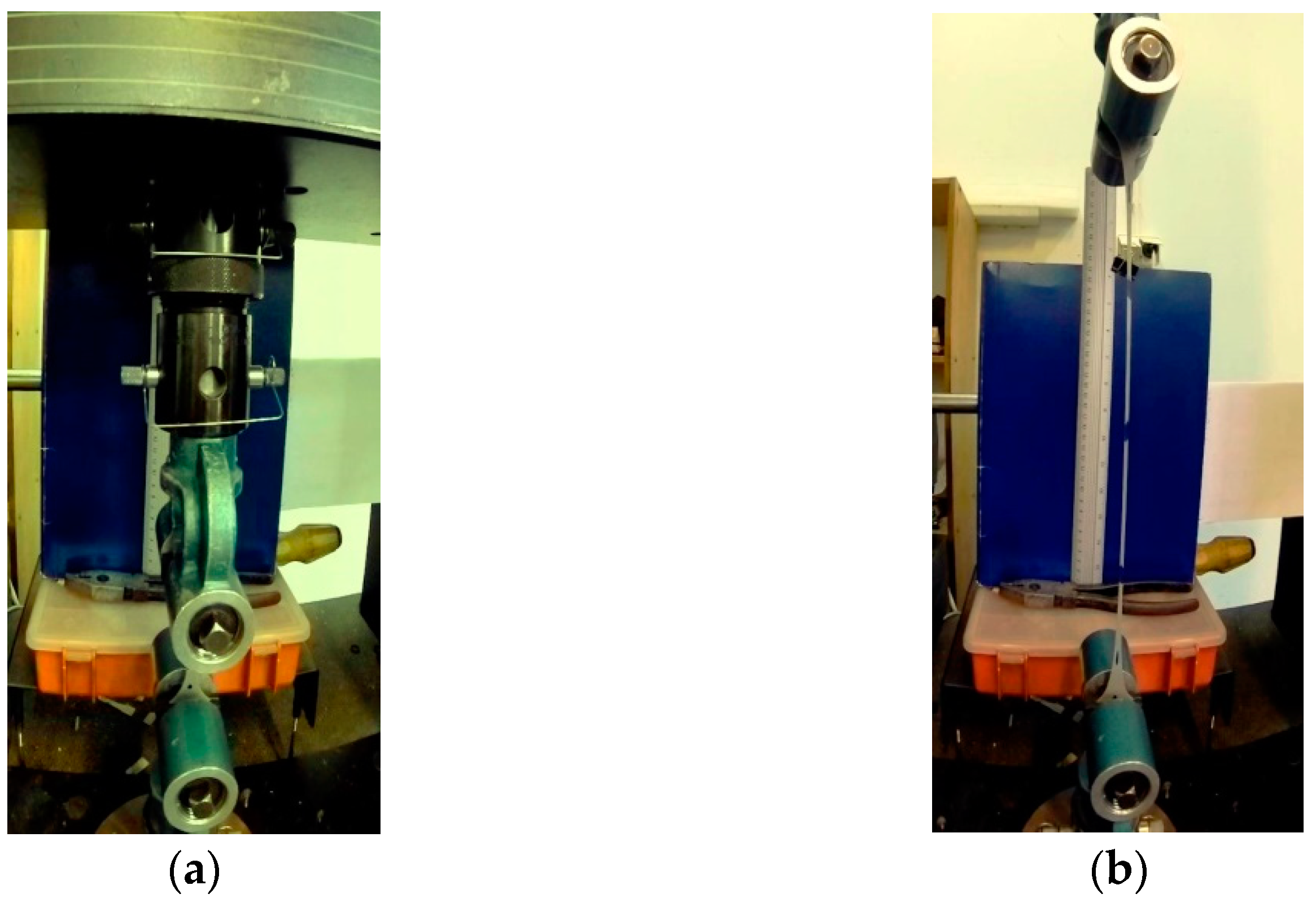
2.1.1. Polyurea
2.1.2. Concrete
2.1.3. Reinforcing Steel
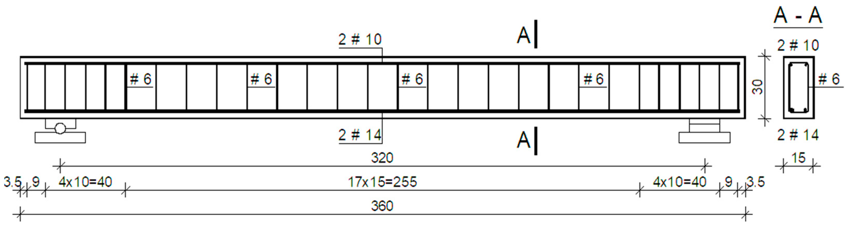
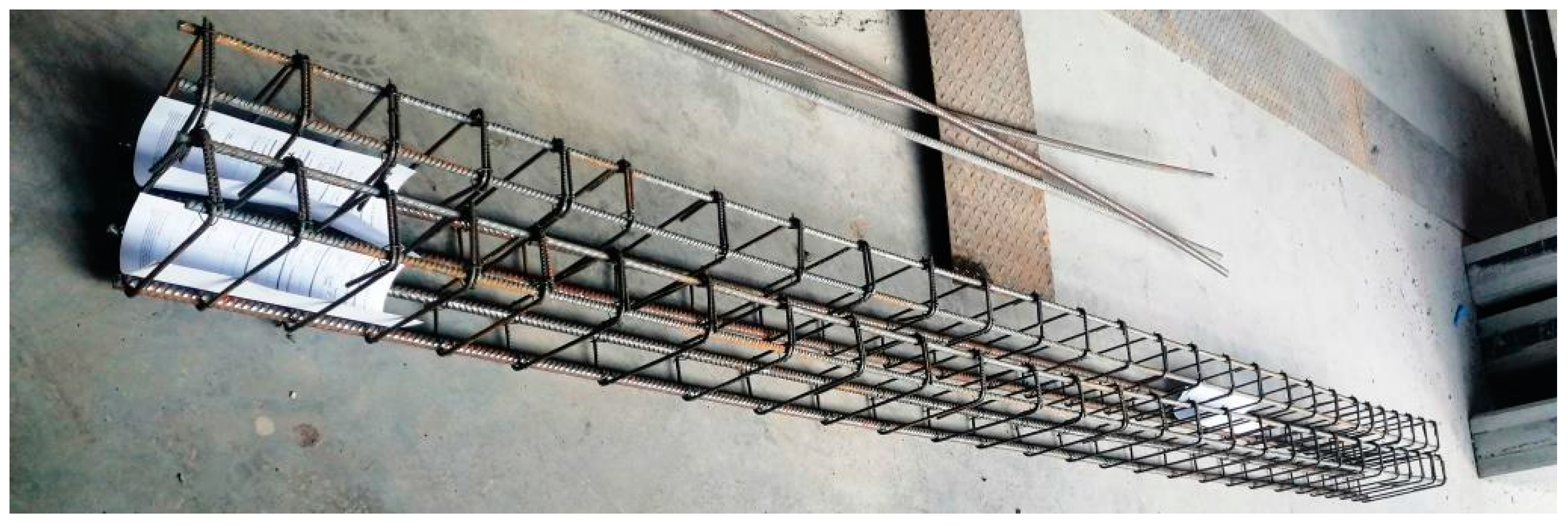
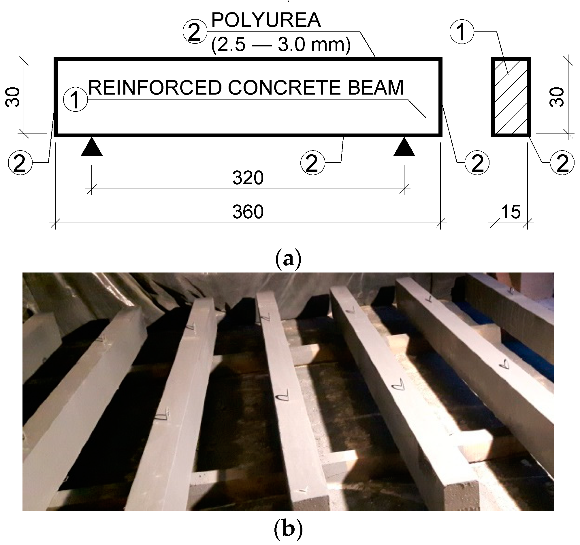
2.2. Reinforced Concrete Beams
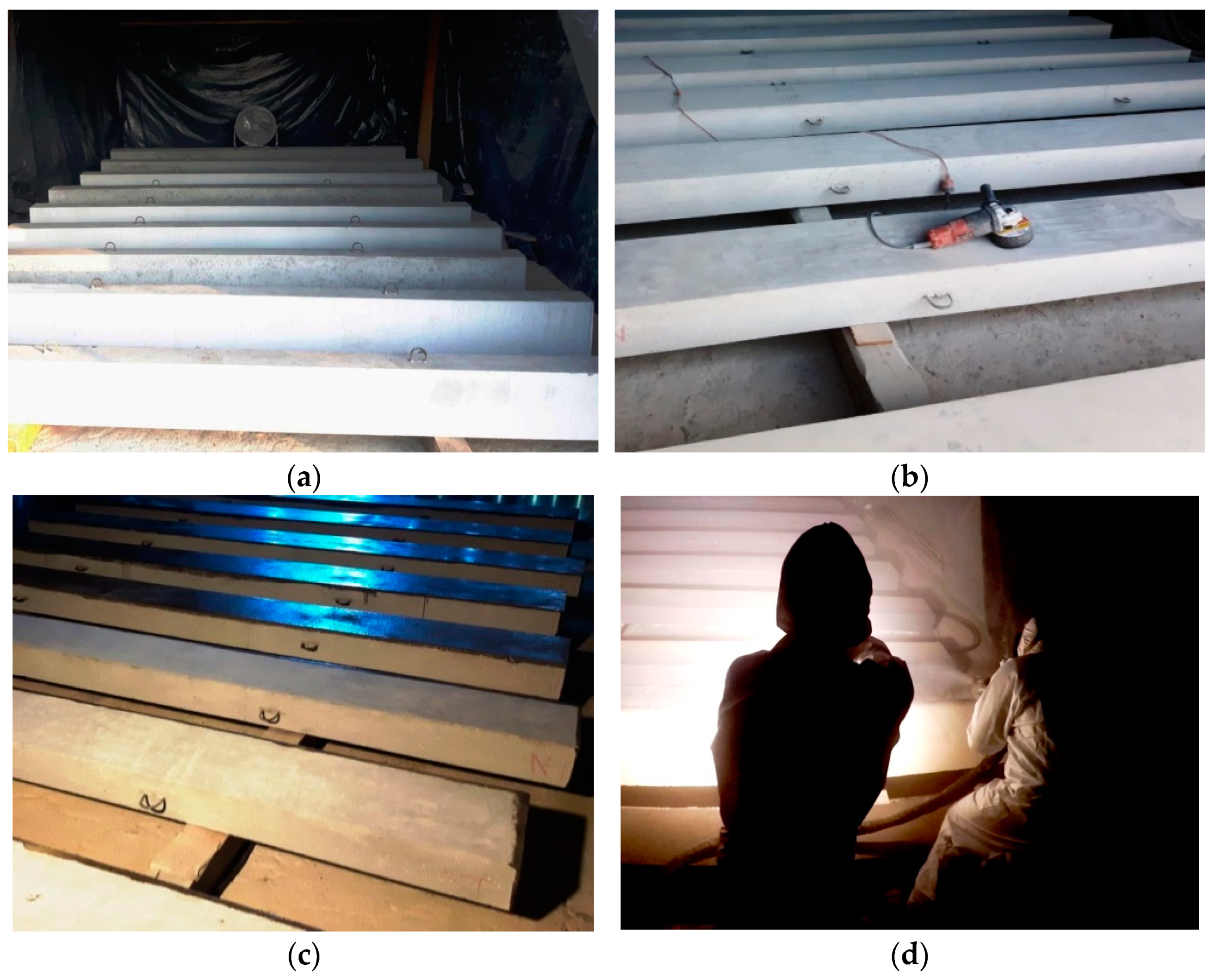
2.3. Beams with Polyurea Outer Layer
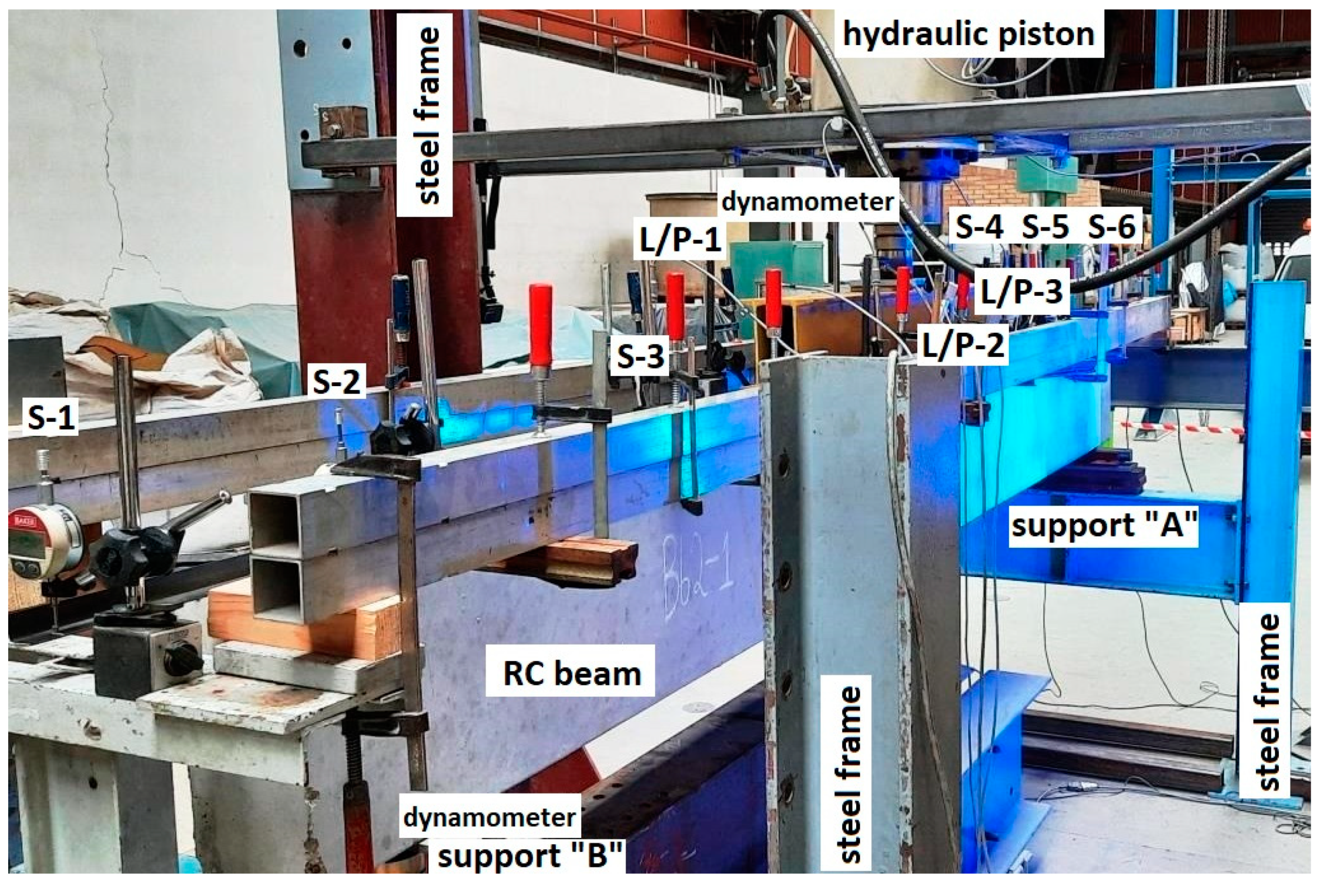
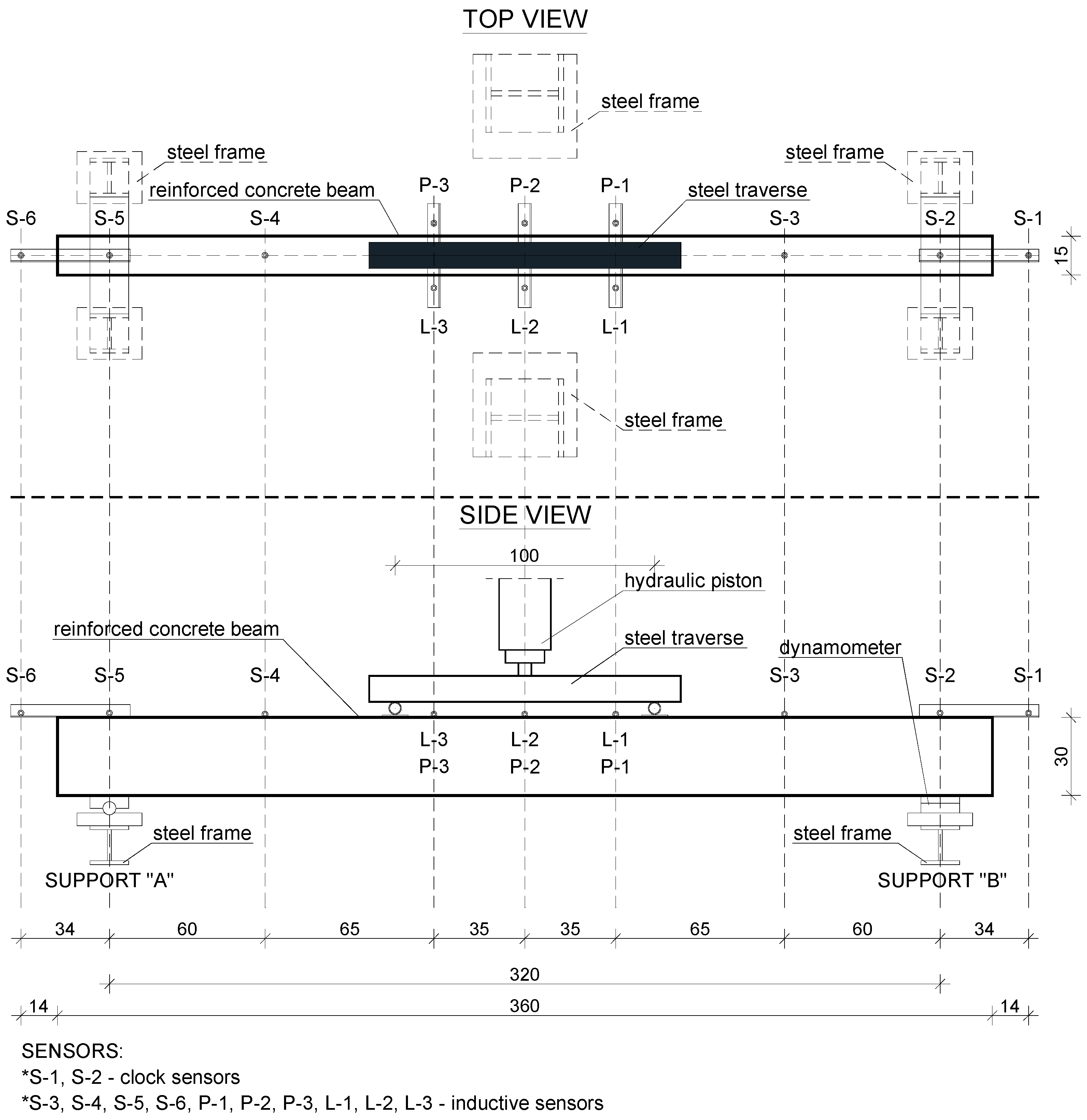
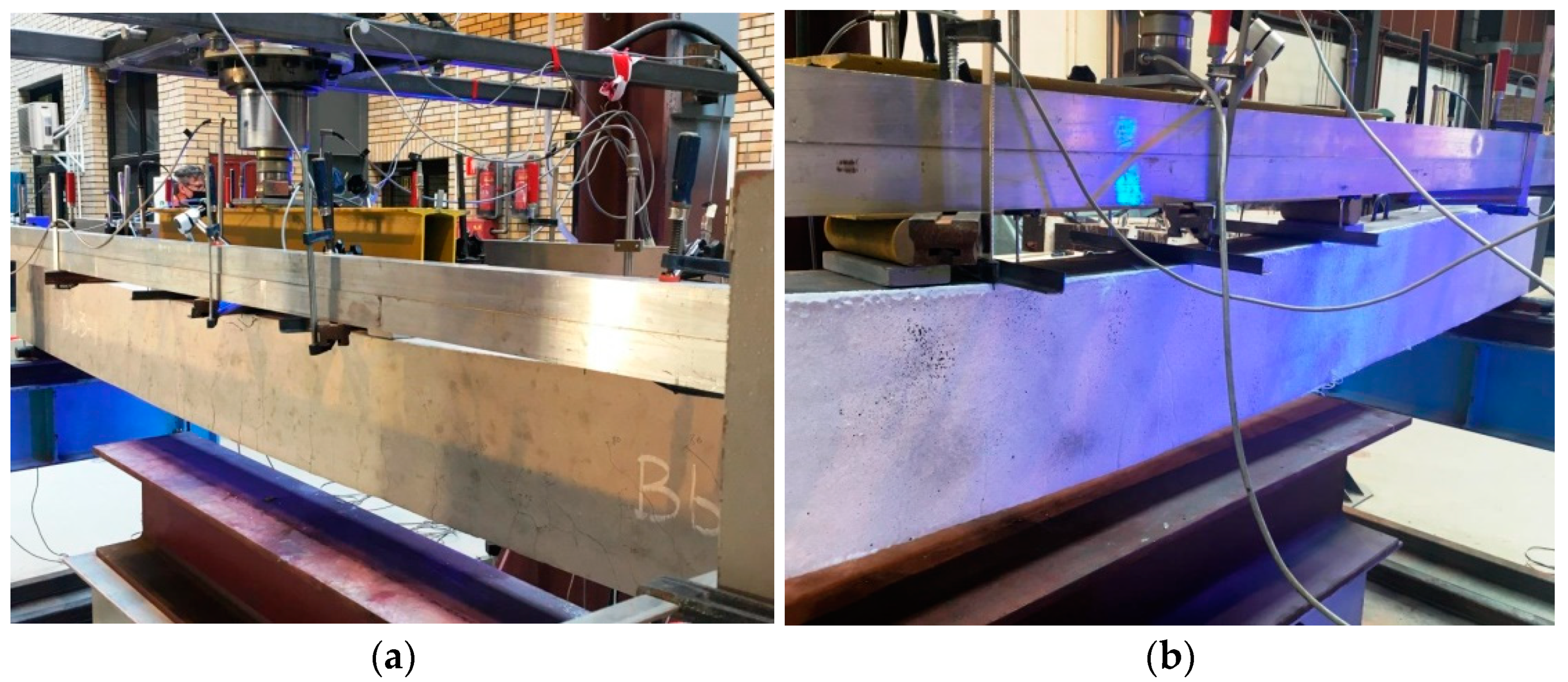
2.4. Test Stand
- A steel main frame of the test stand;
- A steel frame supporting the RC beams;
- A stand-alone steel frame supporting strain sensors;
- A hydraulic piston mounted to the upper part of the frame;
- A hydraulic pump to drive the piston;
- A workstation for data acquisition.
2.5. Measurements
3. Results
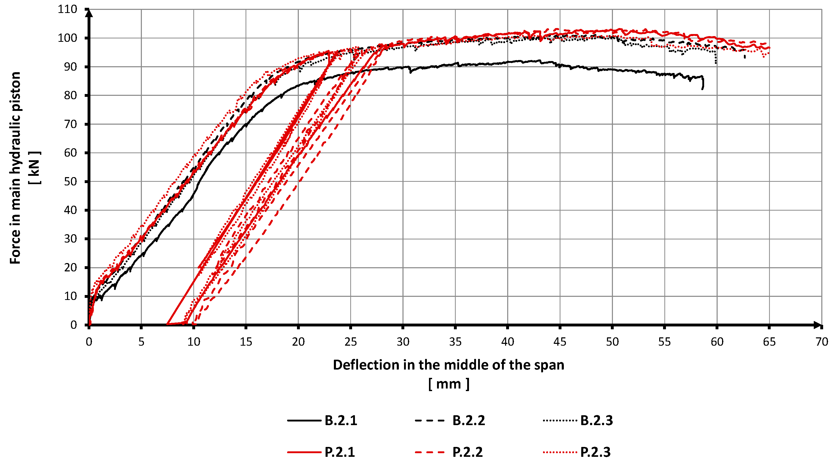
3.1. Bending Strength of RC Beams
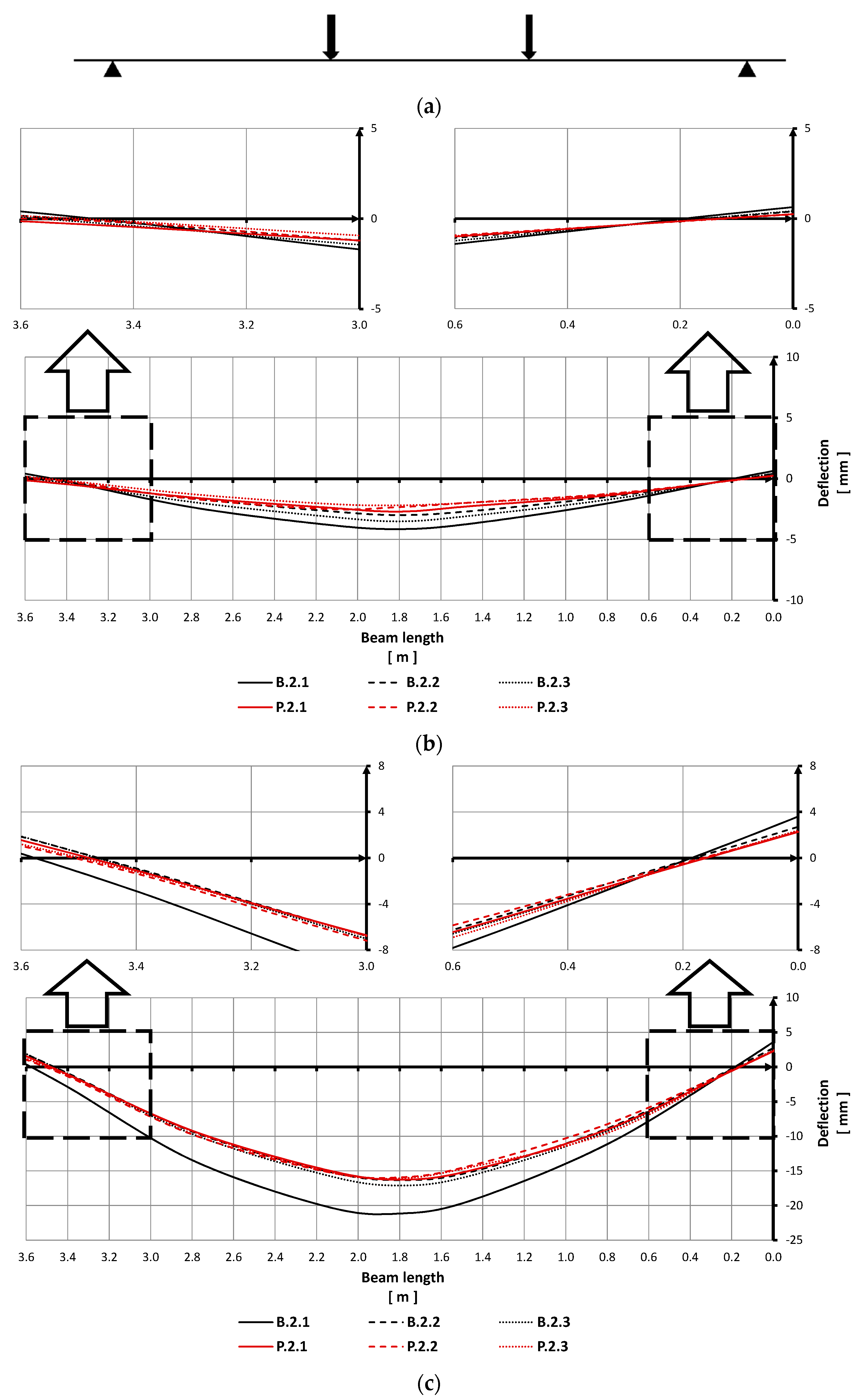
3.2. Displacements of the RC Beams
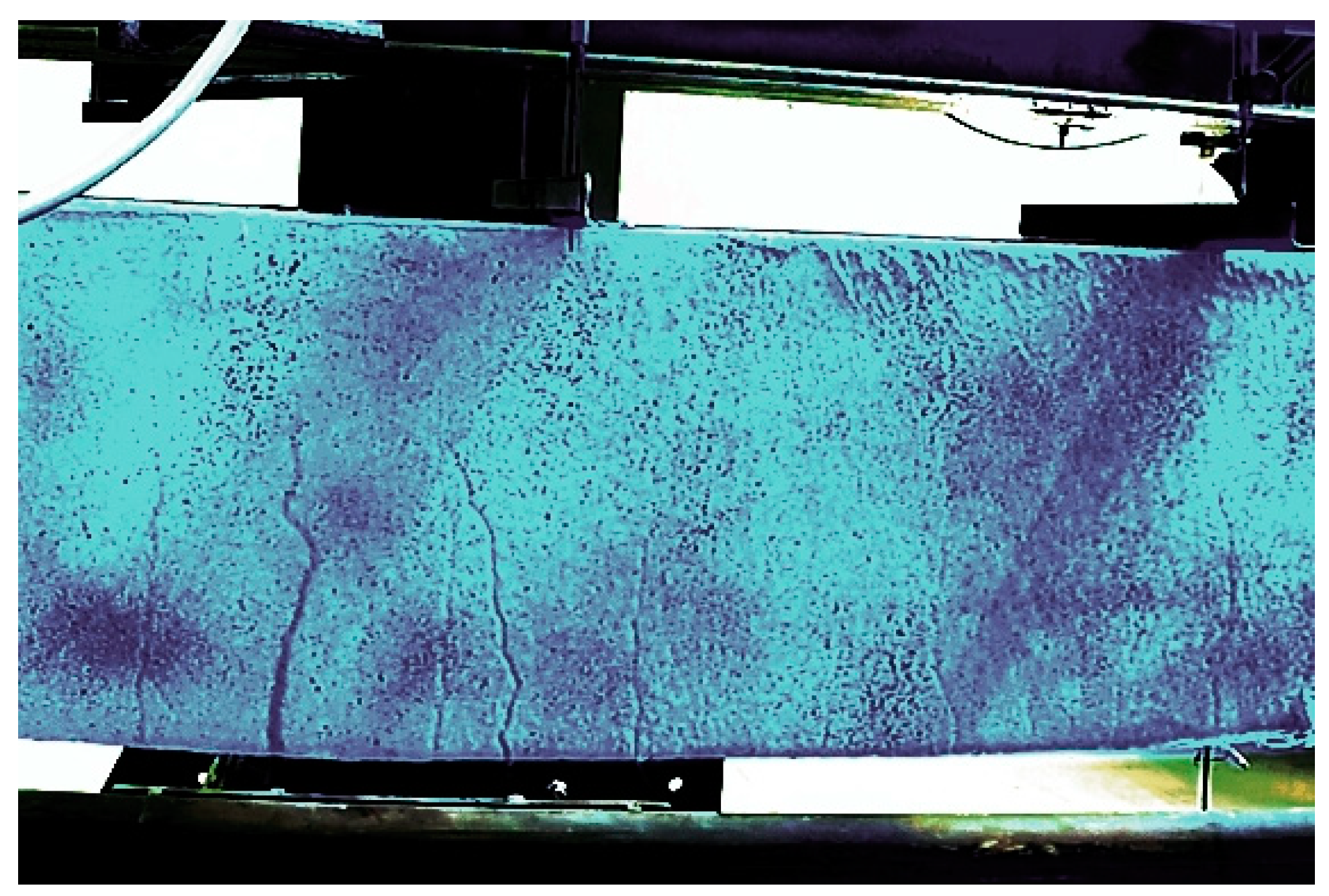
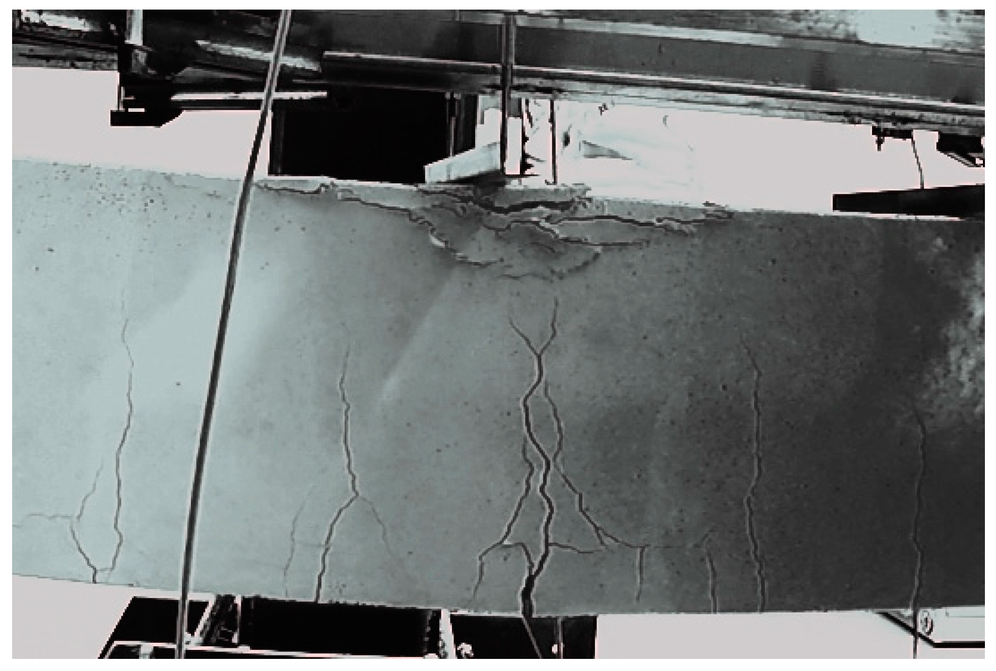
3.3. Component Cracking
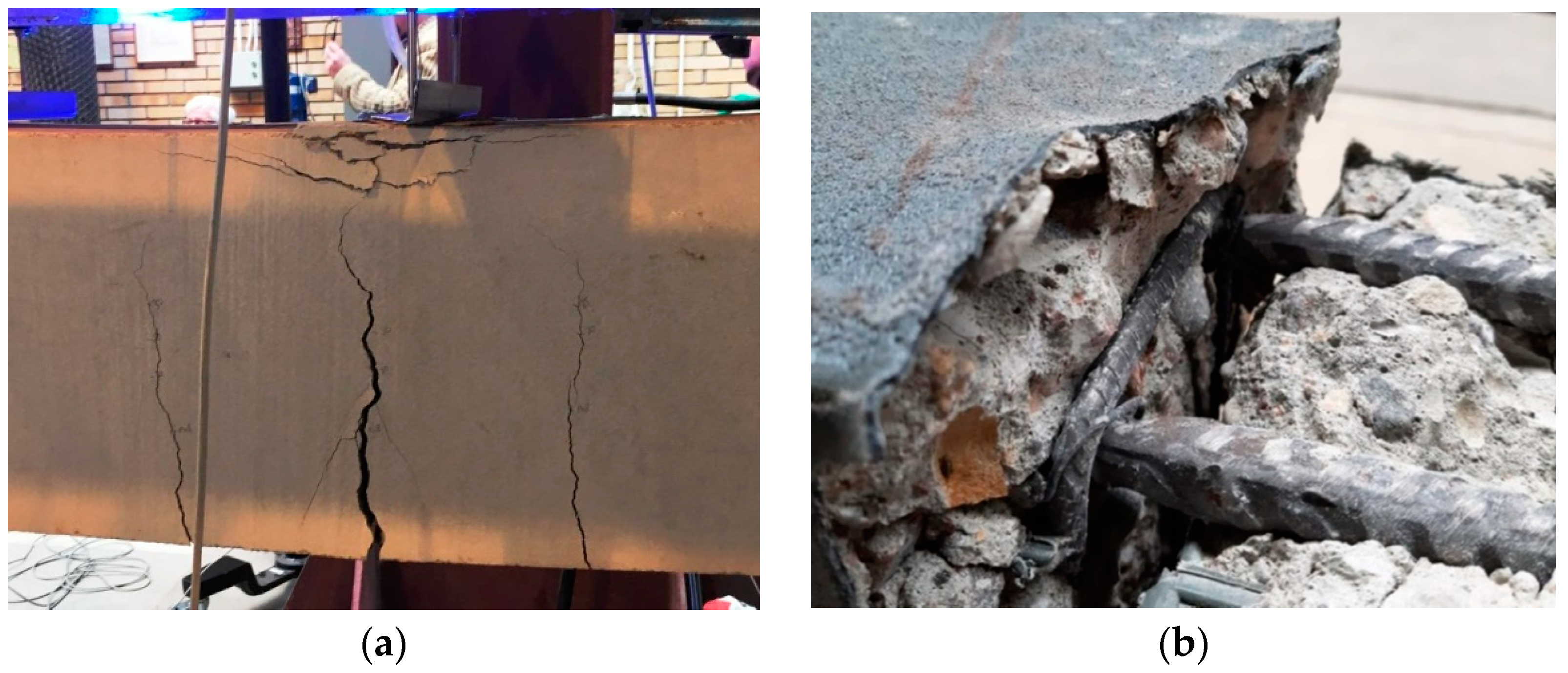
3.4. Failure Mechanisms
3.5. Serviceability Limit State (SLS)
- Stress limitation;
- Crack control;
- Deflection control.
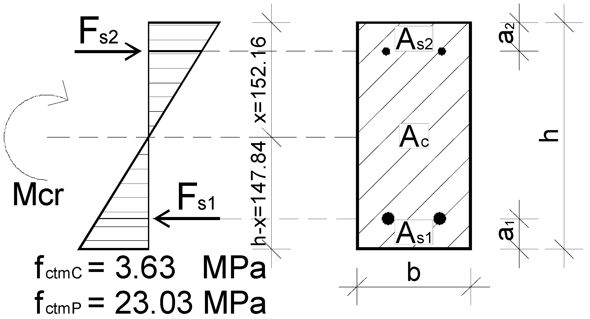
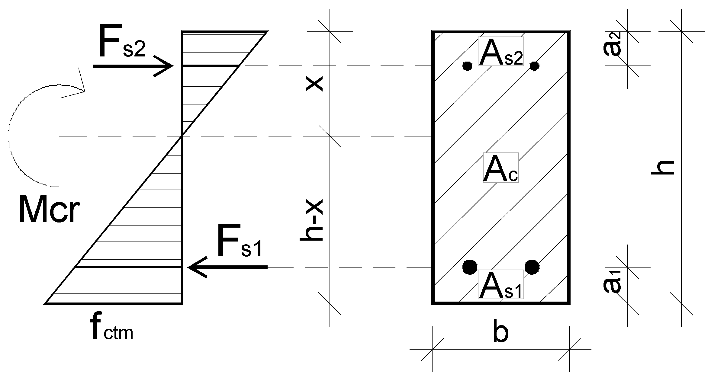
3.6. Description of Crack Formation in Polyurea-Coated Beams Based on Calculations
- Without taking the longitudinal reinforcement of beams into account, using formula:Mcr1 = fctm × Wc
- Taking the longitudinal reinforcement and the equivalent section into account, using formula:Mcr2 = fctm × Wcs
3.7. Cost Analysis of Polyurea Coating Application on Reinforced Concrete Elements
- Preparation of an existing concrete surface;
- Appropriate priming of the concrete surface;
- Applying the polyurea coating.
- From 75 EUR/m2 net for dry concrete surface without any defects and cracks;
- To 160 EUR/m2 net for wet concrete with deep defects and cracks.
4. Conclusions
- The application of polyurea coatings on the outer surface of RC beams increases their bending strength by 4.7%. The increase in the load-carrying capacity of the RC beams is insignificant in terms of the material and labor costs related to the membrane application;
- The tests showed that polyurea-coated RC beams can be safely subjected to loading and unloading (up to a value of 90%, which was used in the experimental research), which is the main difference between them and typical RC beams that cannot be safely subjected to this process;
- The impact of polyurea application on deflections of RC beams is visible at small load values, under normal operating conditions when the stiffness of an element mainly depends on the properties of concrete;
- The polyurea coating efficiently covers cracks and may protect the RC element during its exploitation against penetration by corrosive fluids (water, air, and chemical compounds); it brings considerable benefits because the coating may prolong the service life of the elements in such a manner;
- The tests revealed that elastic coating RC beams with a polyurea coating bonded well to concrete, providing full integrity of the elements throughout the whole loading process up to their complete failure;
- When the polyurea coating is applied, it creates considerable benefits when RC beams are used at the serviceability limit state because the coating covers cracks and prolongs the service life of the elements;
- The results of the experimental research and analytical calculations indicate that the polyurea coating can be used as a material designed to protect RC beams from cracking and the risk of exceeding their serviceability limit state due to cracking;
- The polyurea coating may improve the safety of people and RC structures as it replaces failure mechanisms with safer mechanisms and makes these elements integral and durable in imminent failure conditions.
Author Contributions
Funding
Institutional Review Board Statement
Informed Consent Statement
Data Availability Statement
Acknowledgments
Conflicts of Interest
References
- Ściślewski, Z. Protection of Reinforced Concrete Structures (in Polish); Arkady: Warsaw, Poland, 1999. [Google Scholar]
- Goszczyński, S. Cracking of Reinforced Concrete Beams (in Polish); Politechnika Świętokrzyska: Kielce, Poland, 1990. [Google Scholar]
- Kamińska, E.M.; Kotynia, R. Experimental Research on RC Beams Strengthened with CFRP Strips; Notebook No. 9; Lodz University of Technology: Łódź, Poland, 2000. [Google Scholar]
- Kotynia, R. FRP Composites for Flexular Strengthening of Concrete Structures. Theory, Testing, Des.; Lodz University of Technology Press: Łódź, Poland, 2019. [Google Scholar]
- Szafran, J.; Matusiak, A. Polyurea coating systems: Definition, research, applications. In Lightweight Structures in Civil Engineering—Contemporary Problems—Monograph from Scientific Conference of IASS Polish Chapters; University of Warmia and Mazury in Olsztyn: Olsztyn, Poland, 2016; pp. 103–110. [Google Scholar]
- Somarathna, H.M.C.C.; Raman, S.N.; Mohotti, D.; Mutalib, A.A.; Badri, K.H. The use of polyurethane for structural and infrastructural engineering applications: A state-of-the-art review. Constr. Build. Mater. 2018, 190, 995–1014. [Google Scholar] [CrossRef]
- Banera, J.; Maj, M.; Ubysz, A. Polyurea Coatings in Construction (in Polish); DTP: D-CONCEPT: Grupa MD: Poznań, Poland, 2017. [Google Scholar]
- Yi, J.; Boyce, M.C.; Lee, G.F.; Balizer, E. Large deformation rate-dependent stress-strain behavior of polyurea and polyurethanes. Polymer 2006, 47, 319–329. [Google Scholar] [CrossRef]
- Sarva, S.S.; Deschanel, S.; Boyce, M.C.; Chen, W. Stress-strain behavior of polyurea and a polyurethane from low to high strain rates. Polymer 2007, 48, 2208–2213. [Google Scholar] [CrossRef]
- Guo, H.; Guo, W.; Amirkhizi, A.V. Constitutive modeling of the tensile and compressive deformation behavior of polyurea over a wide range of strain rates. Constr. Build. Mater. 2017, 150, 851–859. [Google Scholar] [CrossRef]
- Raman, S.N.; Ngo, T.; Lu, J.; Mendis, P. Experminetal investigation on the tensile behavior of polyurea at high strain rates, Materials and Design. Mater. Des. 2013, 50, 124–129. [Google Scholar] [CrossRef]
- Mohotti, D.; Ali, M.; Ngo, T.; Lu, J.; Mendis, P. Strain rate dependent constitutive model for predicting the material behavior of polyurea under high strain rate tensile loading. Mater. Des. 2014, 53, 830–837. [Google Scholar] [CrossRef]
- Dukarski, W.; Krzyżanowski, P.; Gonsior, M.; Rykowska, I. Flame Retardancy Properties and Physicochemical Characteristics of Polyurea-Based Coatings Containing Flame Retardants Based on Aluminum Hydroxide, Resorcinol Bis (Diphenyl Phosphate), and Tris Chloropropyl Phosphate. Materials 2021, 14, 5168. [Google Scholar] [CrossRef] [PubMed]
- Arunkumar, T.; Ramachandran, S. Adhesion Behavior of Polyurea Coating on Mild Steel. Int. J. Appl. Eng. Res. 2015, 10, 1143–1149. [Google Scholar]
- Arunkumar, T. Theraml and Fire Retardant Behavior of Polyurea. Int. J. Appl. Eng. Res. 2015, 10, 10159–10162. [Google Scholar]
- Mariappan, T.; You, Z.; Hao, J.; Wilkie, C.A. Influence of oxidation state of phosphorus on the thermal and flammability of polyurea and epoxy resin. Eur. Polym. J. 2013, 49, 3171–3180. [Google Scholar] [CrossRef]
- Grujicic, M.; Bell, W.C.; Pandurangan, B.; He, T. Blast-wave impact-mitigation capability of polyurea when used as helmet suspension-pad material. Mater. Des. 2010, 31, 4050–4065. [Google Scholar] [CrossRef]
- Tekalur, S.A.; Shukla, A.; Shivakumar, K. Blast resistance of polyurea based layered composite materials. Compos. Struct. 2008, 84, 271–281. [Google Scholar] [CrossRef]
- Samiee, A.; Amirkhizi, A.V.; Nemat-Nasser, S. Numerical study of the effect of polyurea on the performance of steel plates under blast loads. Mech. Mater. 2013, 64, 1–10. [Google Scholar] [CrossRef]
- Ackland, K.; Anderson, C.; Ngo, T.D. Deformation of polyurea-coated steel plates under localised blast loading. Int. J. Impact Eng. 2013, 51, 13–22. [Google Scholar] [CrossRef] [Green Version]
- Mohotti, D.; Ngo, T.; Raman, S.N.; Mendis, P. Analytical and numerical investigation of polyurea layered aluminium plates subjected to high velocity projectile impact. Mater. Des. 2015, 82, 1–17. [Google Scholar] [CrossRef]
- Cai, L.; Al-Ostaz, A.; Li, X.; Fowler, C.; Cheng, A.H.D. Protection of steel railcar tank containing liquid chlorine from high speed impact by using polyhedral oligomeric silsesquioxane-enhanced polyurea. Int. J. Impact Eng. 2015, 75, 1–10. [Google Scholar] [CrossRef] [Green Version]
- Raman, S.N.; Jamil, M.; Ngo, T.; Mendis, P.; Pham, T. Retrofitting of RC Panels Subjected to Blast Effects using Elastomeric Polymer Coatings; Conference Paper; 5th International Conference on Concrete Repair: Belfast, UK, 2014. [Google Scholar]
- Iqbal, N.; Sharma, P.K.; Kumar, D.; Roy, P.K. Protective polyurea coatings for enhanced blast survivability of concreto. Constr. Build. Mater. 2018, 175, 682–690. [Google Scholar] [CrossRef]
- Davidson, J.S.; Porter, J.R.; Dinan, R.J.; Hammons, M.I.; Connell, J.D. Explosive Testing of Polymer Retrofit Masonry Walls. J. Perform. Constr. Facil. 2004, 18, 100–106. [Google Scholar] [CrossRef]
- Davidson, J.S.; Fisher, J.W.; Hammons, M.I.; Porter, J.R.; Dinan, R.J. Failure Mechanisms of Polymer-Reinforced Concrete Masonry Walls Subjected to Blast. J. Struct. Eng. 2005, 131, 1194–1205. [Google Scholar] [CrossRef]
- Duda, M.; Pach, J.; Lesiuk, G. Influence of Polyurea Composite Coating on Selected Mechanical Properties of AISI 304 Steel. Materials 2019, 12, 3137. [Google Scholar] [CrossRef] [PubMed] [Green Version]
- Che, K.; Lyu, P.; Wan, F.; Ma, M. Investigations on Aging Behavior and Mechanism of Polyurea Coating in Marine Atmosphere. Materials 2019, 12, 3636. [Google Scholar] [CrossRef] [PubMed] [Green Version]
- Pach, J.; Frączek, N.; Kaczmar, J. The Effects of Hybridisation of CompositesConsisting of Aramid, Carbon, and Hemp Fibres in a Quasi-Static Penetration Test. Materials 2020, 13, 4686. [Google Scholar] [CrossRef] [PubMed]
- Alldredge, D.J.; Gilbert, J.A.; Asce, M.; Toutanji, H.A.; Asce, F.; Lavin, T.; Balasubramanyam, M.S. Uplifit Capacity of Polyurea-Coated Light Frame Rafter to Top Plate Connections. J. Mater. Civ. Eng. 2012, 24, 1201–1210. [Google Scholar] [CrossRef]
- Feng, J.; Liao, L.; Chen, L.; Xiao, C.; Wang, S.; Li, H. Research on the formula of polyaspartic ester polyurea concrete coating and its application. Appl. Mech. Mater. 2013, 423, 1159–1163. [Google Scholar] [CrossRef]
- Ha, S.K.; Lee, H.K.; Kang, I.S. Structural behavior and performance of water pipes rehabilitated with a fast-setting polyurea-urethane lining. Tunn. Undergr. Space Technol. 2016, 52, 192–201. [Google Scholar] [CrossRef]
- Szafran, J.; Matusiak, A. Crushing strength of concrete rings with a polyurea reinforce system. Tunn. Undergr. Space Technol. 2020, 101, 1–10. [Google Scholar] [CrossRef]
- EN ISO 527:2012; Plastics. Determination of Tensile Properties. European Committee for Standardization (CEN): Brussels, Belgium, 2012.
- EN 12390-3:2019; Testing Hardened Concrete. Part 3: Compressive Strength of Test Specimens. European Committee for Standardization (CEN): Brussels, Belgium, 2019.
- EN 12390-6:2011; Testing Hardened Concrete. Part 6: Tensile Splitting Strength of Test Specimens. European Committee for Standardization (CEN): Brussels, Belgium, 2011.
- EN ISO 15630-1:2019; Steel for the Reinforcement and Prestressing of Concrete. Test Methods. Part 1: Reinforcing Bars, Rods and Wire. European Committee for Standardization (CEN): Brussels, Belgium, 2019.
- EN 1990:2004; Eurocode—Basis of Structural Design. European Committee for Standardization (CEN): Brussels, Belgium, 2004.
- EN 1992-1-1:2008; Eurocode 2. Design of Concrete Structures. Part 1-1: General Rules and Rules for Buildings. European Committee for Standardization (CEN): Brussels, Belgium, 2008.
- Słowik, M.; Błazik-Borowa, E. Cracking moment in bending concrete elements (in Polish). Maint. Reliab. 2004, 4, 50–53. [Google Scholar]
- Goszczyńska, B.; Tworzewska, J. Determining the scratch for the purposes of the analysis the results of the study of the process of formation and the development of cracks in reinforced concrete beams using the Aramis system (in Polish). Build. Rev. 2014, 12, 44–49. [Google Scholar]


| Test Speed | Number of Tests | Tensile Strength | Engineering Strain | Young’s Modulus |
|---|---|---|---|---|
| (mm/min) | (-) | (MPa) | (%) | (MPa) |
| 50 | 5 | 24.08 | 417 | 39.95 |
| 100 | 5 | 23.03 | 391 | 44.76 |
| Component | Amount per 1 m3 |
|---|---|
| (-) | (kg) |
| Sand (0–2 mm) | 610 |
| Gravel (2–8 mm) | 470 |
| Gravel (8–16 mm) | 690 |
| Cement CEM I 42.5 | 400 |
| Water | 100 |
| Admixtures | 3.3 |
| Specimen Number | Specimen Dimensions | Compression Strength | Tensile Splitting Strength | ||
|---|---|---|---|---|---|
| Result | Average | Result | Average | ||
| (-) | (-) | (MPa) | (MPa) | (MPa) | (MPa) |
| 01 | 150 × 150 × 150 | 71.01 | 72.35 | - | - |
| 02 | 150 × 150 × 150 | 72.56 | - | ||
| 03 | 150 × 150 × 150 | 73.49 | - | ||
| 04 | 150 × 150 × 150 | - | - | 3.54 | 3.63 |
| 05 | 150 × 150 × 150 | - | 3.83 | ||
| 06 | 150 × 150 × 150 | - | 3.50 | ||
| Rebar Diameter | Number of Tests | Lower Yield Stress | Tensile Strength | Young’s Modulus |
|---|---|---|---|---|
| (-) | (-) | (MPa) | (MPa) | (GPa) |
| #6 | 6 | 520.80 | 584.07 | 199.90 |
| #10 | 6 | 535.10 | 647.60 | 200.57 |
| #14 | 6 | 508.68 | 611.10 | 204.52 |
| Batch | Beam Designation | Average Coating Thickness | Load |
|---|---|---|---|
| (-) | (-) | (mm) | (-) |
| (1) beams used as control specimens | B.2.1 | - | bending test |
| B.2.2 | - | bending test | |
| B.2.3 | - | bending test | |
| (2) polyurea-coated beams | P.2.1 | 2.5–3.0 * | bending test |
| P.2.2 | 2.5–3.0 * | bending test | |
| P.2.3 | 2.5–3.0 * | bending test |
| Batch | Beam Designation | Breaking Force Exerted by the Piston * | Average Breaking Force | Breaking Force Gain | Beam Deflection for Fmax |
|---|---|---|---|---|---|
| (-) | (-) | (kN) | (kN) | (kN/%) | (mm) |
| beams used as control specimens | B.2.1 | 92.2 * | 97.9 | -/- | 43.0 |
| B.2.2 | 101.2 * | 50.4 | |||
| B.2.3 | 100.3 * | 48.6 | |||
| polyurea-coated beams | P.2.1 | 103.1 * | 102.5 | +4.6 kN(+4.7%) | 50.7 |
| P.2.2 | 103.2 * | 44.7 | |||
| P.2.3 | 101.2 * | 42.0 |
| Symbol | Es | Ecm | αe | Ac | αe × As1 | αe × As2 | Acs | Scs | x |
|---|---|---|---|---|---|---|---|---|---|
| Unit | (GPa) | (GPa) | (-) | (mm2) | (mm2) | (mm2) | (mm2) | (mm3) | (mm) |
| Value | 200 | 32 | 6.25 | 45,000 | 1924.25 | 981.75 | 47,906 | 7,289,497 | 152.16 |
| Comment | Standard value | Standard value | - | Cross-sectional area | Lower rebars 2#14 | Upper rebars 2#10 | Combined cross-section | Static moment | Height of compression area |
| Symbol | h-x | Ics | Wc | Wcs | fctm | Mcr1 | Mcr2 |
|---|---|---|---|---|---|---|---|
| Unit | (mm) | (mm4) | (mm3) | (mm3) | (MPa) | (kNm) | (kNm) |
| Uncoated beam | 147.84 | 374,172,588 | 2,250,000 | 2,530,972 | 3.63 | 8.17 | 9.19 |
| Coated beam | 147.84 | 374,172,588 | 2,250,000 | 2,530,972 | 23.03 | 51.82 | 58.29 |
| Comment | Height of the tension area | Moment of inertia of the combined section | Section modulus | Section modulus of the combined section | Tensile strength | Cracking moment according to Equation (2) | Cracking moment according to Equation (3) |
Publisher’s Note: MDPI stays neutral with regard to jurisdictional claims in published maps and institutional affiliations. |
© 2022 by the authors. Licensee MDPI, Basel, Switzerland. This article is an open access article distributed under the terms and conditions of the Creative Commons Attribution (CC BY) license (https://creativecommons.org/licenses/by/4.0/).
Share and Cite
Szafran, J.; Matusiak, A.; Rzeszut, K.; Jankowiak, I. Influence of Polyurea Coatings on Low-Longitudinal-Reinforcement-Ratio Reinforced Concrete Beams Subjected to Bending. Materials 2022, 15, 2652. https://doi.org/10.3390/ma15072652
Szafran J, Matusiak A, Rzeszut K, Jankowiak I. Influence of Polyurea Coatings on Low-Longitudinal-Reinforcement-Ratio Reinforced Concrete Beams Subjected to Bending. Materials. 2022; 15(7):2652. https://doi.org/10.3390/ma15072652
Chicago/Turabian StyleSzafran, Jacek, Artur Matusiak, Katarzyna Rzeszut, and Iwona Jankowiak. 2022. "Influence of Polyurea Coatings on Low-Longitudinal-Reinforcement-Ratio Reinforced Concrete Beams Subjected to Bending" Materials 15, no. 7: 2652. https://doi.org/10.3390/ma15072652
APA StyleSzafran, J., Matusiak, A., Rzeszut, K., & Jankowiak, I. (2022). Influence of Polyurea Coatings on Low-Longitudinal-Reinforcement-Ratio Reinforced Concrete Beams Subjected to Bending. Materials, 15(7), 2652. https://doi.org/10.3390/ma15072652