Abstract
The present work analyzed the microstructure, mechanical, and corrosion properties of a dissimilar activated tungsten inert gas (ATIG) welded 2205 duplex stainless-steel (2205 DSS) plate and AISI 316L austenitic stainless steel (316L ASS) and compared them to conventional dissimilar welded tungsten inert gas (TIG). The mixing design method is a tool used to establish the optimal combined flux to achieve a full-penetrated weld bead in one single pass. A microstructure study was carried out by scanning electron microscopy (SEM). The ATIG and TIG fusion zones revealed a matrix ferrite structure with intragranular austenite, Widmanstätten needles, allotriomorphic austenite at the grain boundaries, and plate-like precipitates free of deleterious phases such as sigma and chi phases or second austinite owing to the moderate heat input provided of 0.8 kJ/mm. Ferrite volume proportion measurements were carried out utilizing the areas image processing software. The average ferrite volume proportion attained 54% in the ATIG weld zone; however, it decreased to 47% for the TIG weld zone. The results showed that the optimal flux composed by 91% Mn2O3 and 9% Cr2O3 allowed a full penetrated weld to be obtained in one single pass. However, a double side weld is required for conventional TIG processes. The values of the tensile (599 Mpa), hardness (235 HV), and impact test (267 J/cm2) measurements of ATIG welds were close to those of conventional TIG welds. The elaborated flux did not degrade the mechanical properties of the joint; on the contrary, it reinforced the strength property. The width of the ATIG heat-affected zone was narrower than that of TIG welding by 2.6 times, ensuring fewer joint distortions. The potentiodynamic polarization test results showed a better electrochemical behavior for ASS 316L than with the weldment and the parent metal of DSS 2205.
1. Introduction
Nowadays, the industry has increasingly opted for high-performance materials and processes, which contribute to economic development. Dissimilar welding is a technical feat that meets the expectations of manufacturers. Dissimilar welding is beneficial on two aspects. First, it is beneficial from an economic point of view. Dissimilar welding allows the joining of expensive materials characterized by good corrosion resistance and good mechanical properties with another, cheaper material but of lower quality without altering the soundness of the joint, and it must meet the requirements of strength and safety of the structure being joined [1,2,3]. Secondly, a judicious choice of materials to be welded allows the targeted mechanical properties and corrosion resistance to be reached, needed for specific industry applications such as the nuclear industry, pipelines in desalination plants, and offshore oil and gas pipelines [4,5].
DSS grades are predominately used in marine fabrication industries such as the fabrication of ocean mining machinery, desalination plants, chemical tankers in ships, offshore concrete structures, pipelines, and oil and gas separators [6]. DSSs are usually selected where both high strength and corrosion resistance are required. DSS 2205 has been developed over the last two decades by metallurgists to obtain a stainless steel that is not only stronger than standard marine grade 316 but also offers much better corrosion resistance. The corrosion resistance of DSS 2205 is almost twice that of the ordinary 316. This is due to added levels of nickel, chromium, molybdenum, and nitrogen [7,8]. DSS 2205 is a combination of a ferritic phase with a BCC crystal structure and austenitic phase that crystallizes in FCC with a balance around 50%:50%. The ferrite structure assures high strength and withstands perfectly to stress corrosion cracking (SCC), while the austenite ensures good ductility and general corrosion resistance [9,10].
Austenitic stainless steels remain the most popular grades due to their unique combination of high weldability, high strengthening ability, high ductility, high toughness even at extra-low temperatures, and high corrosion resistance. The good weldability of austenitic stainless steel is affected by the hot cracking that occurs during the welding operation. This defect is ascribed to the presence of a susceptible chemical composition (low-melting-point constituents such as sulfur) and a high level of restraint or tensile stresses present in the weld [11].
The difficulties arising while welding dissimilar materials together are related to the fact that the larger the difference in melting point, the difference in linear expansion coefficient, and the thermal conductivity, the more difficult it is for the weld and the two base metals to meet the requirement of equal strength. To overcome these concerns, metal fillers are chosen related to materials to be joined [12,13], and when required, post-weld heat treatment (PWHT) is used [14] to reduce the mechanical properties to the targeted values. In other cases, the preheat is carried out to avoid any drawbacks in the weld, as in the work conducted by Ghosh et al., to achieve satisfactory joining between AISI 304 austenitic stainless steel to AISI 420 martensitic stainless steel [15].
The joining of austenitic stainless steel and duplex stainless steel is widespread in marine applications due to their combination of better corrosion resistance and good mechanical properties. However, problems such as the hot cracking tendency, the formation of a secondary austenite (γ2) phase, particularly in multiple weld passes [16,17], or the appearance of detrimental intermetallic phases such as sigma (σ), chi (χ), and chromium nitride (Cr2N) seriously affect the mechanical properties and corrosion resistance of the joint [11,18,19,20,21,22].
Tungsten Inert Gas (TIG) is the most widely used fusion welding process in industry due to its flexibility, on the one hand, and, on the other hand, a variety of materials can be welded using this technique. Unfortunately, this technique allows only 3 mm of depth to be reached in one single pass. In addition, TIG welding is very sensitive to microchemistry variations from cast to cast [23]. Activated Tungsten Inert Gas (ATIG) is an alternative method. The ATIG process was developed at the E.O. Paton Institute of Welding in Kiev in the 1960s. In ATIG welding, a thin layer of flux powder is deposited on edges to be joined. With this technique, 7 mm can be achieved in one single pass without filler metal or edge preparation. ATIG meets the requirements of manufacture in enhancing the productivity [24,25]. The improvement of penetration is related to the following mechanisms. The first mechanism is related to reverse Marangoni convection [26,27]. The second one is related to constriction of arc welding [28,29].
Many studies have investigated the dissimilar DSS 2205 and ASS 316L weld bead by testing different filler metals. For instance, Dhananjay et al. [30] tested different filler metals ER316L and ER309L. They showed in this study that the maximum average tensile strength of 548 MPa was obtained while ER316L filler metal was used compared to the value of 544 MPa when ER309L was tested. In another study, Verma et al. investigated the effects of different filler metals such as E2209, E309LMo, and E309L on dissimilar DSS 2205 and ASS 316L weld beads using multiple weld passes. The obtained tensile strength values were 554 MPa, 544 MPa, and 532 MPa for E2209, E309LMo, and E309L, respectively [31,32].
Limited works have been dedicated to establishing the effects of single flux powders on welds [33], and even fewer have been interested in the effect of combined powders on dissimilar DSS 2205 and ASS 316L weld beads. The novelty of this paper is in the use of the design of experiments mixing method tool to determine the best combination from the available oxide powders as an optimal flux in order to achieve a full penetrated dissimilar DSS 2205 and 316L ASS weld in a single pass without edge preparation, without altering mechanical properties and corrosion resistance of the joints, and without resorting to post-weld heat treatment (PWHT).
2. Materials and Methods
2.1. Material
The materials used in this study were the austenitic stainless-steel grade 316L and the duplex stainless-steel grade 2205 in rectangular plates of 6 mm thickness and 200 mm length × 100 mm width. The chemical composition of both stainless steels is given in Table 1. Table 2 depicts the oxides used and their physical properties.

Table 1.
Chemical composition (wt.%) of 316L and duplex grade 2205 stainless steels.
Table 2.
Oxides used and their physical properties.
2.2. Welding Procedure
ATIG welding was used to weld austenitic SS 316L and duplex SS 2205 in dissimilar butt joints. Before welding, the plates were cleaned with acetone. To eliminate humidity of the powder, it was heated separately in a furnace at 100 °C for 1 h. A thin layer of a mixed powder with methanol in the proportion of (1:1) made in a form of paste was applied using a brush on plain edges to be joined. The mean coating density of flux was about 4–5 mg/cm2. The joints were executed with a square butt weld design without edge preparation. Both plates were clamped with zero gap distance, as shown in Figure 1. The welding parameters used are reported in Table 3. The heat input recommendation is 0.5 to 2.5 kJ/mm, so the welding parameters chosen provided an acceptable range of moderate heat input of 0.8 kJ/mm.
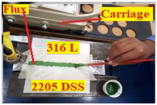
Figure 1.
The deposition of the mixed flux on the workpiece before ATIG welding.
Table 3.
Welding parameters used in this study.
After the ATIG welding, the samples were cut from the welded joints far from the welding starting point to be sure that the arc welding was stabilized, as shown in Figure 2.
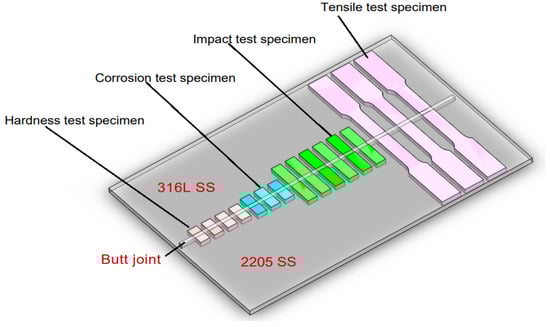
Figure 2.
Schematic drawing showing test specimens taken from the dissimilar ATIG welded DSS 2205 and 316L stainless steels for the different types of tests.
2.3. Design of Experiments Methodology
Design of Experiments (DOE) is considered one of the most essential statistical tools for designing high-quality experimental systems at a reduced cost. In this study, the mixing method was used and Minitab 17 software was the most appropriate tool for this purpose. In the first step, eight kinds of oxides (SiO2, TiO2, Fe2O3, Cr2O3, ZrO2, Mn2O3, V2O5, CoO3, MgO) were tested. Single oxides were deposited on both materials and welding operation was carried out. Among these eight oxides, three oxides candidates Cr2O3, Fe2O3, and Mn2O3 that gave the best depth of penetration and high ratio were selected to be used in the mixing design method. In the second step, based on the simplex lattice degree of four designs, nineteen combinations from the selected oxides were prepared. Finally, the optimal combination obtained was 91% Mn2O3 and 9% Cr2O3. Finally, a conventional TIG welding line and another with the ATIG technique were carried out.
2.4. Microstructure Investigation
The microstructural evolution of the fusion zone of both TIG and ATIG welds was investigated using a JEOL JSM-7600F scanning electronic microscope (SEM). Before investigation, the samples were polished up to 1200 grit fineness, followed by a cloth polishing to a 0.05 μm alumina surface finish. Then, samples were etched using Glyceregia solution (15cc HCl + 5cc HNO3 + 10cc glycerol). The areas image processing software from Microvision Instruments was used to measure the ferrite volume proportions.
2.5. Tensile Test
The tensile tests were carried out using a computer control electrohydraulic servo universal testing machine model WAW-300E at a cross head speed of 0.5 mm/min, a loading rate of 0.5 kN/s, and a strain rate of 1.6 × 10⁻⁴ s−1. The tensile tests were conducted for both dissimilar TIG, dissimilar ATIG, 316L/316L butt joints, and 2205 DSS/2205 DSS butt joints. For each sample category, three samples were prepared and tested. The tests were conducted according to the requirements of ASTM E8M-04, as shown in Figure 3.
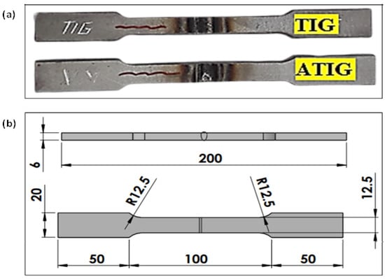
Figure 3.
Tensile test specimen (a); dimensions of specimen according to ASTM E8M-04 (b) (units in mm).
2.6. Hardness Test
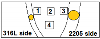
Micro Vickers hardness tests were performed by a digital hardness tester model HVS-50 with a standard load of 100 gf and dwell time of 10 s. The test was conducted according to ASTM E-384-99. The hardness line and tracks indentation are displayed in Figure 4. The measurements were performed on each sample with about 0.5 mm between two indentations. The hardness line measurements were far from the top surface by 2 mm.
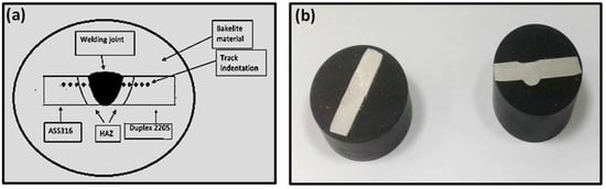
Figure 4.
Microhardness test specimens’ indentation locations (a) for ATIG samples (b) after hot mounting.
2.7. Impact Test
For impact tests, 3 samples for the dissimilar TIG welds and 3 samples for the dissimilar ATIG welds were prepared according to the ASTM E23 standard with the dimensions shown in Figure 5. A Charpy “V” notch impact testing machine was used for impact testing.
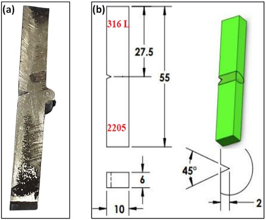
Figure 5.
Impact test specimen (a); dimensions of specimen (b) (units in mm).
2.8. Corrosion Behavior
Corrosion tests were carried out using a potentiodynamic polarization electrochemical system to obtain the main corrosion parameters such as corrosion potential (Ecorr), pitting potential (Ep), and corrosion current density (icorr) that can be used to evaluate the corrosion resistance. Electrochemical tests were performed using a potentiostat system of AUTOLAB-PGSTAT302N. Before testing, the samples were cut to the dimensions of 20 mm × 10 mm and grinded up to 1200 grit with SiC emery papers, taking into account six different regions of the welded joint: TIG weld metal, ATIG weld metal, TIG ASS 316L HAZ, ATIG ASS 316L HAZ, TIG DSS HAZ, and ATIG DSS HAZ, in addition to ASS 316L and DSS base metals. The data were collected after immersion in 3.5% NaCl solution for 1 h at room temperature. The tests were performed in the 3.5% NaCl solution at a scan rate of 1 mV/s. Platinum (Pt) was used as the auxiliary electrode, silver chloride (Ag/AgCl) was used as the reference electrode, and the sample was used as the working electrode.
3. Results and Discussions
3.1. Weld Bead Aspect
3.1.1. Selection of Candidate Oxides
The joints were executed with the butt weld design without edge preparation. Both plates were clamped with zero gap distance. Single oxide flux was deposited on plates to be welded with a total width of 10 mm. TIG weld and nine ATIG welds were carried out. The results in Table 4 clearly display that the three oxides candidates for the next steps are Cr2O3, Fe2O3, and Mn2O3 because they exhibit the highest penetrated weld beads and ratios (7.47 mm-1.66, 8.66 mm-1.68, and 7.02 mm-1.63), respectively.
Table 4.
Weld aspect of single oxides flux of dissimilar ATIG welds.
3.1.2. Mixture Contour of Plot
According to the mixture method, simplex lattice degree four is the most appropriate for our experiments. We prepared nineteen compositions with different proportions of oxides selected, which were Fe2O3, Cr2O3, and Mn2O3. Table 5 shows the chemical compositions of the nineteen combinations and the related results of depths and ratios.
Table 5.
Dimensions of depth (D) and R (ratio) of ATIG weld beads.
The compositions of the flux were the input data, and both the depth (D) and the ratio (R) were the output response. To visualize the relationships between the components in a three-component mixture, the triangular coordinate systems were used. Figure 6 shows the contour plots for depth, and the ratio that generated based on the experimental results is shown in Figure 7.
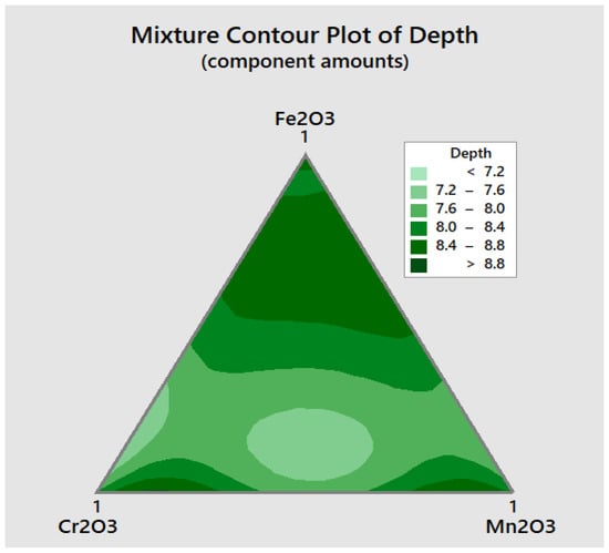
Figure 6.
Mixture contour plot for the depth D of penetration.
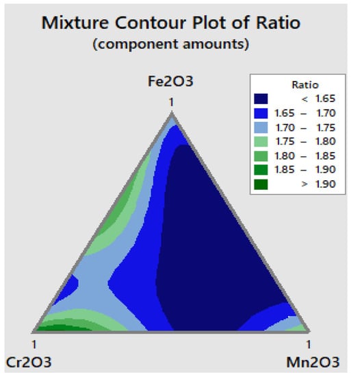
Figure 7.
Mixture contour plot for ratio R.
From the mixture contour plot for depth D, three main regions can be observed, where the maximum depth can be attained. The first region is close to manganese oxide, the second region is close to chromium oxide, and the third one is far from the base of the triangle, as can be seen in Figure 6.
The mixture contour plot for flux ratio shows three main regions where the maximum depth can be achieved. The first region is close to manganese oxide, the second region is close to chromium oxide, and the third one is close to the triangle rib (Cr2O3–Fe2O3) from the base of the triangle, as shown in Figure 7.
The optimizer module available in Minitab 17 software waws used to find the optimal composition. Figure 8 shows the optimization plot that indicates how the variables of Fe2O3, Cr2O3, and Mn2O3 affect the predicted responses in terms of both penetration depth D and flux ratio R. It should be noted that the numbers at the top of the columns show the current variable settings and the high and low variables settings in the data. Two points for each cell represent the two levels of the categorial variable. If the level for each variable is equal to 1, it indicates a high level, and if it is equal to 0, it indicates a low level. The level between the high and low levels represents the best mixing flux composition, which is 91% Mn2O3 + 9% Cr2O3 + 0% Fe2O3.
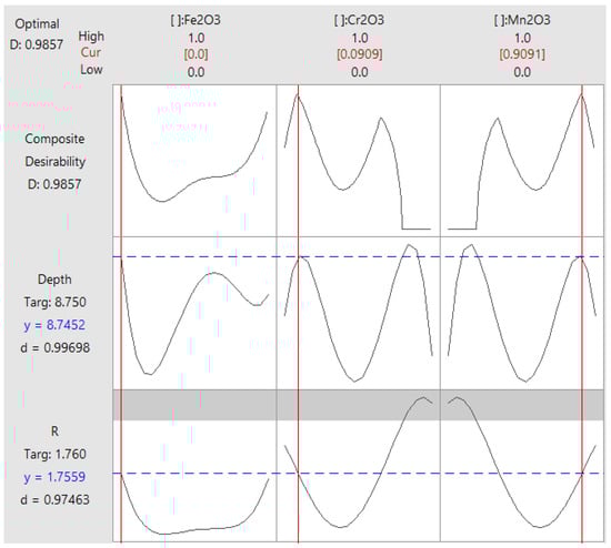
Figure 8.
Optimization plot for depth D and ratio R.
Figure 8 shows the predicted response “y” and the individual desirability score “d” for both the depth and ratio for the current variable settings, as can be seen from the first column. Hence, the predicted response for the depth is y = 8.75 mm and the corresponding desirability is 0.99. The predicted response for the ratio is y = 1.76 and the corresponding desirability is 0.97. Thus, the overall composite desirability becomes 0.98. This indicates that the variables achieve favorable results for all responses, and it means that both responses are within acceptable limits.
3.1.3. Validation Test
The third step is about the validation weld line. Accordingly, the combination flux was prepared. ATIG dissimilar welding was executed using the optimal composition with the same conventional parameters of the TIG weld. The transverse cross-sections of the weld beads were investigated using an optical microscope CAROLINA (CAROLINA, Burlington, NC, USA). Based on that investigation, the obtained penetration depth (D) is 8.93 mm and the bead face width (W) is 8.87 mm for ATIG welding, which lead to an aspect ratio D/W of 1.94. It can be noted that the depth is increased by about 2.4 times and the ratio is enhanced by about 5.7 times compared to the conventional TIG welding. Better yet, the measured depth and ratio are higher than the predicted values of 8.75 mm and 1.75, respectively. The depth bead profile data of the conventional TIG weldments and of ATIG with the optimal flux are listed in Table 6. Figure 9 presents macrographs for the cross-section of the TIG welded bead and those of the ATIG with the optimal flux. It is clearly observed that the bead has a full penetration after ATIG welding.
Table 6.
Dissimilar weldment bead profiles data of TIG (conventional) and ATIG (optimal flux).
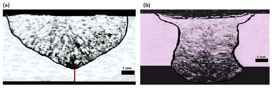
Figure 9.
Transverse optical macrographs of the dissimilar welded beads using TIG (a) and ATIG (b).
3.2. Microstructure Assessment
Based on a WRC-1992 diagram before welding, the DSS Creq/Nieq ratio equals 2.63. DSS solidifies in ferrite mode. The DSS microstructure consists of both ferrite (α) and austenite (γ) phases in almost equal proportion. However, the ASS 316L Creq/Nieq ratio equaling 1.56 solidifying in austenite-ferrite mode leads to the formation of austenite (γ) with the formation of strip δ ferrite.
The weld bead microstructure shown in Figure 10a for the ATIG weld and Figure 10b for the TIG weld indicates the existence of delta ferrite (δ) and austenite (γ) phases. First, the solidification of molten metal results in the formation of ferrite matrix immediately after solidification, and then the nucleation of austenite phases starts upon a further cooling cycle. In the weld region, three different austenite phases’ morphologies are found. They are a thin grain boundary austenite, an elongated Widmanstätten austenite structure, and an intragranular austenite phase. Transverse profile ferrite volume proportions of the 2205/316L stainless-steel dissimilar welded joint are depicted in Table 7 and shown in Figure 11. They reveal an evolution of ferrite volume proportions seen from the HAZ of the 316L ASS to the 2205 DSS HAZ. The average ferrite volume proportion in the ATIG weld zone reaches 57%, greater than that of the TIG weld zone of 47%.
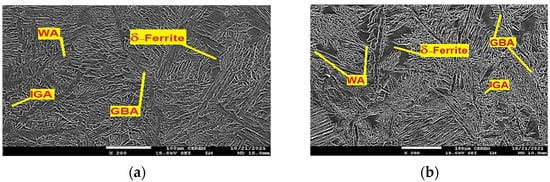
Figure 10.
TIG weld zone (a) and ATIG weld zone (b) (500×).
Table 7.
Ferrite volume proportions % in weld zone and HAZ for ATIG and TIG weldments.
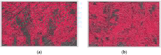
Figure 11.
Ferrite proportion measurements of dissimilar TIG (a) and ATIG (b) welds (500×).
The ATIG weld with optimal flux increases the arc voltage, and the amount of heat input per unit length in a weld is also increased. The energy density of the source leads to high heat input. However, the arc weld of TIG welding without flux has a lower energy density and, therefore, in this case, a lower heat input in comparison with ATIG. TIG welding associated with low heat input is characterized by a relatively rapid cooling rate in comparison to that of the ATIG weld [34]. In the ATIG weld zone, a slow cooling rate allows for more transformation of ferrite to different types of austenite (GBA (ferrite grain boundaries), Widmanstätten, IGA (Intragranular grain austenite)). However, the TIG weld specimen executed using double passes receives more heat transferred to the joint and, consequently, more formation of austenite is expected, as well as higher ferrite volume proportions that influence the mechanical properties and reinforce the strength and hardness properties [35].
For the TIG weld, the HAZ width of about 300–500 μm is observed on the duplex steel side, as shown in Figure 12a. The HAZ microstructure consists of lamellar austenite precipitates located mainly on the equiaxial high ferrite grain boundaries and, in a minor amount, inside the ferrite grains with the presence of small proportions of Widmanstätten side plates off the ferrite grain boundary. The ferrite volume proportion is up 69% in that zone, which is significantly higher in comparison to the parent material of 2205 DSS. The wide HAZ of about 120–160 μm is observed on the 316L ASS side, as shown in Figure 12b. The microstructure consists of strips of ferrite precipitates that surround austenite grains. In the 316L ASS HAZ side, the ferrite volume proportion is up to 8%, as listed in Table 7. The width of the DSS HAZ side is higher than that of 316L HAZ by 2.5–3.1 times. This result is in good concordance with that obtained in the study of Topolska et al. [36].
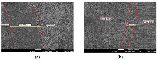
Figure 12.
TIG HAZ DSS side (a) and 316L side (b) (×100).
In the ATIG weld, the HAZ of about 120–200 μm is observed on the duplex steel side, as shown in Figure 13a. Moreover, the microstructure consists of continuous networks of austenite at the ferrite grain boundaries (GBA) and also the austenite phase formed as Widmanstätten (WA), in addition to intragranular austenite within the ferrite grains (IGA). The ferrite volume proportions in this zone reaches 63%, which is significantly higher compared to the parent material of 2205 DSS.
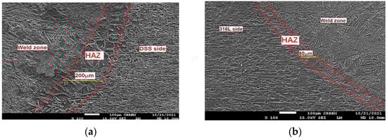
Figure 13.
ATIG HAZ DSS side (a) and 316L side (b) (×100).
The wide zone of about 60–80 μm is observed on the HAZ 316L side, as shown in Figure 13b. The ATIG HAZ DSS side is wider than that of the TIG HAZ 316L side by 2 to 2.5 times. The microstructure consists of δ ferrite precipitates in a matrix of austenite grains. The ferrite volume proportions in this zone decrease to 6.9%. We notice that the TIG HAZ is wider than that of ATIG HAZ for both sides, respectively. This effect can be ascribed to the fact that the heat provided to the ATIG weld bead is more concentrated owing to constriction of the ATIG arc weld than that of the TIG weld [37].
On the other hand, the HAZ of the DSS side for both ATIG and TIG welds is wider than that of the 316L side, owing to a higher thermal conductivity of 2205 DSS compared to that of 316L. This result is in good agreement with the results obtained by Taheri et al. [35].
3.3. SEM/EDS Analysis
Referring to Figure 14a, we notice an increase in the Cr element at the fusion border of the 316L side in the TIG weld. This observation clearly indicates the presence of more δ ferrite phase in this region compared to the ATIG weld shown in Figure 14b.

Figure 14.
SEM-EDS micrographs and data obtained for TIG (a) and ATIG (b) ASS 316L side fusion border.
We also remark, in the latter region, the presence of the Mo element close to that of 316L parent metal that suggests that the ATIG weld could withstand aggressive environments.
Cr, Ni, Mn, and Mo element contents labeled in Figure 15b of the ATIG DSS 2205 side fusion border are close to the parent metal, leading to more ferrite phase formation. However, in Figure 15a, we remark an increase in the austenite phase, promoting elements such as Ni and Mn, which indicates the formation of more austenite phase compared to ATIG DSS 2205.
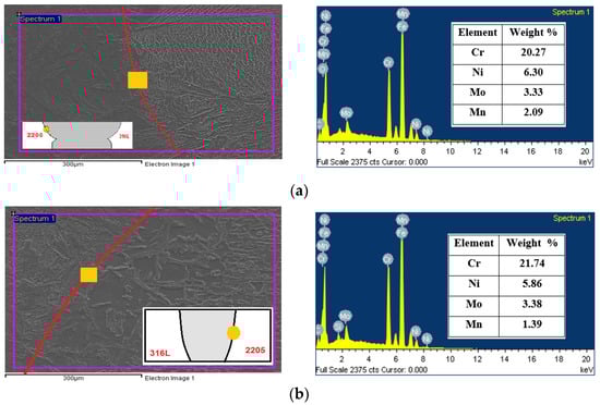
Figure 15.
SEM-EDS micrographs and data obtained for TIG (a) and ATIG (b) DSS 2205 side fusion border.
3.4. Tensile Test
The average value of the ultimate tensile strength (UTS) of the ATIG dissimilar weld is 599 MPa, which is close to that of conventional TIG welding (594 MPa), as shown in Table 8.
Table 8.
Measurements of tensile strength and standard deviation of TIG welds and ATIG welds with optimal flux.
We notice that the fractures for ATIG and TIG dissimilar welds are localized at the base metal, precisely at the ASS 316L base metal and outside the weld zone, as shown in Figure 16. This may be ascribed to differences in the chemical composition that promote the dual-phase nature and a stronger solid solution strengthening mechanism as mentioned in some works [38,39]; hence, a reduction in ductility of these zones must be expected. The DSS BM has a strength superior by 205 MPa of that of 316L BM. Indeed, the duplex material contains the ferrite phase, which allows a material with greater UTS.
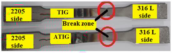
Figure 16.
Specimens of the tensile testing after the test.
The fracture faces in both cases show similar ductile elongated large dimples, attesting the reduction in ductility of 316L austenitic stainless steel with cleavage facets, as shown in Figure 17.
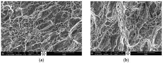
Figure 17.
Fracture surface of TIG (a) and ATIG (b) dissimilar 316L- 2205 DSS at break zone (×1000).
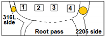
The obtained strength does not denote the strength of the weld joint. The weld joint strength is higher than the value obtained in TIG and ATIG welds. The TIG specimen fractured at 594 MPa is about 96% of the 316L base metal strength. In addition, the ATIG specimen breaks at 599 MPA, which is about 97% of the 316L base metal strength. The test shall be accepted because it meets the requirements. The values of the standard deviations (σ) are less than 5 MPa, which attests the accuracy and reliability of the obtained results. Figure 18 displays the tensile test curves of the welds, which are similar TIG 316L (#1), similar DSS 2205 (#2), dissimilar ATIG (#3), and dissimilar TIG (#4). The used flux does not negatively affect the tensile property of the weld.
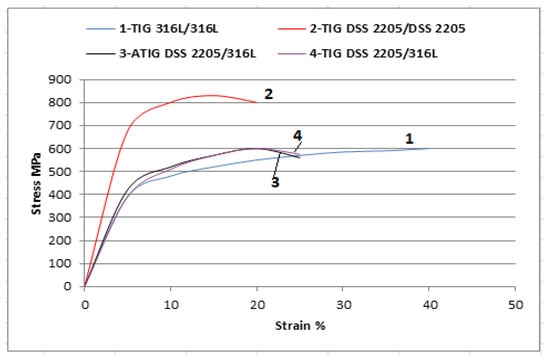
Figure 18.
Stress vs. strain curves of the different weldments.
3.5. Hardness Test
Variations in the Vickers micro hardness as a function of the distance from the DSS 2205 to the 316L SS in the sample are shown in Figure 19 for both ATIG and TIG welds. The hardness at the weld zone of the ATIG weld (average 235 HV) shows little variation compared to that of the TIG weld (237 HV), which is more constant.
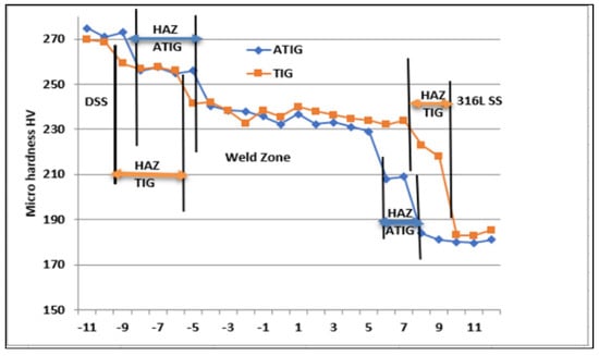
Figure 19.
Micro hardness profiles across the centerline of dissimilar ATIG and dissimilar TIG welds.
The average hardness value in the ATIG fusion region (235 HV) is roughly equal to that of the TIG fusion zone (237 HV) weld. The highest value of hardness (242 HV) is located at the TIG weld zone at the nearest point of DSS/WZ. The standard deviations are less than 4 HV, which indicates good hardness homogeneities in the joints, as shown in Table 9.
Table 9.
Measurements of hardness and standard deviation of TIG and ATIG (optimal flux) at FZ.
The results collected in Table 10 are related to the micro hardness tests at the HAZ of the weldments. The average hardness value is found to be greater at the HAZ of the DSS 2205 side (257.5–257 HV) compared to that of the 316L side (222–210 HV) for dissimilar TIG and dissimilar ATIG welds. On the other hand, the standard deviations are less than 4 HV, which attests the small disparities in the obtained hardness values between the maximum and the minimum values.
Table 10.
Measurements of hardness and standard deviation of TIG and ATIG with the optimal flux at HAZ.
3.6. Impact Test
The impact tests were carried out only in the fusion zones of ATIG and TIG welds. The obtained experimental results are displayed in Figure 20. The average energy absorbed in the fusion zone in the case of the ATIG 2205 DSS/316L SS dissimilar weld (267 J/cm2) is slightly lower than that of the dissimilar TIG weld (275 J/cm2). The dissimilar ATIG and dissimilar TIG welds have almost the same ability to withstand shocks. The standard deviations are less than 8 J/cm2. Figure 21 shows the broken TIG and ATIG dissimilar weld specimens after the impact test.
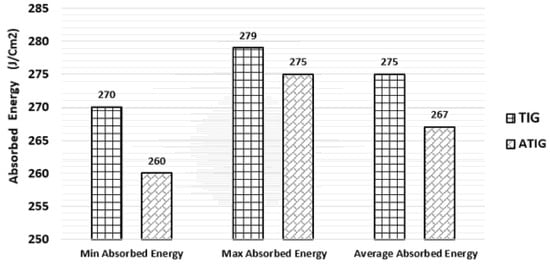
Figure 20.
Measurements of energy absorbed of TIG and ATIG (optimal flux) at fusion zone for dissimilar 2205 DSS/316L SS weld.
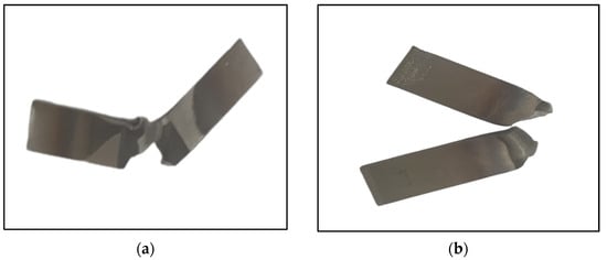
Figure 21.
Specimens of TIG (a) and ATIG (b) after the impact testing.
The SEM fractography represented in Figure 22a belongs to the TIG weld. It indicates multiple and fine dimples with ductile dimple tearing resulting from the coalescence of micro voids, which confirms the ductile fracture mode during the impact test. Figure 22b shows the formation of a network of multiple homogenous dimples without voids, which characterizes the ductile fracture for the ATIG weld. The absorbed energy of the ATIG weld is close to that of the TIG weld, which ensures that the elaborated flux does not adversely affect the resistance of the ATIG weld during sudden loads.
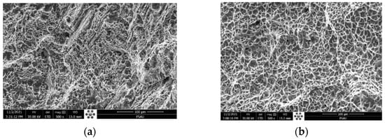
Figure 22.
SEM fractography of dissimilar TIG (a) and ATIG (b) weldments in the FZ (×500).
3.7. Corrosion Behavior
The potentiodynamic polarization curves of the base metals, heat-affected zones, and weld metals in the 3.5% NaCl solution at room temperature are illustrated in Figure 23 and Figure 24. The corrosion current (Icorr), the corrosion potentials (Ecorr), and the pitting potentials (Epit) of the different samples are summarized in Table 11. It can be seen that the weld metals display a passive behavior similar to those of the ASS 316L and DSS 2205 base metals. However, the anodic behavior of the weld metal in TIG and ATIG are notably different from the ASS 316L and DSS base metals, both in terms of the corrosion potential (Ecorr) and current density, which can be attributed to the difference in the chemical composition and microstructure. The parent metal of ASS 316L exhibits a minimum corrosion rate when compared to DSS 2205, TIG, and ATIG weldment. ASS-BM exhibits a corrosion potential of −927 mV versus SCE, which is more notable than the potentials observed for DSS-BM, as well as weld metals TIG and ATIG (−974 mV, −1050, and −1032 mV), respectively. On the other hand, Table 11 shows the values of icorr for both the TIG weld zone (54.5 μA/cm2) and ATIG weld zone (54.1 μA/cm2), and those for TIG and ATIG HAZ in both ASS and DSS regions are higher than those of the base metals (24.4 μA/cm2 and 29.8 μA/cm2 for ASS and DSS, respectively). This indicates that protection of the passive film formed in these regions is less than that of the base metals. This can be explained by the deformation resulting from the microstructural changes and the residual stresses generated by the welding thermal cycle [40].
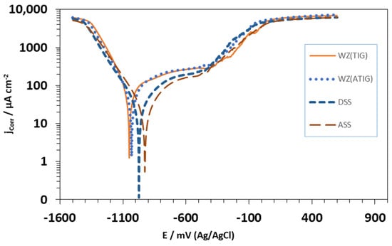
Figure 23.
Curve of potentiodynamic polarization for electrolyte 3.5% NaCl solution obtained under the areas of TIG and ATIG weld metal and base metals.
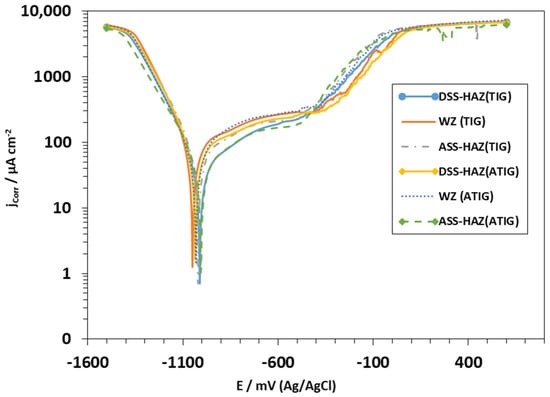
Figure 24.
Curve of potentiodynamic polarization for electrolyte 3.5% NaCl solution obtained under the areas of HAZ of the AISI 316L alloy and HAZ of the AISI 2205 alloy for both TIG and ATIG, and again for the weld metal (kept as reference).
Table 11.
Electrochemical data of ASS, DSS base metals, TIG, and ATIG weld metals obtained from potentiodynamic polarization studies in 3.5 M NaCl solution.
Furthermore, it is also noted that TIG and ATIG weld metals, as well as TIG and ATIG HAZ in DSS region, have values of pitting potentials higher than those of the base metals ASS (−455 mVSCE) and DSS (−434 mVSCE), which means that these regions have better performance with respect to localized corrosion.
On the other hand, it is again observed that TIG and ATIG HAZ in ASS regions display low values of Epit in the solution of 3.5% NaCl, indicating that these regions of the welded joint are more susceptible to localized pitting corrosion.
4. Conclusions
In this work, a comparison between dissimilar ATIG and dissimilar TIG welds of DSS grade 2205 steel and ASS grade 316L was carried out. Having investigated the mechanical properties, microstructure, and corrosion behavior of the welds, the following main conclusions can be drawn:
- −
- The mixing method design is a key tool to elaborate the flux composed by 91% Mn2O3 and 9% Cr2O3. The ATIG weld carried out with the optimal flux achieves a full penetration weld without edge preparation or the use of a filler metal. The depth in the ATIG weld is greater than that of conventional TIG by 2.4 times.
- −
- The volume proportion of ferrite, based on areas image analysis, shows that the average ferrite volume proportion in the ATIG weld zone reaches 57%, greater than that of the TIG weld zone (47%). Moreover, the welds are free of deleterious phases such as sigma phases owing to the moderate heat provided to the weld pool of 0.8 kJ/mm.
- −
- In the ATIG weld, the 2205 DSS HAZ width is 200 μm, while in the 316L ASS one, HAZ is about 80 μm. In the same way, in the TIG weld, the 2205 DSS HAZ is very wide, attaining 500 μm, while in the 316L ASS one, the HAZ width is 160 μm. The HAZ of 2205 DSS sides contains more ferrite phase, while the 316L sides are mainly composed by the austenite phase with sparse bands of δ ferrite.
- −
- The tensile strength value of the ATIG weld metal reaches 599 MPa, which is closer to that of the TIG weld (594 MPa). The hardness measurements at the weld zones shows close results for both TIG and ATIG, with average values of 237 HV and 235, respectively. The average energy absorbed during the toughness impact test reaches 267 J/cm2 for the ATIG weld compared to 275 J/cm2 for the TIG weld. The elaborated optimal flux has no negative effect on the mechanical properties of the welds.
- −
- The weld metals display passive behavior similar to those of ASS 316L and DSS base metal.
- −
- The parent metal of ASS 316L was subjected to a minimum corrosion rate when compared to DSS 2205, TIG, and ATIG weldment.
- −
- Moreover, TIG and ATIG HAZ in ASS regions display low values of Epit, indicating that these regions of the welded joint are very susceptible to localized pitting corrosion.
Author Contributions
Conceptualization, K.T. and A.C.H.; methodology, K.T. and R.D.; software, K.T., A.B. and A.C.H.; validation, K.T., R.D., A.O. and A.C.H.; formal analysis, K.T. and M.M.Z.A.; investigation, K.T., R.D., A.O., H.S.A. and A.C.H.; resources, A.I.; data curation, K.T.; writing—original draft preparation, K.T.; writing—review and editing, K.T., R.D., A.O. and M.M.Z.A.; visualization, K.T. and M.M.Z.A.; supervision, K.T. All authors have read and agreed to the published version of the manuscript.
Funding
This research received no external funding.
Institutional Review Board Statement
Not applicable.
Informed Consent Statement
Not applicable.
Data Availability Statement
The data used to support the findings of this study are included within the article.
Conflicts of Interest
The authors declare no conflict of interest.
References
- Kumar, N.; Kumar, A.; Gupta, A.; Gaikwad, A.D.; Khatirkar, R.K. Gas Tungsten Arc Welding of 316 L Austenitic Stainless Steel with UNS S32205 Duplex Stainless Steel. Trans. Indian Inst. Met. 2018, 71, 361–372. [Google Scholar] [CrossRef]
- Wang, S.; Ma, Q.; Li, Y. Characterization of Microstructure, Mechanical Properties and Corrosion Resistance of Dissimilar Welded Joint between 2205 Duplex Stainless Steel and 16MnR. Mater. Des. 2011, 32, 831–837. [Google Scholar] [CrossRef]
- Ghosh, N.; Pal, P.K.; Nandi, G. GMAW dissimilar welding of AISI 409 ferritic stainless steel to AISI 316 L austenitic stainless steel by using AISI 308 filler wire. Eng. Sci. Technol. Int. J. 2017, 20, 1334–1341. [Google Scholar]
- Labanowski, J. Stress Corrosion Cracking Susceptibility of Dissimilar Stainless Steels Welded Joints. J. Achiev. Mater. Manuf. Eng. 2007, 20, 255–258. [Google Scholar]
- Rahmani, M.; Eghlimi, A.; Shamanian, M. Evaluation of microstructure and mechanical properties in dissimilar austenitic/super duplex stainless steel joint. J. Mater. Eng. Perform. 2014, 23, 3745–3753. [Google Scholar] [CrossRef]
- Gunn, R.N. Duplex Stainless Steels: Microstructure, Properties and Applications, 3rd ed.; Abington Publishing, Woodhead Publishing Ltd.: Cambridge, UK, 1997. [Google Scholar]
- Charles, J. Composition and properties of duplex stainless steels. Weld. World 1995, 36, 89–97. [Google Scholar]
- Labanowski, J. Duplex stainless steels—New material for chemical industry. Appar. Chem. Eng. 1997, 36, 3–10. [Google Scholar]
- Baldev, R.; Shankar, V.; Bhaduri, A.K. Welding Technology for Engineers; Narosa Publishing House: New Delhi, India, 2009; p. 55. [Google Scholar]
- Ma, L.; Hu, S.; Shen, J. Microstructure, Properties and Weldability of Duplex Stainless Steel 2101. J. Mater. Eng. Perform. 2017, 26, 250–257. [Google Scholar] [CrossRef]
- Lippold, J.C.; Kotecki, D.J. Welding Metallurgy and Weldability of Stainless Steels; Wiley Publications: Hoboken, NJ, USA, 2005. [Google Scholar]
- Zhang, J.; Huang, Y.; Fan, D.; Zhao, J.; Huang, J.; Yu, X.; Liu, S. Microstructure and performances of dissimilar joints between 12Cr2Mo1R steel and 06Cr18Ni11Ti austenitic stainless steel joined by AA-TIG welding. J. Manuf. Process. 2020, 60, 96–106. [Google Scholar] [CrossRef]
- Kumar, A.; Pandey, C. Autogenous laser-welded dissimilar joint of ferritic/martensitic P92 steel and Inconel 617 alloy: Mechanism, microstructure, and mechanical properties. Arch. Civ. Mech. Eng. 2022, 22, 39. [Google Scholar] [CrossRef]
- Rogalski, G.; Świerczyńska, A.; Landowski, M.; Fydrych, D. Mechanical and Microstructural Characterization of TIG Welded Dissimilar Joints between 304L Austenitic Stainless Steel and Incoloy 800HT Nickel Alloy. Metals 2020, 10, 559. [Google Scholar] [CrossRef]
- Ghosh, A.; Pal, P.K. Corrosion behaviour of dissimilar TIG welded austenitic stainless steel AISI 304 and martensitic stainless steel AISI 420. Indian J. Eng. Mater. 2020, 27, 665–669. [Google Scholar]
- Geng, S.; Sun, J.; Guo, L.; Wang, H. Evolution of microstructure and corrosion behavior in 2205 duplex stainless steel GTA-welding joint. J. Manuf. Process. 2015, 19, 32–37. [Google Scholar] [CrossRef]
- Ramirez, A.J. The Relationship between Chromium Nitride and Secondary Austenite Precipitation in Duplex Stainless Steels. Metall. Mater. Trans. A 2003, 34, 1575–1597. [Google Scholar] [CrossRef]
- Kısasöz, A.; Tümer, M.; Karaaslan, A. Effect of Multipass Welding on Microstructural and Mechanical Properties of AISI 2205 Duplex Stainless Steel. In Proceedings of the 3rd Iron and Steel Symposium (UDCS’17), Karabuk, Turkey, 3–5 April 2017. [Google Scholar]
- Dubie, S.M.; Cieslak, J. Sigma-phase in Fe-Cr and Fe-V alloy systems and its physical properties. Crit. Rev. Solid State Mater. 2011, 36, 191–208. [Google Scholar] [CrossRef] [Green Version]
- Escriba, D.M.; Materna-Morris, E.; Plaut, R.L.; Padilha, A.F. Chiphase precipitation in a duplex stainless steel. Mater. Charact. 2009, 60, 1214–1219. [Google Scholar] [CrossRef]
- Hsieh, C.C.; Wu, W. Overview of Intermetallic Sigma Phase Precipitation in Stainless Steels. Int. Sch. Res. Not. 2012, 2012, 1–16. [Google Scholar] [CrossRef]
- Jimenez, J.A.; Carsi, M.; Ruano, O.A. Characterization of a δ/γ duplex stainless steel. J. Mater. Sci. 2000, 35, 907–915. [Google Scholar] [CrossRef]
- Vidyarthy, R.S.; Dwivedi, D.K. Activating flux tungsten inert gas welding for enhanced weld penetration. J. Manuf. Process. 2016, 22, 211–228. [Google Scholar] [CrossRef]
- Touileb, K.; Ouis, A.; Djoudjou, R.; Hedhibi, A.; Alrobei, H.; Albaijan, I.; Alzahrani, B.; Sherif, E.; Abdo, H. Effects of ATIG Welding on Weld Shape, Mechanical Properties and Corrosion Resistance of 430 Ferritic Stainless Steel Alloy. Metals 2020, 10, 404. [Google Scholar] [CrossRef] [Green Version]
- Kulkarni, A.; Dwivedi, D.K.; Vasudevan, M. Effect of oxide fluxes on activated TIG welding of AISI 316L austenitic stainless steel. Mater. Today Proc. 2019, 18, 4695–4702. [Google Scholar] [CrossRef]
- Vijay, S.J.; Mohanasundaram, S.; Ramkumar, P.; Kim, H.G.; Tugirumubano, A.; Go, S.H. Experimental investigations on activated-TIG welding of Inconel 625 and AISI 304 alloys. In Advances in Materials and Manufacturing Engineering; Springer: Singapore, 2020; pp. 311–317. [Google Scholar]
- Alrobei, H.; Touileb, K.; Djoudjou, R.; Ouis, A.; Hedhibi, A.; AlBaijan, I.; Malik, R.; Sherif, E. Mechanical and Corrosion Resistant Properties of ATIG welded 2205 Duplex Stainless-Steel via different fluxes. J. Mech. Sci. Technol. 2021, 35, 5469–5476. [Google Scholar] [CrossRef]
- Aniekan, E.I.; Ikechukwu, O.; Ikpe, E.E. Effects of arc voltage and welding current on the arc length of tungsten inert gas welding (TIG). Int. J. Eng. Technol. 2017, 3, 213–221. [Google Scholar]
- Jaypuria, S.; Mahapatra, T.R.; Sahoo, S.; Jaypuria, O. Effect of arc length trim and adaptive pulsed-MIG process parameters on bead profile of stainless steel with synergic power source. Mater. Today Proc. 2020, 26, 787–795. [Google Scholar] [CrossRef]
- Tumu, D.P.; Subramani, P.; Kumar, K.G.; Manikandan, M.; Mohan, C.G.; Arivazhagan, N.; Rajan, D.N. Investigation on microstructure and tensile properties of dissimilar weld joints between AISI 316l and duplex 2205 stainless steel. In IOP Conference Series: Materials Science and Engineering; IOP Publishing: Bristol, UK, 2018; Volume 402, p. 7. [Google Scholar]
- Verma, J.; Taiwade, R.V. Effect of Austenitic and Austeno-Ferritic Electrodes on 2205 Duplex and 316L Austenitic Stainless Steel Dissimilar Welds. J. Mater. Eng. Perform. 2016, 25, 4706–4717. [Google Scholar] [CrossRef]
- Verma, J.; Taiwade, R.V.; Khatirkar, R.K.; Kumar, A. A Comparative Study on the Effect of Electrode on Microstructure and Mechanical Properties of Dissimilar Welds of 2205 Austeno-Ferritic and 316L Austenitic Stainless Steel. Mater. Trans. 2016, 57, 494–500. [Google Scholar] [CrossRef] [Green Version]
- Satelkar, D.S.; Jogi, B.F.; Thorat, S.B.; Chavan, A.A. Activated pulsed-tungsten inert gas welding of DSS 2205. In Techno-Societal 2018; Springer International Publishing: Cham, Switzerland, 2020; Volume 2, pp. 511–521. [Google Scholar]
- Chern, T.S.; Tseng, K.H.; Tsai, H.L. Study of the characteristics of duplex stainless steel activated tungsten inert gas welds. Mater. Des. 2011, 32, 255–263. [Google Scholar] [CrossRef]
- Taheri, A.; Beidokhti, B.; Shayegh Boroujeny, B.; Valizadeh, A. Characterizations of dissimilar S32205/316L welds using austenitic, super-austenitic and super-duplex filler metals. Int. J. Miner. Metall. Mater. 2020, 27, 119–127. [Google Scholar] [CrossRef]
- Topolska, S.; Gwiazda, A. Properties analysis of homogeneous welding joints of the duplex—austenitic steel type welded with austenitic wire. Int. J. Mod. Manuf. Technol. 2019, XI, 122–127. [Google Scholar]
- Jana, S. Effect of heat input on the HAZ properties of two duplex stainless steels. J. Mater. Process. Technol. 1992, 33, 247–261. [Google Scholar] [CrossRef]
- Jebaraj, A.V.; Kumar, T.S.; Manikandan, M. Investigation of structure property relationship of the dissimilar weld between austenitic stainless steel 316L and duplex stainless steel 2205. Trans. Indian Inst. Met. 2018, 71, 2593–2604. [Google Scholar] [CrossRef]
- Landowski, M.; Swierczynska, A.; Rogalski, G.; Fydrych, D. Autogenous fiber laser welding of 316L austenitic and 2304 lean duplex stainless steels. Materials 2020, 13, 2930. [Google Scholar] [CrossRef] [PubMed]
- Peguet, L.; Malki, B.; Baroux, B. Influence of cold working on the pitting corrosion resistance of stainless steels. Corros. Sci. 2007, 49, 1933–1948. [Google Scholar] [CrossRef]
Publisher’s Note: MDPI stays neutral with regard to jurisdictional claims in published maps and institutional affiliations. |
© 2022 by the authors. Licensee MDPI, Basel, Switzerland. This article is an open access article distributed under the terms and conditions of the Creative Commons Attribution (CC BY) license (https://creativecommons.org/licenses/by/4.0/).