Article

In Situ Tungsten Carbide Formation in Nanostructured Copper Matrix Composite Using Mechanical Alloying and Sintering

by
Mahani Yusoff
1,* and
Hussain Zuhailawati
2
1
Faculty of Bioengineering and Technology, Universiti Malaysia Kelantan, Jeli 17600, Kelantan, Malaysia
2
School of Materials and Mineral Resources Engineering, Engineering Campus, Universiti Sains Malaysia, Nibong Tebal 14300, Penang, Malaysia
*
Author to whom correspondence should be addressed.
Materials 2022, 15(7), 2340; https://doi.org/10.3390/ma15072340
Submission received: 29 December 2021 / Revised: 14 March 2022 / Accepted: 14 March 2022 / Published: 22 March 2022

Abstract

:
In this study, an in situ nanostructured copper tungsten carbide composite was synthesized by mechanical alloying (MA) and the powder metallurgy route. The microstructure and phase changes of the composite were characterized by X-ray diffraction, scanning electron microscopy and X-ray photoelectron spectroscopy. Tungsten carbide phases (WC and W2C) were only present after MA and combination of sintering. Higher energy associated with a longer milling time was beneficial for the formation of WC. Formation of W2C and WC resulted from internal refinement due to heavy plastic deformation in the composite. The solubility of the phases in the as-milled and sintered composite was described by the changes of the lattice parameter of Cu. Chemical analysis of the surface of a composite of W 4f and C 1s revealed that the increased defects introduced by MA affect the atomic binding of the W-C interaction.

1. Introduction

Copper (Cu) possesses excellent resistance towards corrosion and oxidation. It is more favorable among other common metals in electrical applications because of its excellent electrical and thermal conductivity. Despite the fact that Cu resistivity (1.7 μΩcm) is similar to that of silver resistivity (1.6 μΩcm), Cu has historically been used as a high temperature conductor (700–800 °C). There has been much attention in recent years focusing on copper-based composites reinforced with transition metal carbides, borides and nitrides. These ceramic reinforcements tend to show metal-like bonding with Cu as long as heat formation does not become more negative. Furthermore, the presence of carbide may retard particle coarsening during annealing in order to retain the strength of the composite. In electro-friction application of contact materials, carbide was purposely added into Cu to increase mechanical properties [1,2,3,4,5,6,7,8,9,10] and wear resistance [11,12,13,14,15,16]. Tungsten carbide has unique properties, such as high melting point, extremely high hardness, fracture toughness, compressive strength and excellent corrosion resistance and thermal stability. Tungsten carbide has lower density of about 15.63 g/cm3 over tungsten that is 19.3 g/cm3 [17]. Tungsten carbide is the hardest carbide at elevated temperatures (1000 kg/mm2) at 1000 °C [18] and also retains its stability when heated and cooled [17]. These unique properties make tungsten carbide suitable to reinforce soft copper for mechanical properties improvement.
In situ metal matrix composite can be prepared through formation of solid solution by subjecting the elemental mixture powder to a highly energetic milling or mechanical alloying (MA). MA has been known as a powerful technique to synthesis a variety of materials, including immiscible and miscible systems. The ability of MA to disperse very fine reinforced particle into copper leading to a better control of microstructure makes it the most promising method in the copper strengthening process. The main characteristics of MA are its roles in increasing the grain boundary volume and dislocation density. A large amount of energy stored alongside the grain boundaries accompanied by very high density defects, causes the formation of metastable or stable phases to occur at lower temperatures. In equilibrium condition, the maximum energy at the grain boundary can reach as high 10 kJ/mol with a grain size of 1 nm and a dislocation density of 1016 mm−3 [19]. This energy is then used to promote dissolution among the phases in the powder mixture. Therefore, nanostructured material can be produced by either creating new solid solution phase or forming a supersaturated solution. Besides, it has been reported that nanocomposite with grain size ranging from 5 to 50 nm [20,21,22,23,24,25] and dislocation densities around 1015–1016 mm−3 can be obtained by MA [26]. Moreover, a recently developed method combining both powder metallurgy (PM) and MA has produced very excellent results on the mechanical properties of various Cu-based composite systems [27,28,29,30,31].
The most stable tungsten carbide is WC, which has a hexagonal structure with two atoms per unit a with c/a ratio of 0.976. However, due to the presence of semi carbide (W2C), it is practically impossible to synthesize only WC single-carbide in copper composite. W2C is a sub-carbide with a hexagonal structure and lattice parameters a = 0.38 nm and c = 0.47 nm. In addition, few researchers have addressed the microstructural and structural evolution on the behavior of in situ tungsten carbide phase formation in copper matrices synthesized by MA and PM in the literature [32]. Therefore, the main purpose of this study is to describe the formation and distribution of in situ formed tungsten carbide in nanostructured copper-based composite. The effect of milling time on the microstructural and structural of the composite is also discussed.

2. Materials and Methods

Copper (22.3 μm), tungsten (11.4 μm), and graphite (17.0 μm) powder mixtures were dry milled in a planetary ball mill (Fristch Pulverisette 5). The ball-to-powder ratio (10:1) was kept constant throughout the milling process using 10 mm balls and n-heptane as a process control agent. The milling process was carried out using a stainless-steel milling jar and balls (Fristch, Markt Einersheim, Germany). The powder mixture was loaded in the vial sealed with a rubber ‘O-ring’ and filled with argon gas. MA was performed for several milling durations (10, 20, 40 and 60 h) without interruption with the rotation speed of 400 rpm. The as-milled powder was then cold compacted in a 10 mm diameter die under pressure of 300 MPa. Sintering (Lenton LTF 14 tube furnace, Nottingham, UK) was performed in an argon environment at 900 °C with heating rate of 5 °C/min for one hour.
Phase identification for both milling and sintered products was conducted by X-ray diffraction analysis (XRD) using a Bruker AXS D8 Advance (Fitchburg, WI, USA) using Cu Kα radiation (wavelength, λ = 0.154 nm) at room temperature with the scan range 20–80 °C of 2θ angle. The well-known Williamson–Hall method was used to determine the crystallite size and internal strain of the as-milled powders. The changes of binding energy for Cu, W and carbon after mechanical alloying time were measured by X-ray photoelectron spectroscopy (XPS). To achieve clean surfaces, the samples were evacuated under argon in maintained ultra-high vacuum of 3 × 10⁻⁹ Torr. The scanning process was performed by pass energy of 160 eV for each specimen and core level scan were operated at pass energy of 20 eV with step size of 0.1 eV. Microstructure investigation was performed by field emission scanning electron microscopy (FESEM, Supra 55VP, Carl Zeiss Microscopy GmbH, Oberkochen, Germany) at 30 kV equipped with energy dispersive X-ray (EDX, Oxford. Instruments, Abingdon, UK) analysis.

3. Results and Discussion

3.1. Cu-W-C as-Milled Powder

Figure 1 shows the XRD patterns for the as-milled powders with different milling times. Only two crystalline phases were obtained with no sign of the appearance of the amorphous phase. Graphite has not been observed for all milling times as a result of its faster diffusion than W in Cu matrix. The reason is that solid solubility for graphite in Cu is far behind that of W, as can later be converted into solid Cu(C) solution. Meanwhile, Cu and W are immiscible to each other at room temperature; therefore, to have a maximum solubility is almost impossible. Moreover, peaks of Cu and W broadened with a little shift to the left (red line) with the prolonged milling time up to 60 h.
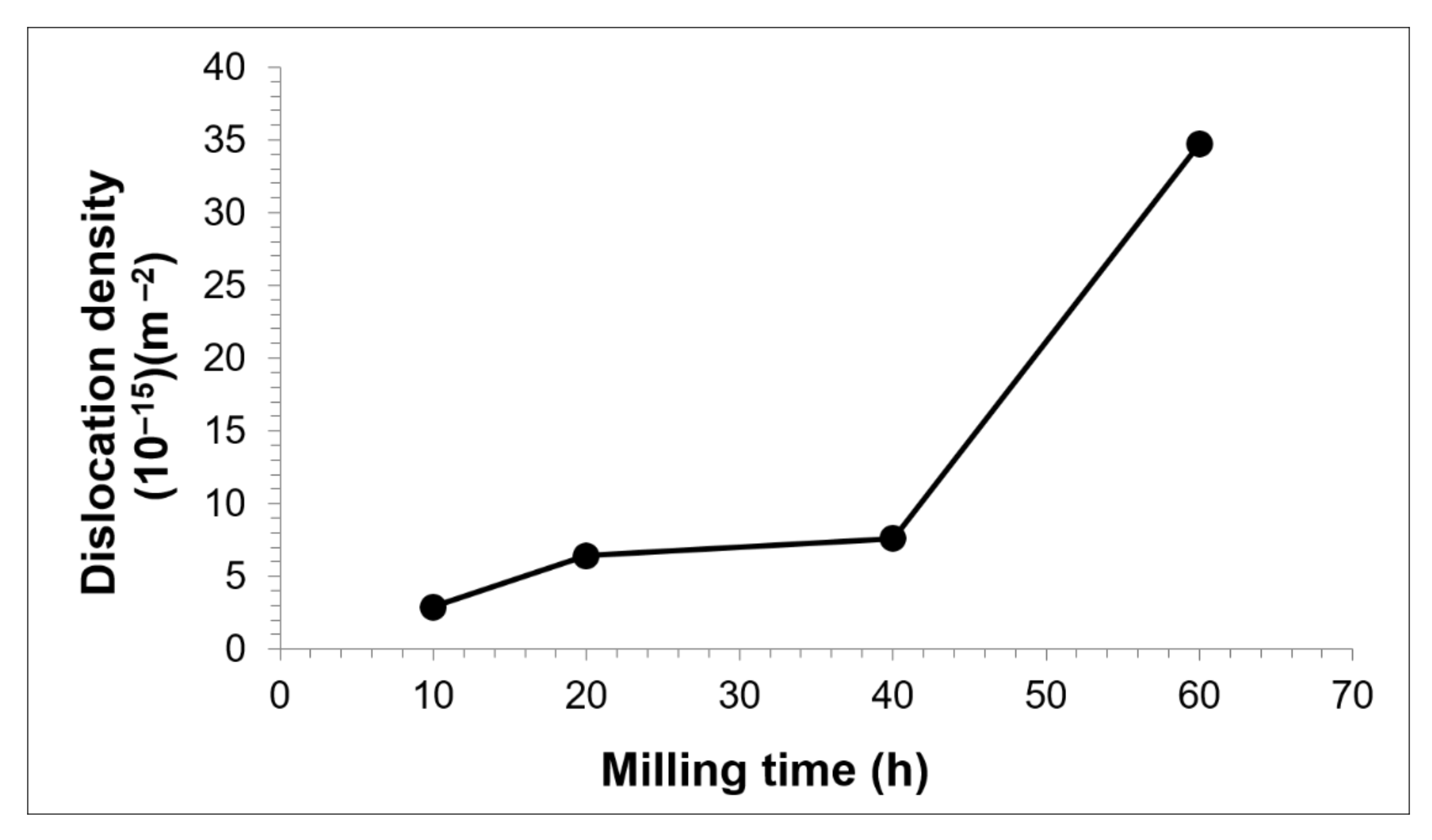
The broadening of the peak represents structural refinement that occurred in the as-milled powders. In this work, calculation of crystallite size and internal strain by Williamson–Hall only uses two high density peaks of Cu ((111) and (200) reflections) since another peak at higher angle tends to broaden and overlap with the W peak. Estimation of the crystallite size and internal strain has been done after removing the instrument broadening by reference sample of external Si standard. As shown in Figure 2, Cu crystallite size reduced to below 16 nm with increased milling time. As the powder mixtures undergo MA, plastic deformation causes Cu crystallite to slip passing through each other which contributes to the change of its size. At higher supplied energy to the powders, each crystallite remains constrained by its surrounding crystallites and produced stress/strain in the composite. Higher milling time should have lower Cu crystallite size due to the fact that repeated deformation occurs at a higher rate. Besides, decreases of crystallite size depend very much on the accumulation of defects. In most cases of MA product, the heavily stressed area is mainly caused by the increase in dislocation densities (Figure 3). Hence, Cu internal strain behaves inversely to that crystallite size for all milling times.
The solubility activity in the Cu-W-C mixture can be described by the variation of Cu lattice parameter against milling time, as shown in Figure 4. The lattice parameter was calculated using Cohen’s method for a cubic structure [33]. The plot clearly indicates that increases milling time increases the Cu matrix lattice parameter. For pure metals, milling duration has a minor effect on lattice changes [34,35]. Hence, the expansion of Cu matrix lattice from 0.363 nm (pure copper) was attribute to the formation of Cu(C) solution and Cu-W mixture. However, solute graphite in Cu matrix did not yield any significant effect because of its strictly Van der Waals interactions [36]. Due to the small difference in atomic radius between Cu and W atoms (0.138 and 0.128 nm, respectively), simultaneous atom substitution occurs, which is consistent with Vegard’s law’s principle. According to Vegard’s law, the lattice parameter of a two-phase solid solution is linearly related to the solute concentration. This variation is consistent with lattice change and imperfection caused by continuous particle deformation.
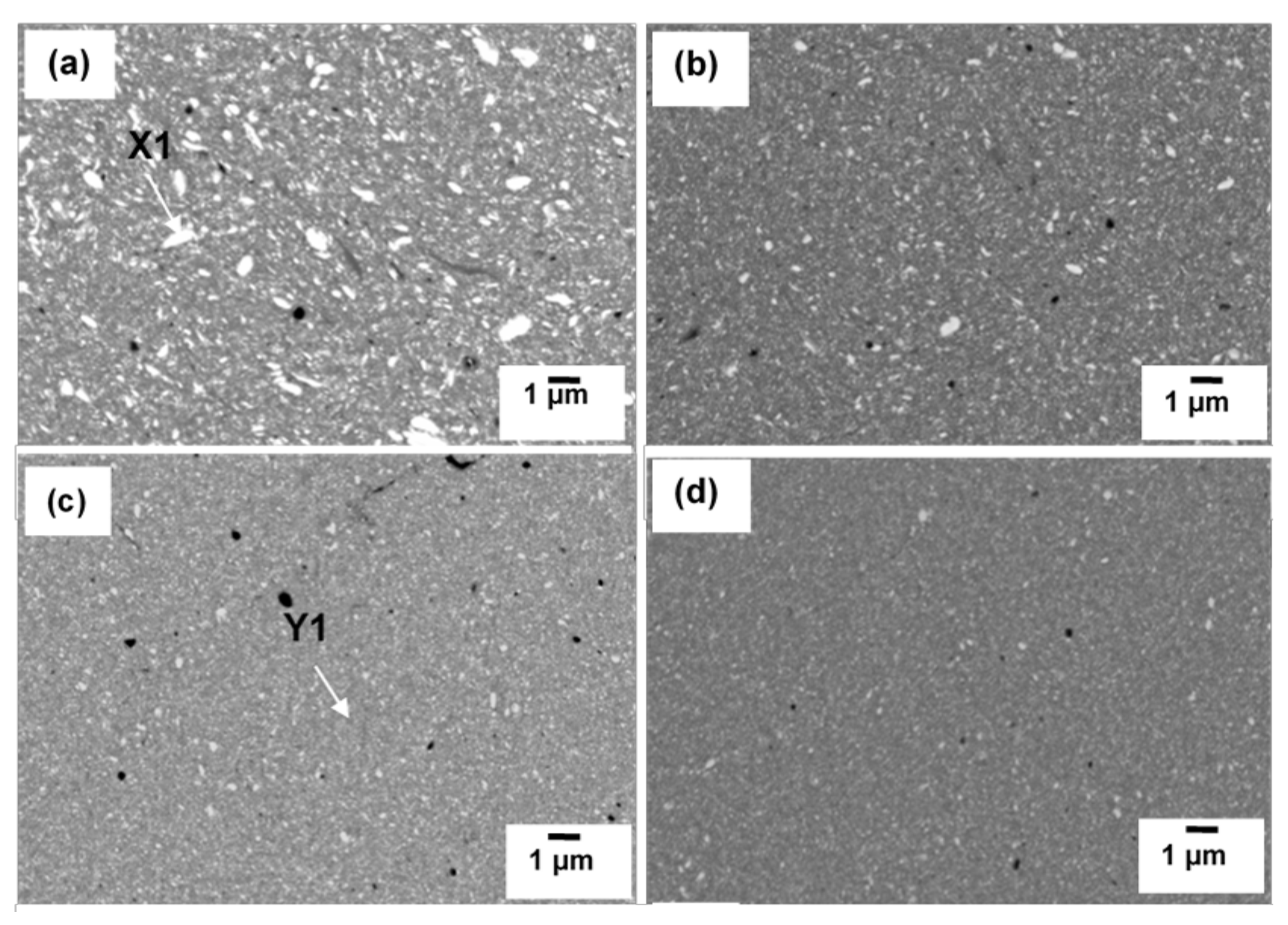
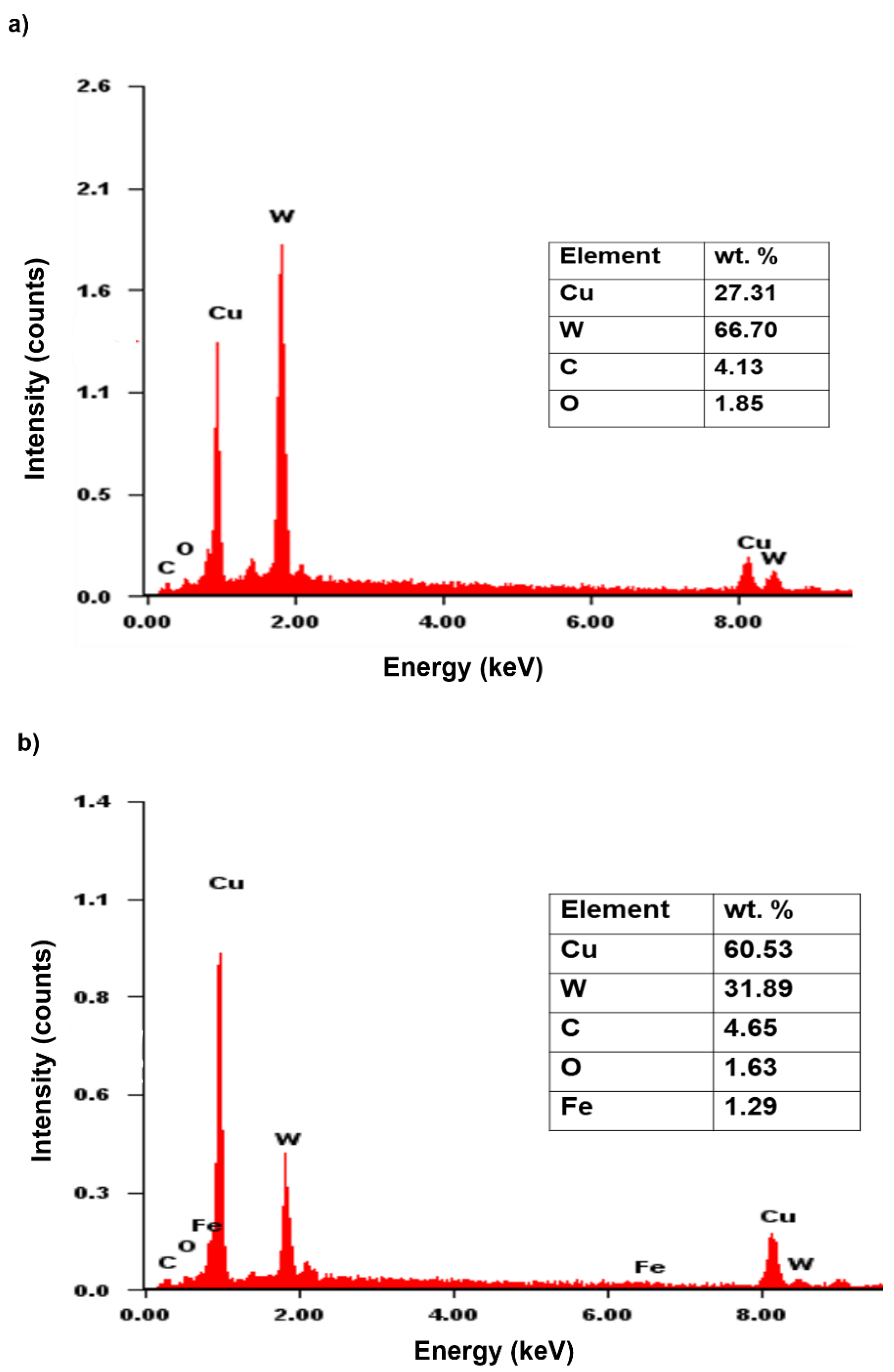
Figure 5 shows the SEM micrographs of as-milled Cu-W-C mixture after various milling times. Two kinds of particles can be obtained. The white particles represent rich sides of W whereas the grey particles are rich sides of Cu confirmed by EDX analysis in Figure 6. The as-milled powders in this figure show uniform particle distribution in all milling periods associated with small particle size and shape. In the beginning of milling (10 h), Cu particles were welded, whereas irregular W particles were embedded alongside the soft and ductile welded Cu. These particles became finer when milling time was increased owing to the beginning of particle fracturing as the milling reached 20 h and 40 h. Further milling to 60 h may heavily fracture the W particles with the conversion from irregular into spherical shape with average particle size of 1 μm.

3.2. Sintered Cu-W-C Composite

XRD patterns of sintered composite are shown in Figure 7 which indicates the diffraction lines of W gradually disappeared with increasing milling time. WC and W2C were traced at even lower milling time and there are no changes in the phases obtained, but the peak of W2C is reduced for 10 h to 40 h of milling. Between these two phases, W2C is suggested to form first, before WC, in less than 10 h of milling. The fact that W2C was first observed at lower milling time is because it is less thermodynamically stable than WC. WC and W2C have nearly equal stabilities at room temperature since heat formation of W2C only occurs at over 0.12 eV per carbon atom compared to WC (0.42 eV) [37]. However, W2C is found to be unstable at low temperature range from 677 to 1000 °C [38,39]. Furthermore, it is possible that lower milling has induced a lower amount of C to react with W than unreacted W [40,41,42]. W atoms have a greater number of W neighbors than in the W-C contact due to higher concentration of starting W. The reaction for the W2C formation can be suggested by Equation (1):
2 W + C W 2 C
Meanwhile, another important finding was that the heat supplied during sintering has successfully produced stable WC. This result indicates direct reaction of W + C WC has started at an even shorter time. Obviously, when milling time was extended, W2C phase reduced while WC phase increased. According to Bolokang et al., 2010, [41] and Mehrizi et al., 2019 [42], WC formation attributed to the reaction of W 2 C + C 2 WC and W + C WC are essentially obtained by higher available carbon distribution which can be produced at longer milling time. The extent of WC formation also behaves the same way after further milling. It may be that the reduced unreacted W and the disappearance of W2C peak at longer milling increased the WC phase.
WC or W2C was not formed during milling but somehow observed after subsequent sintering at 900 °C. The energy for the formation might came by both milling and heating since mechanical energy obtained from milling alone is insufficient to overcome the activation energy of tungsten carbide formation. Heavy internal refinement provided by milling brought C atoms into intimate contact with W leading to formation of W-C composite particles. With repeated fracturing and rewelding, defects and internal strain with greater amounts of grain boundaries were generated. Therefore, C atoms can diffuse along W grain boundaries as a result of many diffusion pathways having been created during the milling process. The finding of this work is in agreement with Li et al., 2019 [32], who proved that in situ formation of WC can only be obtained after MA and additional heat treatment, respectively. Although longer milling might provide more energy for the tungsten carbide formation, it could be useless when considering the Fe contamination from the milling jar and balls. In this work, further milling to 60 h did not yield enough energy to be supplied to the powders for tungsten carbide formation, but instead produced contaminated Fe3W3C phase, a trend which is similar to the work of Zhong et al., 2019 [43].
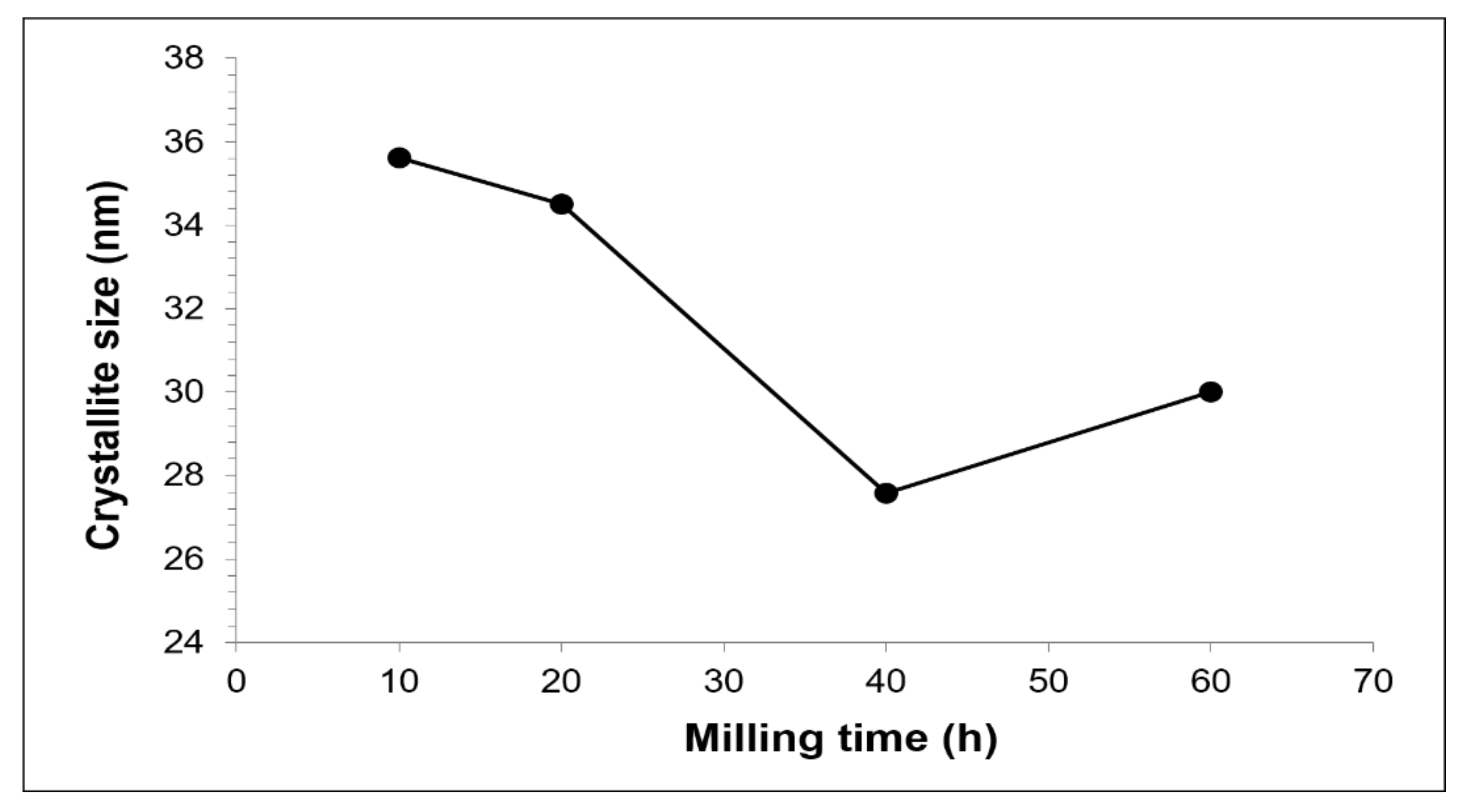
Figure 8 demonstrates the crystallite size of Cu with increasing milling time. The internal strain calculation was unsuccessful since the slope in the Williamson–Hall plot is linear for all milling times. Therefore, stress-free composite was obtained after sintering but still maintained its nanostructure. The lowest Cu crystallite size of the sintered composite was obtained by 40 h of milling because of the presence of hard second phases. It seems that faster diffusion is promoted by smaller crystallite size [44]. Baghani et al., 2018 [24], describes that crystallite size decrease is originated by atomic size mismatch among the phases in the CuFe-Al2O3 nanocomposite, which is also applicable to the explanation for Cu-W-C composite. Therefore, the increased of Cu crystallite size at 60 h milling is suggested to be as a result of the growth of Cu grain.
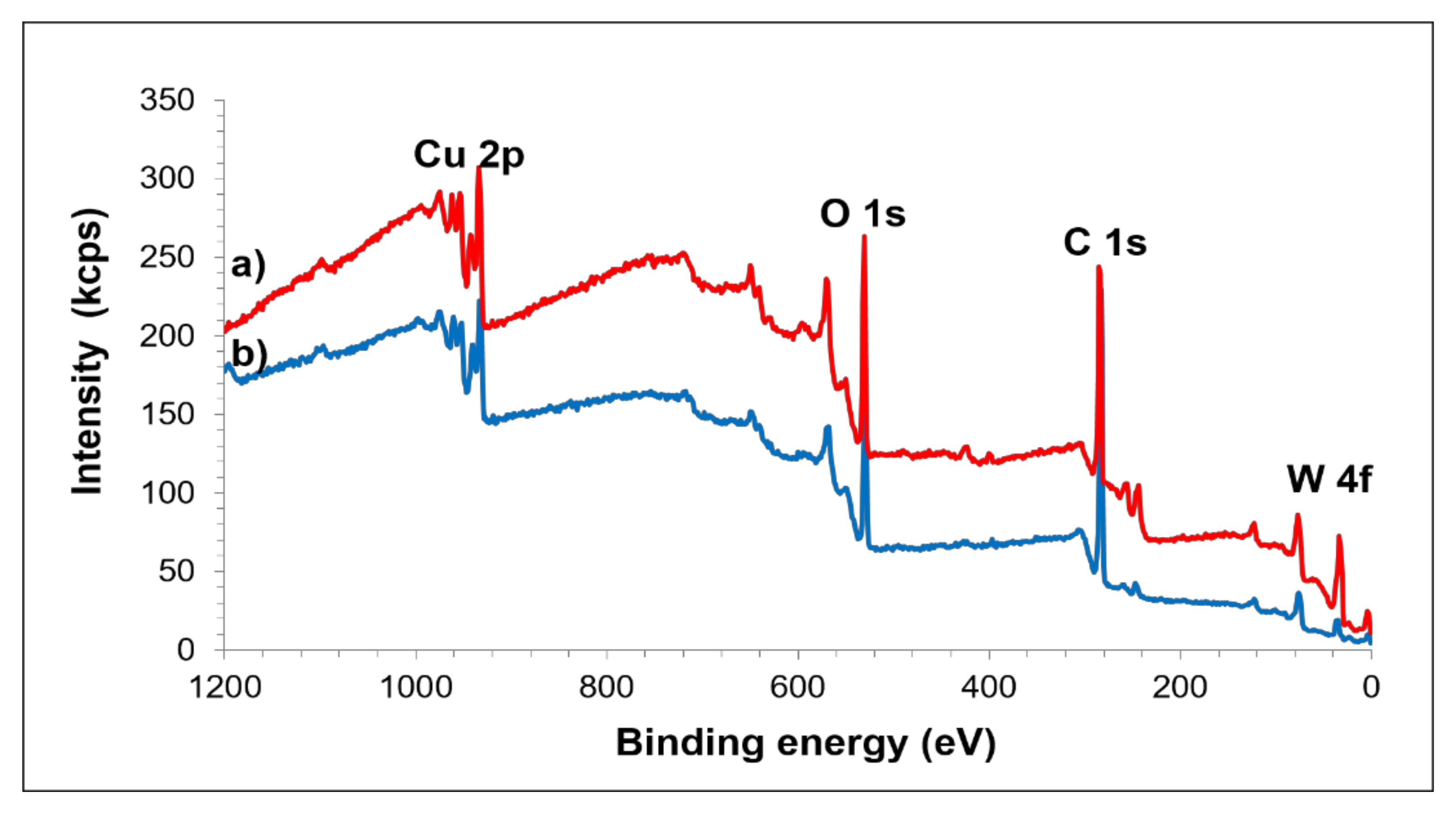
Results of XPS analysis on the composite prepared from powder milled for 40 h and the unmilled composite are shown in Figure 9. Spectra collected from wide scan were distinguished according to C 1s, O 1s, Cu 2p and W 4f. As can be seen, the XRD pattern of the composite milled at 40 h for the presence of tungsten carbide phase is well agreed and supported by XPS analysis. High intensity of graphite C 1s and W 4f peaks are determined in the composite milled for 40 h compared to that of the unmilled one, indicating that the MA process eventually altered the binding energy of the constituent elements.
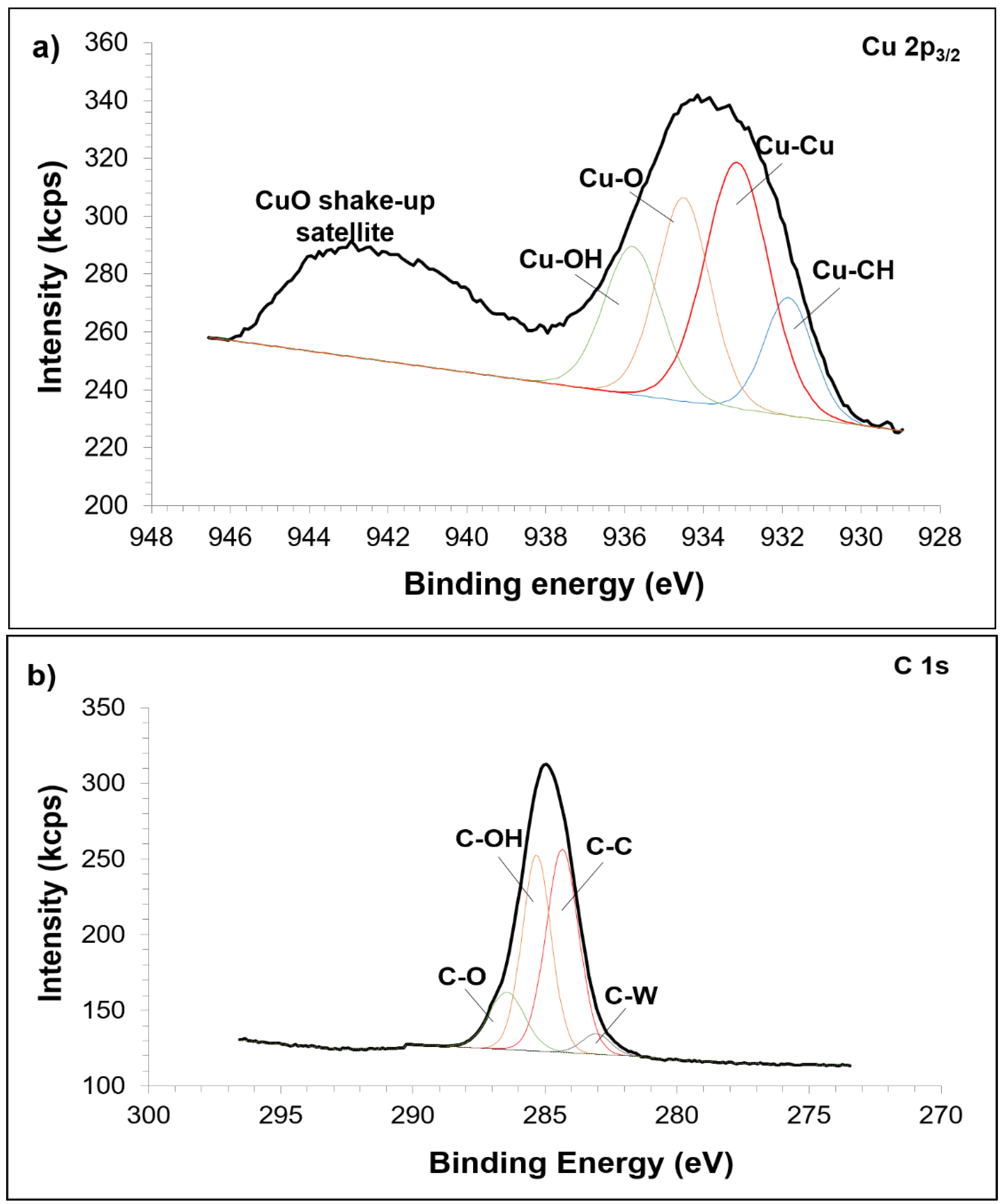
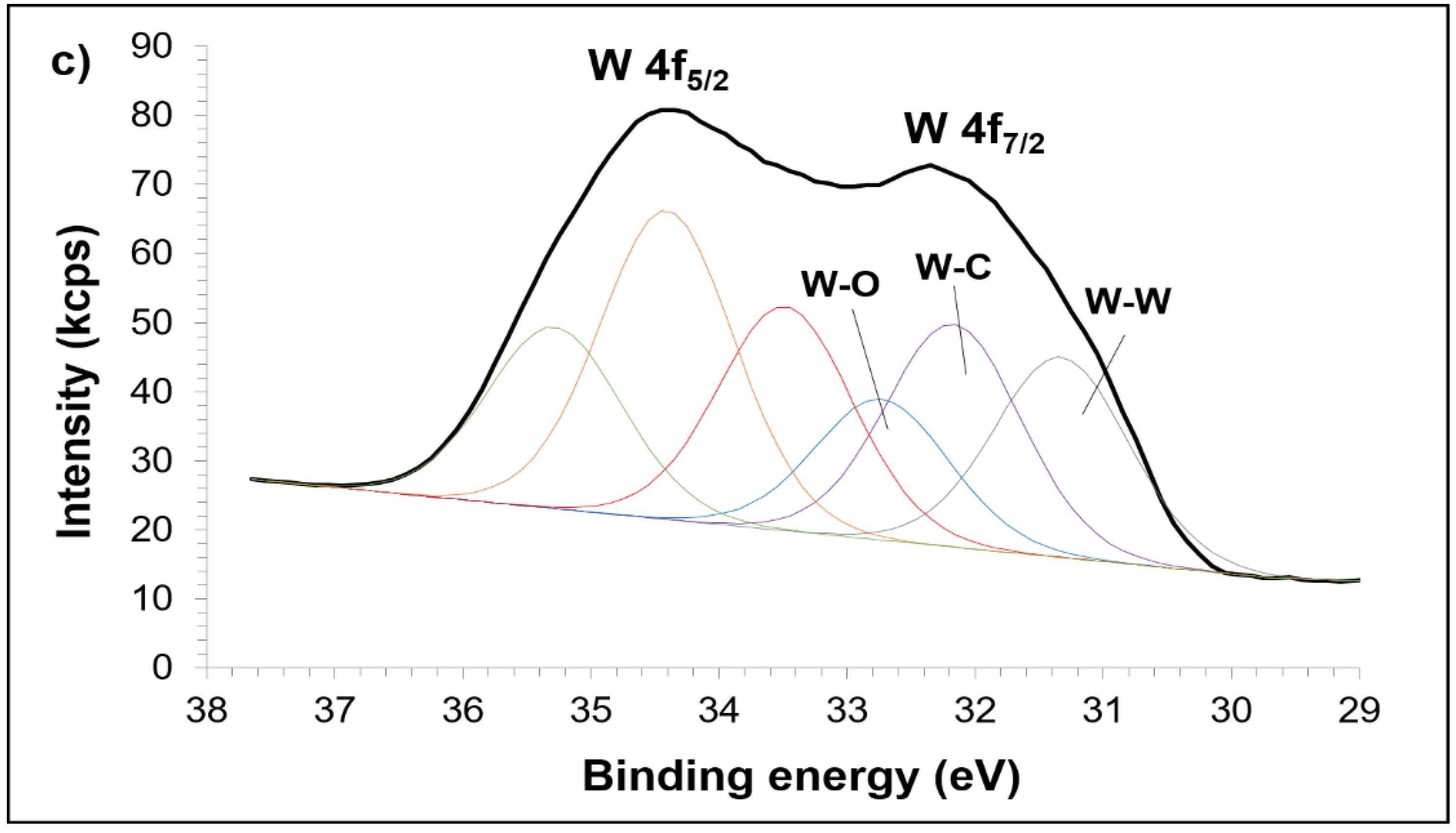
Figure 10 shows the high resolution XPS spectra for the composite milled for 40 h. The atomic interaction in Cu matrix is described in Figure 10a. The appearance of –OH and –CH groups showed that PCA did not completely decompose upon extensive milling and sintering which accumulates very much on the surface of the composite. Clearly, a strong shake-up satellite for CuO is also noted in this figure. A reasonable fit to Cu metallic is assigned at 933.15 eV peak. Meanwhile, the atomic level scan for C 1s spectra is presented in Figure 10b and fits to four interactions are seen. The first peak of C 1s at 283.06 eV is attributed to the reaction of W and C. Spectrum of graphite is recognized at 284.33 eV (second peak) and shifted compared to the unmilled composite. The third and fourth peaks are ascribed as contaminated phase. On the other hand, Figure 10c shows two resolved peaks corresponding to the W 4f5/2 and W 4f7/2. However, only W 4f7/2 will further be discussed. The peak located at 31.35 eV corresponds to the metallic W and the peak at 32.19 eV resulted from the reaction between W and C, which can be proved by the change of binding energy of W 4f that is obviously related to the change of C 1s electron. The chemical shift of W 4f and C 1s in this composite is highly dependent on the rate of defects [45,46] formed during MA. The other higher peak at 32.75 eV explained that the composite was contaminated by oxygen that can be suggested to originate either from milling or sintering.
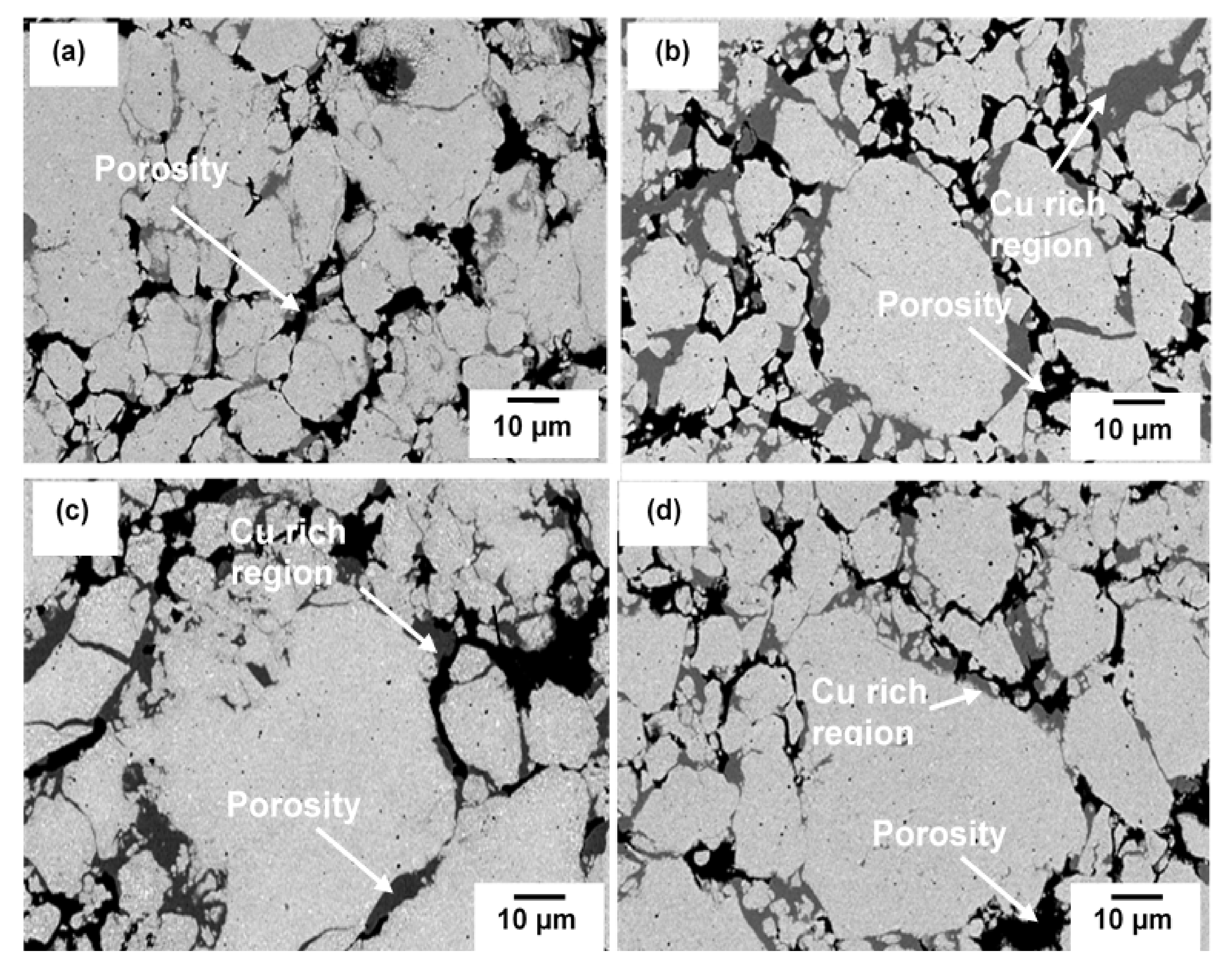
Figure 11 shows the SEM images of sintered composite at various milling times. Three areas can be distinguished in all milling times and consist of some non-uniformity of microstructure. The black area corresponds to porosities having various sizes and shape and the size reduced with increasing milling time. Very often, cold compaction leads to a porosity and void after sintering since there is a situation where no plastic deformation is involved during consolidation. The grey area consists of higher concentration of Cu and solution of Cu(C) which can be proved by elemental analysis in Figure 12. Tungsten carbide is more likely to solute in the Cu only at further milling. With the presence of tungsten carbide particles, the diffusion pathway of Cu particles is retarded, and much longer time may be needed to fracture into small size and distribute it in the Cu matrix. The regions identified in Figure 12 belong to higher accumulated of Cu where the other area was composed of Cu, W, Fe, O and C elements. Interparticle diffusion during sintering increased the homogeneity of microstructure, which can be shown by the area consisting of different color embedded in the red region (Cu) (Figure 12). Apart from that, there is no clear morphological difference between W2C and WC because WC was generated by transforming W2C, thus the microstructure should be identical.

4. Conclusions

Elemental Cu, W and C were used to synthesize nanostructured copper tungsten carbide. No carbide phase was obtained in the as-milled powder. It can only be formed after the sintering process. WC was formed with the coexistence of the reduction of W2C and unreacted W. Chemical shift of the composite proves that the composite contains W and C interaction that was promoted mainly by heavy deformation of MA. Progressive milling reduced the Cu crystallite size and increased the internal strain in the as-milled powder. The sintering process successfully relieved the stress in the composite while maintaining its nanostructure.

Author Contributions

Conceptualization, M.Y. and H.Z.; methodology, M.Y.; validation, H.Z.; investigation, M.Y.; resources, H.Z.; writing—original draft preparation, M.Y.; writing—review and editing, M.Y. and H.Z.; visualization, M.Y. and H.Z.; supervision, H.Z.; funding acquisition, H.Z. All authors have read and agreed to the published version of the manuscript.

Funding

This research was funded by the Research University Postgraduate Research Student Grant Scheme of Universiti Sains Malaysia (1001/PBAHAN/8041003) and National Science Fund provided by Ministry of Science, Technology and Innovation (MOSTI) Malaysia.

Institutional Review Board Statement

Not applicable.

Informed Consent Statement

Not applicable.

Data Availability Statement

The data presented in this study are available on request from the corresponding author.

Acknowledgments

This paper is part of research work conducted within the national research programs of the Ministry of Science, Technology and Innovation (MOSTI) Malaysia.

Conflicts of Interest

The authors declare no conflict of interest.

References

  1. Khosravi, J.; Givi, M.K.B.; Barmouz, M.; Rahi, A. Microstructural, mechanical, and thermophysical characterization of Cu/WC composite layers fabricated via friction stir processing. Int. J. Adv. Manuf. Technol. 2014, 74, 1087–1096. [Google Scholar] [CrossRef]
  2. Islak, S.; Kır, D.; Buytoz, S. Effect of sintering temperature on electrical and microstructure properties of hot pressed Cu-TiC composites. Sci. Sinter. 2014, 46, 15–21. [Google Scholar] [CrossRef]
  3. Mallikarjuna, H.M.; Ramesh, C.S.; Koppad, P.G.; Keshavamurthy, R.; Sethuram, D. Nanoindentation and wear behaviour of copper based hybrid composites reinforced with SiC and MWCNTs synthesized by spark plasma sintering. Vacuum 2017, 145, 320–333. [Google Scholar] [CrossRef]
  4. Chen, W.; Dong, L.; Wang, J.; Zuo, Y.; Ren, S.; Fu, Y. Synergistic enhancing effect for mechanical and electrical properties of tungsten copper composites using spark plasma infiltrating sintering of copper-coated graphene. Sci. Rep. 2017, 7, 9. [Google Scholar] [CrossRef]
  5. Shiri, S.G.; Abachi, P.; Pourazarang, K.; Rahvard, M.M. Preparation of in-situ Cu/NbC nanocomposite and its functionally graded behavior for electrical contact applications. Trans. Nonferrous Met. Soc. China 2015, 25, 863–872. [Google Scholar] [CrossRef]
  6. Tian, Y.; Dou, Z.; Niu, L.; Zhang, T. Effect of nanoboron carbide particles on properties of copper-matrix/graphite composite materials. Mater. Res. Express 2019, 6, 17938–17950. [Google Scholar] [CrossRef]
  7. Akbarpour, M.R.; Mousa Mirabad, H.; Alipour, S. Microstructural and mechanical characteristics of hybrid SiC/Cu composites with nano- and micro-sized SiC particles. Ceram. Int. 2019, 45, 3276–3283. [Google Scholar] [CrossRef]
  8. Prajapati, P.K.; Chaira, D. Fabrication and characterization of Cu–B4C metal matrix composite by powder metallurgy: Effect of B4C on microstructure, mechanical properties and electrical conductivity. Trans. Indian Inst. Met. 2019, 72, 673–684. [Google Scholar] [CrossRef]
  9. Xiang, S.; Hu, H.; Liang, Y.; Zhang, X. Fabrication of sub-stoichiometric titanium carbide-reinforced copper matrix composites using electropulsing-assisted flash sintering. Compos. Part A Appl. Sci. Manuf. 2021, 151, 106664. [Google Scholar] [CrossRef]
  10. Lin, H.; Guo, X.; Song, K.; Li, S.; Feng, J.; Zhang, X.; Feng, M. Synergistic strengthening effect of tungsten carbide (WC) particles and silicon carbide whiskers (SiCw) on mechanical properties of Cu–Al2O3 composite. J. Mater. Res. Technol. 2021, 15, 2837–2847. [Google Scholar] [CrossRef]
  11. Rajkumar, K.; Aravindan, S. Tribological performance of microwave sintered copper–TiC–graphite hybrid composites. Tribol. Int. 2011, 44, 347–358. [Google Scholar] [CrossRef]
  12. Umale, T.; Singh, A.; Reddy, Y.; Khatitrkar, R.; Sapate, S. In Abrasive wear behaviour of COPPER-SiC and COPPER-SiO2 composites. Int. J. Mod. Phys. Conf. Ser. World Sci. 2013, 22, 416–423. [Google Scholar] [CrossRef]
  13. Mishra, A. Dry sliding wear behaviourof titanium carbide with copper composites. Int. J. Mech. Eng. Robot. Res. 2014, 3, 4. [Google Scholar]
  14. Jha, P.; Gautam, R.K.; Tyagi, R. Friction and wear behavior of Cu–4 wt.% Ni–TiC composites under dry sliding conditions. Friction 2017, 5, 437–446. [Google Scholar] [CrossRef] [Green Version]
  15. Akbarpour, M.; Najafi, M.; Alipour, S.; Kim, H. Hardness, wear and friction characteristics of nanostructured Cu-SiC nanocomposites fabricated by powder metallurgy route. Mater. Today Commun. 2019, 18, 25–31. [Google Scholar] [CrossRef]
  16. Banthia, S.; Amid, M.; Sengupta, S.; Das, S.; Das, K. Reciprocating sliding wear of Cu, Cu-SiC functionally graded coating on electrical contact. J. Mater. Eng. Perform. 2020, 29, 3930–3940. [Google Scholar] [CrossRef]
  17. Deshpande, P.; Lin, R. Wear resistance of WC particle reinforced copper matrix composites and the effect of porosity. Mater. Sci. Eng. A 2006, 418, 137–145. [Google Scholar] [CrossRef]
  18. Toth, L. Transition Metal Carbides and Nitrides; Elsevier: Amsterdam, The Netherlands, 2014. [Google Scholar]
  19. Suryanarayana, C. Mechanical alloying: A novel technique to synthesize advanced materials. Research 2019, 2019, 4219812. [Google Scholar] [CrossRef] [Green Version]
  20. Suryanarayana, C.; Ivanov, E. Mechanochemical Synthesis of Nanocrystalline Metal Powders. In Advances in Powder Metallurgy; Elsevier Inc.: Amsterdam, The Netherlands, 2013. [Google Scholar]
  21. Zhang, G.; Gu, D. Synthesis of nanocrystalline TiC reinforced W nanocomposites by high-energy mechanical alloying: Microstructural evolution and its mechanism. Appl. Surf. Sci. 2013, 273, 364–371. [Google Scholar] [CrossRef]
  22. Zeng, W.; Zhou, D.; Zhang, D.; Li, X. Microstructural Evolution of Cu-10at% C Nanocomposite Powder During High Energy Mechanical Milling. Mater. Res. 2015, 18, 152–157. [Google Scholar] [CrossRef] [Green Version]
  23. Toozandehjani, M.; Matori, K.A.; Ostovan, F.; Abdul Aziz, S.; Mamat, M.S. Effect of milling time on the microstructure, physical and mechanical properties of Al-Al2O3 nanocomposite synthesized by ball milling and powder metallurgy. Materials 2017, 10, 1232. [Google Scholar] [CrossRef] [PubMed] [Green Version]
  24. Baghani, M.; Aliofkhazraei, M.; Seyfoori, A.; Askari, M. Mechanical alloying of CuFe-alumina nanocomposite: Study of microstructure, corrosion, and wear properties. Sci. Eng. Compos. Mater. 2018, 25, 1085–1094. [Google Scholar] [CrossRef]
  25. Şelte, A.; Özkal, B. Crystallite size and strain calculations of hard particle reinforced composite powders (Cu/Ni/Fe-WC) synthesized via mechanical alloying. Proc. Est. Acad. Sci. 2019, 68, 66–78. [Google Scholar] [CrossRef]
  26. Aghamiri, S.M.S.; Oono, N.; Ukai, S.; Kasada, R.; Noto, H.; Hishinuma, Y.; Muroga, T. Microstructure and mechanical properties of mechanically alloyed ODS copper alloy for fusion material application. Nucl. Mater. Energy 2018, 15, 17–22. [Google Scholar] [CrossRef]
  27. Sorkhe, Y.; Aghajani, H.; Tabrizi, A.T. Mechanical alloying and sintering of nanostructured TiO2 reinforced copper composite and its characterization. Mater. Des. 2014, 58, 168–174. [Google Scholar] [CrossRef]
  28. Taha, M.A.; Zawrah, M. Effect of nano ZrO2 on strengthening and electrical properties of Cu-matrix nanocomposits prepared by mechanical alloying. Ceram. Int. 2017, 43, 12698–12704. [Google Scholar] [CrossRef]
  29. Zang, J.; Li, H.; Sun, J.; Shen, Y.; Su, N.; Feng, X. Microstructure and thermal conductivity of Cu-Cu2AlNiZnAg/diamond coatings on pure copper substrate via high-energy mechanical alloying method. Surf. Interfaces 2020, 21, 100742. [Google Scholar] [CrossRef]
  30. Moustafa, E.B.; Taha, M.A. Preparation of high strength graphene reinforced Cu-based nanocomposites via mechanical alloying method: Microstructural, mechanical and electrical properties. Appl. Phys. A 2020, 126, 220. [Google Scholar] [CrossRef]
  31. Sun, J.; Zang, J.; Li, H.; Feng, X.; Shen, Y. Influence of diamond content and milling duration on microstructure and thermal conductivity of Ti-coated diamond/copper composite coating on copper substrate. Mater. Chem. Phys. 2021, 259, 124017. [Google Scholar] [CrossRef]
  32. Li, J.; Ni, J.; Huang, B.; Chen, J.; Xu, Z.; Liao, S.; Wang, C.; Luo, W. Long-term ball milling and hot pressing of in-situ nanoscale tungsten carbides reinforced copper composite and its characterization. Mater. Charact. 2019, 152, 134–140. [Google Scholar] [CrossRef]
  33. Cullity, B.; Stock, S. Elements of X-ray Diffraction; Prentice Hall: Upper Saddle River, NJ, USA, 2001; 388p. [Google Scholar]
  34. Zuo, B.; Saraswati, N.; Sritharan, T.; Hng, H.H. Production and annealing of nanocrystalline Fe–Si and Fe–Si–Al alloy powders. Mater. Sci. Eng. A 2004, 1–2, 210–216. [Google Scholar] [CrossRef]
  35. Kumar, R.; Bakshi, S.R.; Joardar, J.; Parida, S.; Raja, V.S.; Singh Raman, R.K. Structural evolution during milling, annealing, and rapid consolidation of nanocrystalline Fe–10Cr–3Al powder. Meterials 2017, 3, 272. [Google Scholar] [CrossRef] [PubMed]
  36. Berner, A.; Mundim, K.; Ellis, D.; Dorfman, S.; Fuks, D.; Evenhaim, R. Microstructure of Cu–C interface in Cu-based metal matrix composite. Sens. Actuators A Phys. 1999, 74, 86–90. [Google Scholar] [CrossRef]
  37. Cottrell, A. Chemical Bonding in Transition Metal Carbides; CRC Press: Boca Raton, FL, USA, 1995. [Google Scholar]
  38. Sohn, H.Y.; Ryu, T.; Choi, J.W.; Hwang, K.S.; Han, G.; Choi, Y.J.; Fang, Z.Z. The chemical vapor synthesis of inorganic nanopowders. J. Miner. Met. Mater. Soc. 2007, 59, 44–49. [Google Scholar] [CrossRef]
  39. Oh, J.H.; Kim, M.; Lee, Y.H.; Hong, S.H.; Kim, T.H.; Choi, S. Synthesis of tungsten carbide nanomaterials in triple DC thermal plasma jet system. J. Nanosci. Nanotechnol. 2019, 19, 6277–6284. [Google Scholar] [CrossRef]
  40. Tan, G.L.; Wu, X.J.; Zhao, M.H.; Zhang, H.F. Synthesis of nanocrystalline cubic substoichiometric WC1− z powders by mechanochemical technology. J. Mater. Sci. 2000, 35, 3151–3154. [Google Scholar] [CrossRef]
  41. Bolokang, S.; Banganayi, C.; Phasha, M. Effect of C and milling parameters on the synthesis of WC powders by mechanical alloying. Int. J. Refract. Met. Hard Mater. 2010, 28, 211–216. [Google Scholar] [CrossRef]
  42. Mehrizi, M.Z.; Momeni, M.; Beygi, R.; Kim, B.-H.; Kim, S.-K. Reaction pathway of NiAl/WC nanocomposite synthesized from mechanical activated NiAlWC powder system. Ceram. Int. 2019, 45, 11833–11837. [Google Scholar] [CrossRef]
  43. Zhong, L.; Deng, C.; Zhu, J.; Bai, H.; Xu, Y. Microstructure evolution and in-situ-formed mechanism of dual-scale WC-Fe reinforced iron matrix composites. J. Phys. Conf. Ser. 2020, 1605, 012185. [Google Scholar] [CrossRef]
  44. Ruoshan, L.; Guangrun, C.; Mingpu, W. Effect of Nb solute concentration on crystallite size refinement and strength enhancement in mechanically alloyed Cu-Nb Alloys. Rare Met. Mater. Eng. 2018, 47, 2607–2614. [Google Scholar] [CrossRef]
  45. Radajewski, M.; Schimpf, C.; Krüger, L. Study of processing routes for WC-MgO composites with varying MgO contents consolidated by FAST/SPS. J. Eur. Ceram. Soc. 2017, 37, 2031–2037. [Google Scholar] [CrossRef]
  46. Zhao, C.; Lu, H.; Wang, H.; Tang, F.; Nie, H.; Hou, C.; Liu, X.; Song, X.; Nie, Z. Solid-solution hardening of WC by rhenium. J. Eur. Ceram. Soc. 2020, 40, 333–340. [Google Scholar] [CrossRef]
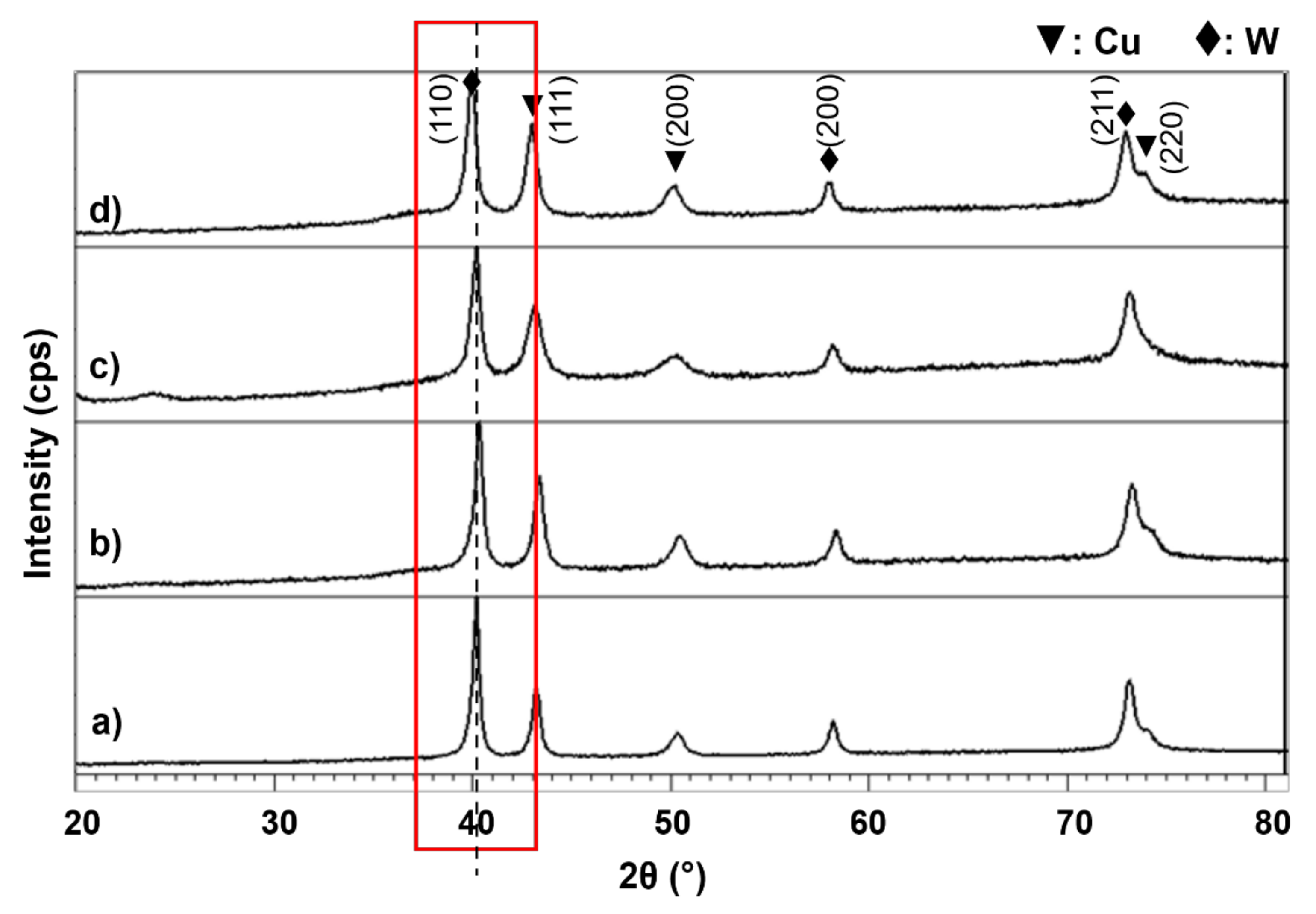
Figure 1. XRD patterns of the composite milled for (a) 10 h, (b) 20 h, (c) 40 h and (d) 60 h.
Materials 15 02340 g001
Figure 2. Cu crystallite size and internal strain of Cu-W-C powder for various milling time.
Materials 15 02340 g002
Figure 3. Dislocation density of as-milled Cu-W-C powder at various milling time.
Materials 15 02340 g003
Figure 4. Cu lattice parameter of Cu-W-C powder at various milling time.
Materials 15 02340 g004
Figure 5. SEM images of Cu-W-C powder milled for (a) 10 h, (b) 20 h, (c) 40 h and (d) 60 h.
Materials 15 02340 g005
Figure 6. EDX analysis of (a) white particle (X1 area) and (b) grey particle (Y1 area) corresponding to Figure 5a,c, respectively.
Materials 15 02340 g006
Figure 7. XRD patterns of Cu-W-C sintered composite milled for (a) 10 h (b) 20 h, (c) 40 h and (d) 60 h.
Materials 15 02340 g007
Figure 8. Cu crystallite size in Cu-W-C sintered composite at various milling times.
Materials 15 02340 g008
Figure 9. XPS wide scan spectra of the (a) sintered unmilled Cu-W-C mixture and (b) Cu-W-C sintered composite milled at 40 h.
Materials 15 02340 g009
Figure 10. XPS curve fitting for (a) Cu 2p, (b) C 1s and (c) W 4f for sintered composite milled for 40 h.
Materials 15 02340 g010aMaterials 15 02340 g010b
Figure 11. SEM images of Cu-W-C sintered composite milled at (a) 10 h, (b) 20 h, (c) 40 h and (d) 60 h.
Materials 15 02340 g011
Figure 12. (a) SEM image and elemental mapping on the corresponding area of (b) all elements, (c) Cu (red), (d) W (green), (e) Fe (indigo) and (f) C (yellow) in sintered compact milled at 40 h and sintered at 900 °C.
Materials 15 02340 g012
Publisher’s Note: MDPI stays neutral with regard to jurisdictional claims in published maps and institutional affiliations.