Article

Design, Fabrication, and Mechanical Properties of T-700TM Multiaxial-Warp-Knitting–Needled–C/SiC Composite and Pin

1
AECC (Aero Engine Corporation of China), Hunan Aviation Powerplant Research Institute, Zhuzhou 412000, China
2
Xi’an Golden Mountain Ceramic Composites Company, Xi’an 710065, China
3
National Key Lab of Thermostructure Composite Materials, Northwestern Polytechnical University, Xi’an 710072, China
4
College of Civil Aviation, Nanjing University of Aeronautics and Astronautics, No. 29 Jiangjun Ave., Nanjing 211106, China
*
Authors to whom correspondence should be addressed.
Materials 2022, 15(6), 2338; https://doi.org/10.3390/ma15062338
Submission received: 20 February 2022 / Revised: 14 March 2022 / Accepted: 18 March 2022 / Published: 21 March 2022
(This article belongs to the Special Issue Damage, Fracture and Fatigue of Ceramic Matrix Composites (CMCs))

Abstract

:
In this paper, the 12k T-700TM Multiaxial-Warp-Knitting–Needle (MWK–N) C/SiC composite and pin were designed and fabricated using the isothermal chemical vapor infiltration (ICVI) method. The composite’s microstructure and mechanical properties were examined by subjection to tensile and interlaminar shear tests. Three types of double-shear tests were conducted for C/SiC pins, including shear loading perpendicularly, along, and at 45° off-axial to the lamination. The fracture surface of the tensile and shear failure specimens was observed under scanning electronic microscope (SEM). The relationships between the composite’s microstructure, mechanical properties, and damage mechanisms were established. The composite’s average tensile strength was σuts = 68.3 MPa and the average interlaminar shear strength was τu = 38.7 MPa. For MWK–N–C/SiC pins, the double-shear strength was τu = 76.5 MPa, 99.7 MPa, and 79.6 MPa for test types I, II, and III, respectively. Compared with MWK–C/SiC pins, the double-shear strength of MWK–N–C/SiC pins all decreased, i.e., 26.7%, 50.8%, and 8% for test types I, II, and III, respectively. The MWK–N–C/SiC composite and pins possessed high interlaminar shear strength and double-shear strength, due to the needled fiber in the thickness direction, low porosity (10–15%), and high composite density (2.0 g/cm3).

1. Introduction

The C/SiC ceramic-matrix composites (CMCs) have excellent properties such as high-temperature resistance, thermal shock resistance, high strength, toughness, hardness, wear resistance, chemical stability, design tolerance, and low density and thermal expansion coefficients [1,2,3,4,5]. It can meet the requirements of long service life at a high temperature of 1650 °C and has broad application prospects in high thrust-to-weight ratio (TWR) aero engines, hypersonic ramjet engines, space shuttle thermal protection systems (TPS), and so on [6,7,8,9,10]. The HERMES, MSTP, ARD, GSTP, and FLPP programs of the European Space Agency (ESA) and the NASP, ISTP, Future-X, Hyper-X, and OTV programs of NASA have carried out relevant research and demonstration verification tests on C/SiC TPS. NASA used flaps, nose cones, and other components made of C/SiC composites in X-38, which reduced the weight of the X-38 thermal protection structure by 50% [11,12,13].
Three different techniques are currently used in an industrial scale for the production of C/SiC and C/C–SiC composites, i.e., chemical vapor infiltration (CVI), liquid polymer infiltration (LPI) or polymer infiltration and pyrolysis (PIP), and liquid silicon infiltration (LSI). Fiber orientation, dimensionality of the preform, and thermal treatment conditions are important parameters of influence on the performance of the final CMC product [10]. Due to the needs of inspection, disassembly, and maintenance, all parts of composite materials need to be connected. The connection of composite parts is of great significance for the design and application of CMCs. Common connection methods include adaptive robot ceramic joining technology [14,15,16], welding [17,18] and mechanical connection [19,20,21]. Mechanical connection refers to the connection of materials with fasteners, including bolts, rivets, and pins. Li et al. [22] fabricated the C/SiC nuts and bolts using the precursor infiltration and pyrolysis (PIP) process and analyzed the effect of fiber preforms, machining methods, and machining time on the mechanical properties of C/SiC nuts and bolts. Zhang et al. [23] fabricated the C/SiC z-pinned joint using the chemical vapor infiltration (CVI) method and analyzed the effect of porosity of the z-pin on the shear properties of a z-pinned joint. The critical porosity for the shear-controlled failure to bending-controlled fatigue was approximately 17.7%. Li et al. [24] investigated the microstructure and tensile behavior of C/SiC z-pinned joints. The average shear strength reaches τu = 157.7 MPa and the main failure mechanisms involved debonding of the lap interface and fiber shear-off within the pin. Around the hole, intact morphology, matrix crushing, and pin/hole debonding appeared. Liu et al. [25] performed numerical simulation and experimental validation of C/SiC riveting joints under tensile loading. A multiaxial-warp-knitting (MWK) structure possesses high tensile strength and elastic modulus, strong designability, and good shear resistance [26,27,28]. The in-plane mechanical properties of the MWK composite are better than that of the plain-woven composite [29]. To improve the interlaminar performance of the MWK composite, the needled fibers are incorporated in the Z direction. However, in the above-mentioned research, the mechanical properties of C/SiC composites or pins with the MWK and needled fiber (MWK–N–C/SiC) have not been investigated.
The objective of this paper is to fabricate the 12k T-700TM MWK–N–C/SiC composite and pin using the isothermal chemical vapor infiltration (ICVI) method and perform microstructure and mechanical properties experiments (i.e., tensile, interlaminar shear, and double-shear) on the composite and pin. Three types of double-shear tests are conducted for C/SiC pins, including shear loading perpendicularly, along, and at 45o off-axial to the lamination. The fracture surface of the tensile and shear failure specimens is observed under a scanning electronic microscope (SEM). The relationships between the composite microstructure, mechanical properties, and damage mechanisms are established. In Section 2, the fabrication method of the 12k T-700TM MWK–N–C/SiC composite and pin and the mechanical test procures for the tensile, interlaminar shear, and double-shear are introduced. In Section 3, the experimental results for the tensile and interlaminar shear of the composite, and the double-shear tests for three different types, are provided.

2. Fabrication of 12k T-700TM MWK–N–C/SiC Composite and Pin and Mechanical Experimental Procedure

In this section, the fabrication method for the 12k T-700TM MWK–N–C/SiC composite and pin is illustrated and the mechanical test procedures for determining the tensile, interlaminar, and double-shear properties for the composite and pins are also provided.

2.1. Fabrication of C/SiC Composite and Pins

The 12k T-700TM MWK–N–C/SiC composite and pins are fabricated using the isothermal chemical vapor infiltration (ICVI) method. The carbon fiber’s preform is multiaxial warp-knitted in 0°/±45°/90° with needled fibers in the Z direction. The fiber’s preform volume is 40–45%. The pyrolytic carbon (PyC) interphase is deposited on the surface of the T-700TM carbon fibers through the chemical reaction in Equation (1), and the PyC thickness is 0.1–0.2 μm. The deposition temperature is 1000 °C with a pressure of 5 kPa, a flow rate of Ar of 500 mL/min, C3H6 of 30 mL/min, and a deposition duration of 20 h.
2 C x H y ( g ) 2 xC ( g ) + yH 2 ( g )
After the deposition of the PyC interphase, the SiC matrix is deposited on the fiber’s preform with the PyC interphase through the chemical reaction in Equation (2):
CH 3 SiCl 3 ( g )   H 2   SiC ( s ) + 3 HCl ( g )
For the deposition of the SiC matrix, the fabrication temperature is 1000 °C; the pressure is 5 kPa; the flow rate of H2 is 100 mL/min; the mole mixture ratio between H2 and MTS is 10; and the deposition duration is 120 h. To increase the density of the SiC matrix, multiple CVI processes are conducted until the density of the C/SiC composite is above 2.0 g/cm3, and the porosity volume is 10–15%.
After the deposition of the SiC matrix, the surface of the C/SiC composite is coated with SiC to seal the open porosity, and the thickness of the SiC coating is 50–100 μm.

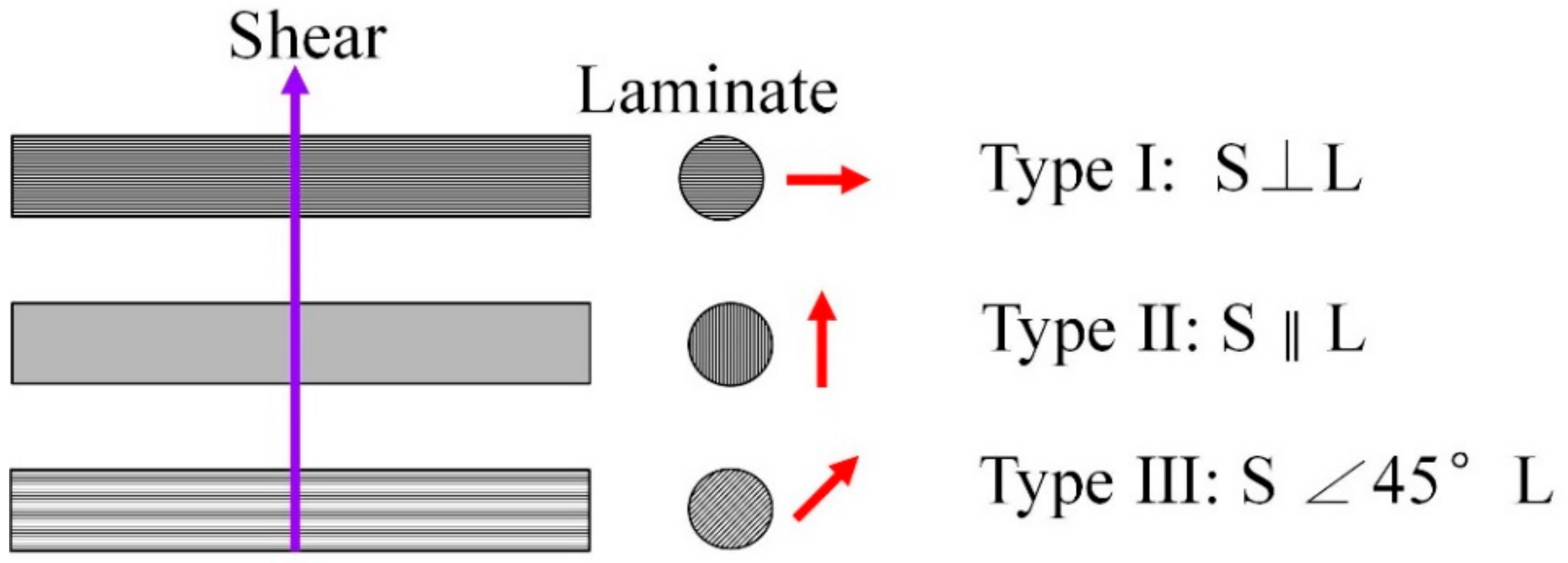
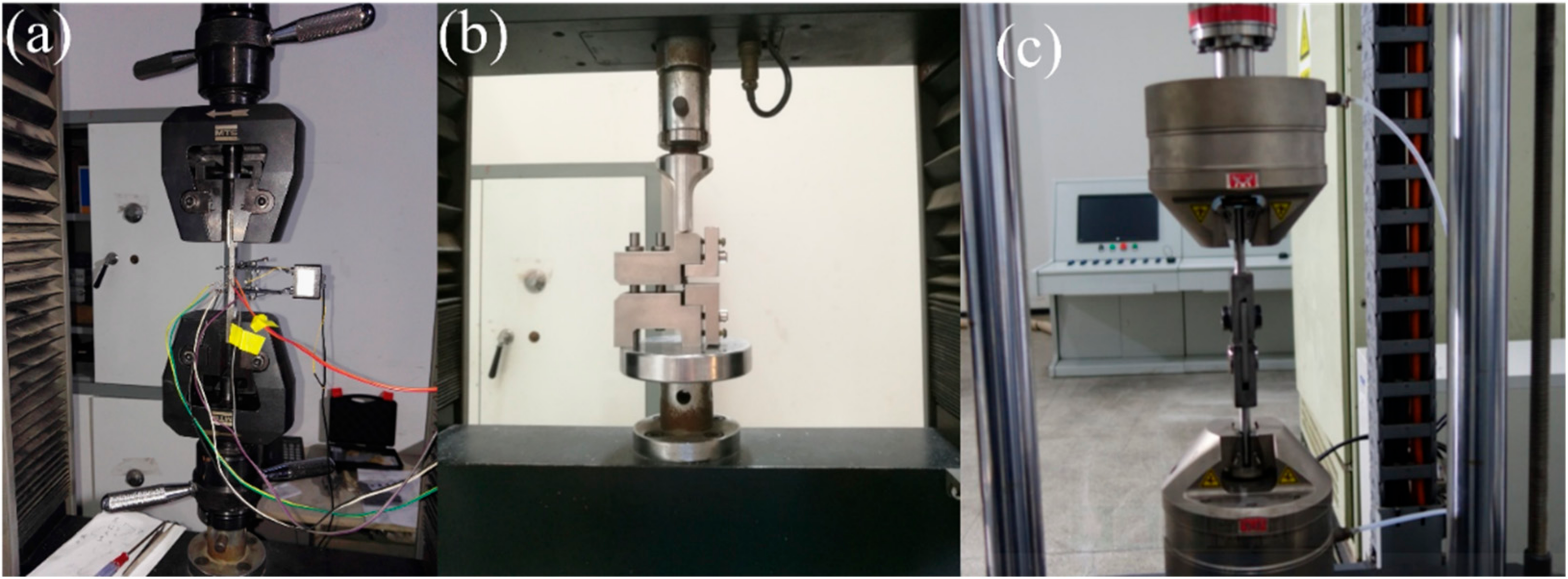
2.2. Mechanical Test Procedures

Figure 1a shows the monotonic tensile tests of the MWK–N–C/SiC composite. The tensile tests were conducted on an MTS CMT4304 testing machine (MTS Systems Corp., Minneapolis, MN, USA) following the ASTM-C1275 standard [30]. Tensile tests were under displacement control with a loading rate of 0.5 mm/min.
Figure 1b shows the interlaminar shear tests of the MWK–N–C/SiC composite. The interlaminar shear tests were conducted on an MTS CMT4304 testing machine (MTS Systems Corp., Minneapolis, MN, USA) following the ASTM-C1292 standard [31]. Interlaminar shear tests were under displacement control with a loading rate of 0.5 mm/min.
Figure 1c shows the double-shear tests of the MWK–N–C/SiC pin. Double-shear tests were conducted on an Instron E10000 testing machine (Instron Company, Norwood, MA, USA) under the displacement control with a loading rate 0.5 mm/min. The diameter of the pin was approximately 4.2 mm, and the length of the pin was 30 mm. Three types of double-shear tests were conducted for the C/SiC pins (as shown in Figure 2), including:
  • Type I, the shear loading is perpendicular to the lamination.
  • Type II, the shear loading is along the lamination.
  • Type III, 45° off-axial shear loading.

3. Experimental Results and Discussion

In this section, the tensile and interlaminar shear tests of the 12k T-700TM MWK–N–C/SiC composite are conducted. The tensile damage behavior and tensile and interlaminar shear fracture strength are analyzed. For the 12k T-700TM MWK–N–C/SiC pin, three double-shear tests are conducted. The double-shear fracture strength and related damage mechanisms are also discussed.

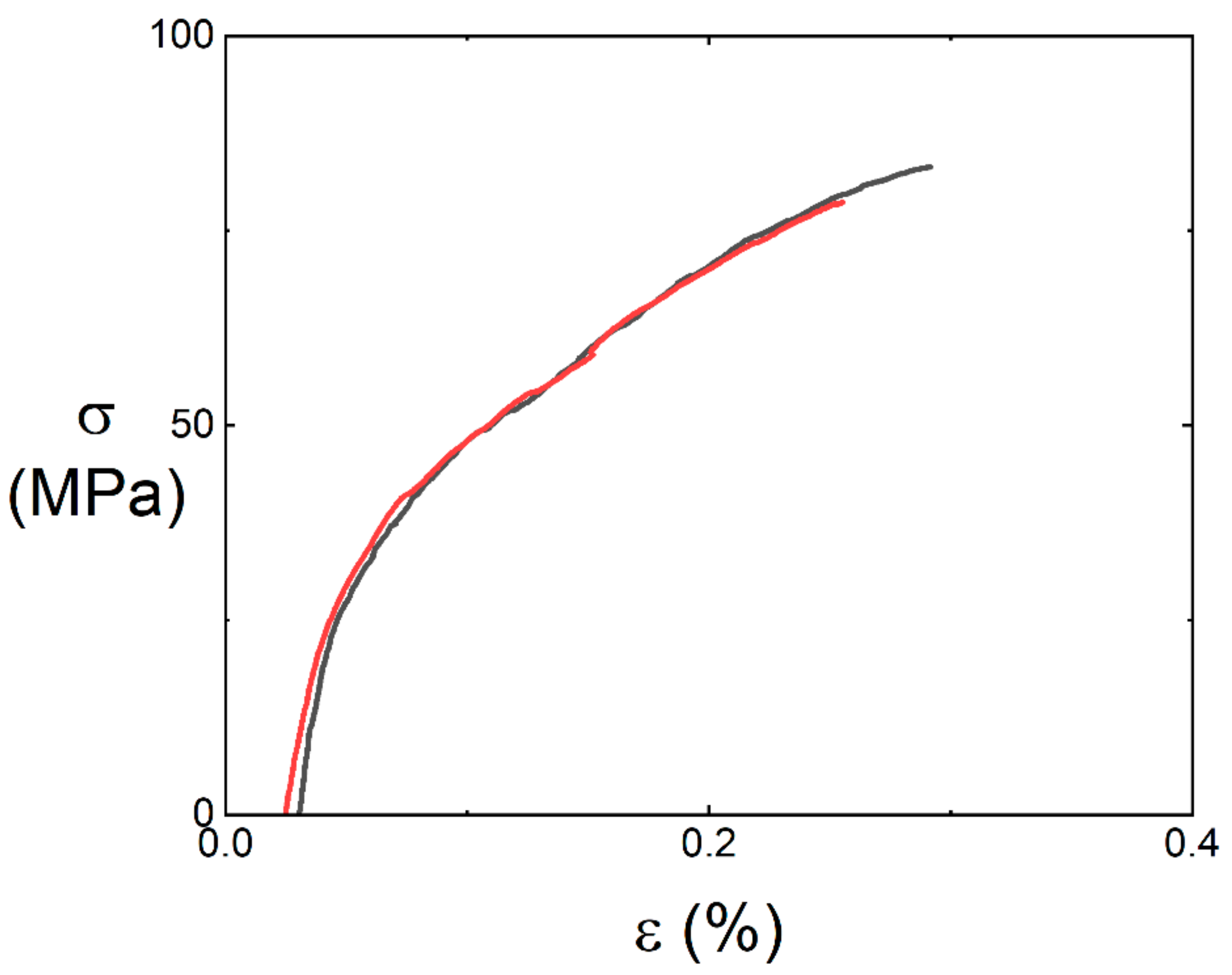
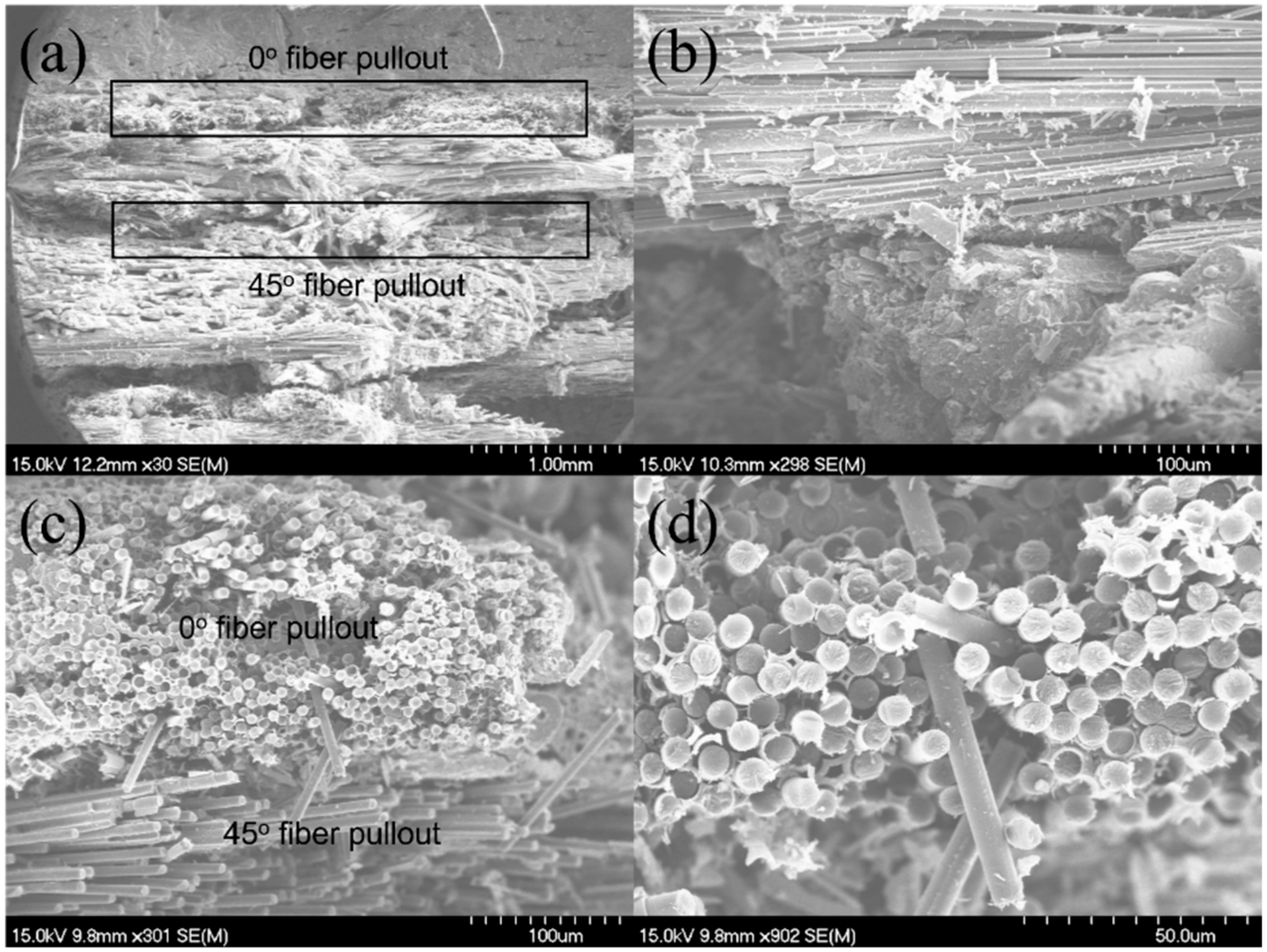
3.1. Tensile Behavior of 12k T-700TM MWK–N–C/SiC Composite

Tensile behavior of the 12k T-700TM MWK–N–C/SiC composite is investigated by subjection to tensile loading. After tensile fracture, the fracture surface of the sample is observed under a scanning electron microscope (SEM, FEI Company, Hillsboro, Ohio, USA) to show the tensile damage mechanisms. Figure 3 shows the tensile stress–strain curves of the 12k T-700TM MWK–N–C/SiC composites at room temperature. Table 1 shows the tensile mechanical properties of the 12k T-700TM MWK–N–C/SiC composites. Six samples were used to conduct the tensile experiments. The black and red curves in Figure 3 represent two samples for the tensile tests. The two samples’ tensile curves show obvious nonlinear behavior due to multiple damage mechanisms, e.g., matrix cracking, deflection of the cracks at the interface between the fiber and the matrix, and fiber fracture. The average composite tensile strength is σuts = 68.3 MPa and the average composite tensile modulus is E = 195.3 GPa.
After the tensile fracture, the failure specimens were observed under the SEM, as shown in Figure 4. There exists 0°, ±45°, 90°, and needled fibers along the Z direction in the SiC matrix. From the observation of the fracture surface, it can be found that long fiber pullout exists in the 0° and ±45° fibers, as shown in Figure 4a,b; and the needled fibers along the Z direction appeared in the pullout fibers in the 0° and ±45° fibers, as shown in Figure 4c,d.

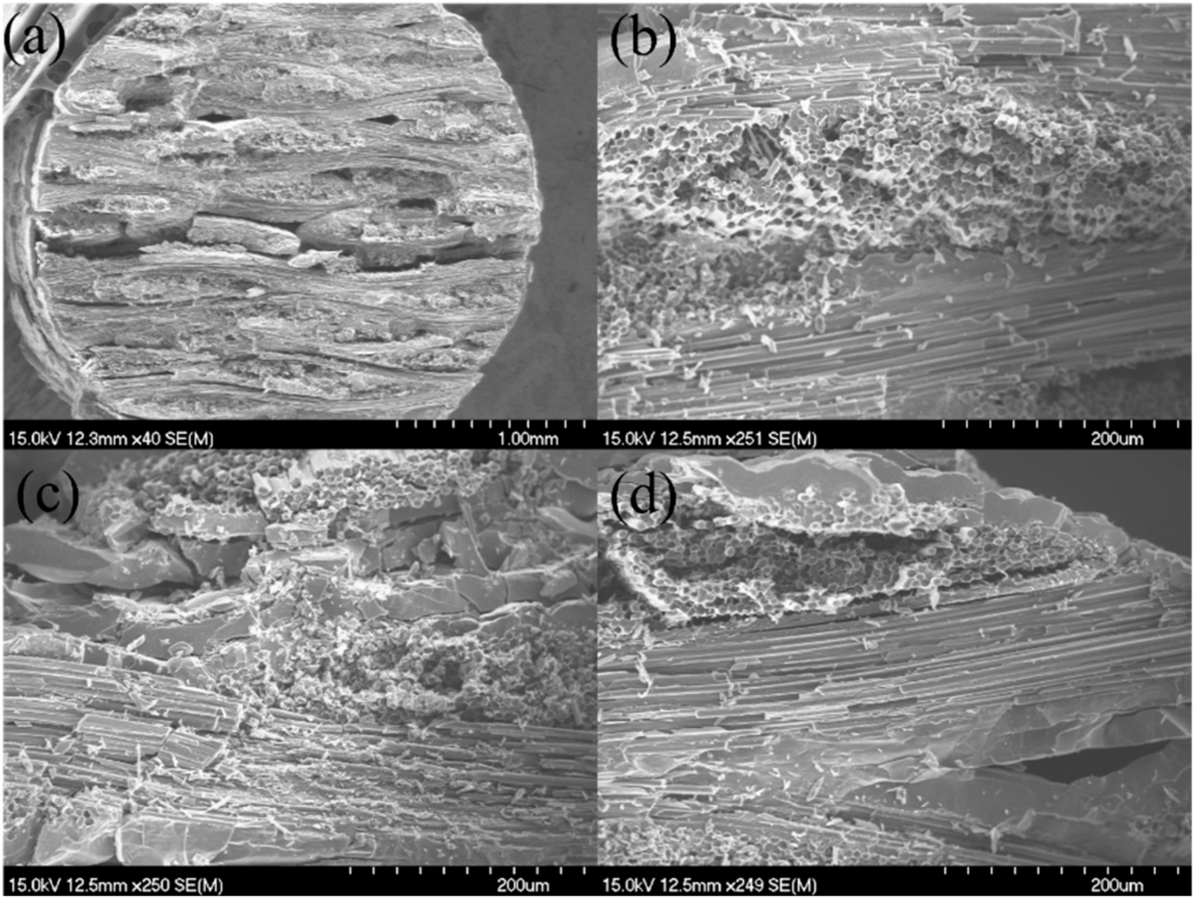
3.2. Interlaminar Shear Behavior of the 12k T-700TM MWK–N–C/SiC Composite

Interlaminar shear behavior of the 12k T-700TM MWK–N–C/SiC composite is investigated under the interlaminar shear test. After shear failure, the fracture surface of the samples is observed under the SEM. Table 2 lists the interlaminar shear properties of the 12k T-700TM MWK–N–C/SiC composite at room temperature. Five specimens were conducted for the interlaminar shear mechanical tests. The average interlaminar shear strength is τu = 38.7 MPa.
After interlaminar shear failure, the fracture specimens were observed under the SEM, as shown in Figure 5. Compared with the MWK–C/SiC composite without needled fibers in the Z direction as shown in Figure 5a,b, needled fiber fractures and pullout in the Z direction appear, as shown in Figure 5c,d.
Under interlaminar shear loading, the needled fibers increased the energy dissipation along the crack path and improved the interlaminar shear strength. Needled fibers along the thickness direction can improve the resistance for the crack propagation between the laminar.

3.3. Double-Shear Mechanical Behavior of the 12k T-700TM MWK–N–C/SiC Pins

The double-shear mechanical behavior of 12k T-700TM MWK–N–C/SiC pins is investigated for test types I, II, and III. Comparison analysis of the double-shear strength among the three test types is also conducted. Figure 6 shows the load-displacement (F-δ) curves of the 12k T-700TM MWK–N–C/SiC pins under double-shear loading for test types I, II, and III.
Figure 7 shows the double-shear strength of the 12k T-700TM MWK–N–C/SiC pins subjected to test types I, II, and III.
Table 3 lists the double-shear mechanical properties.
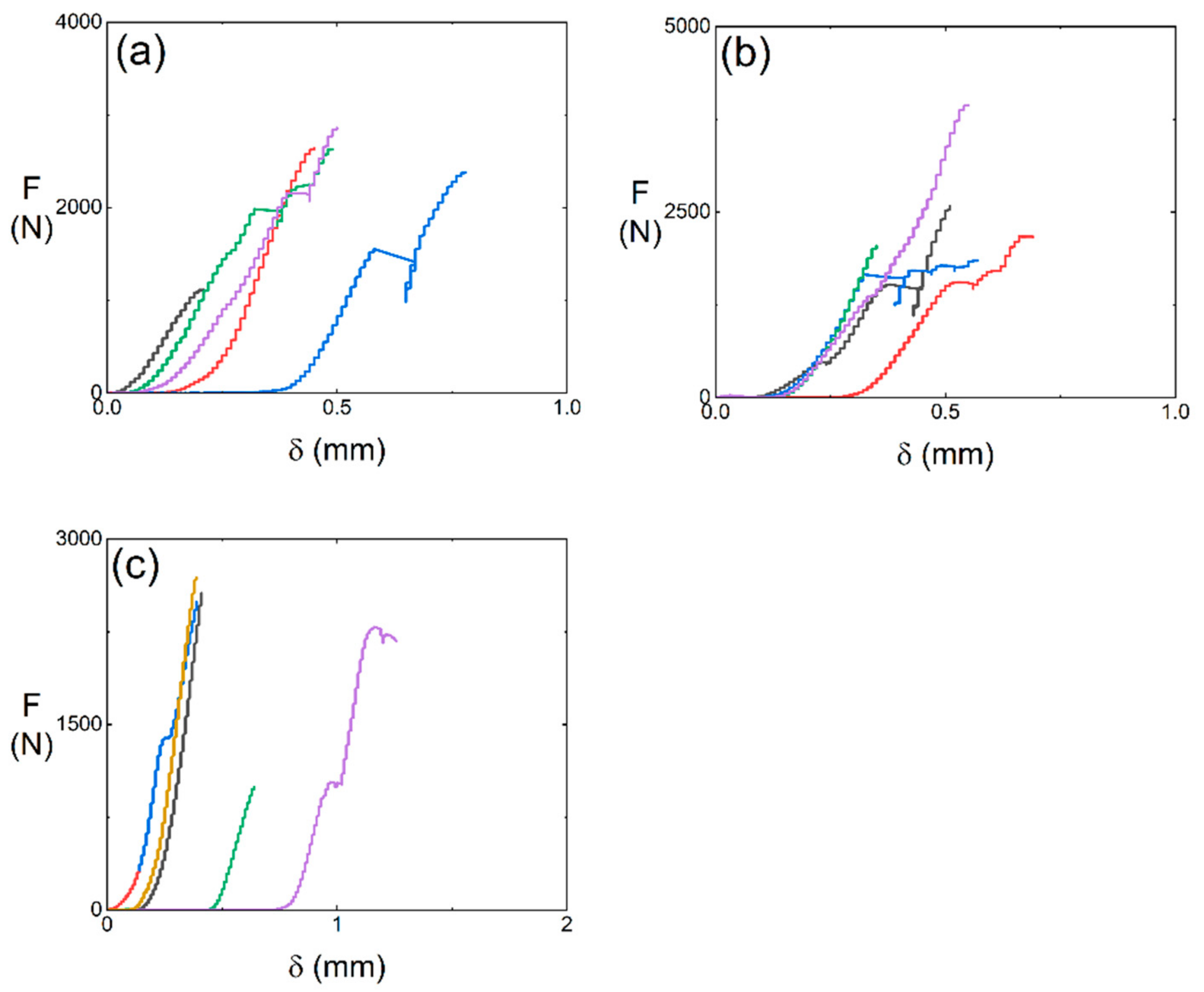
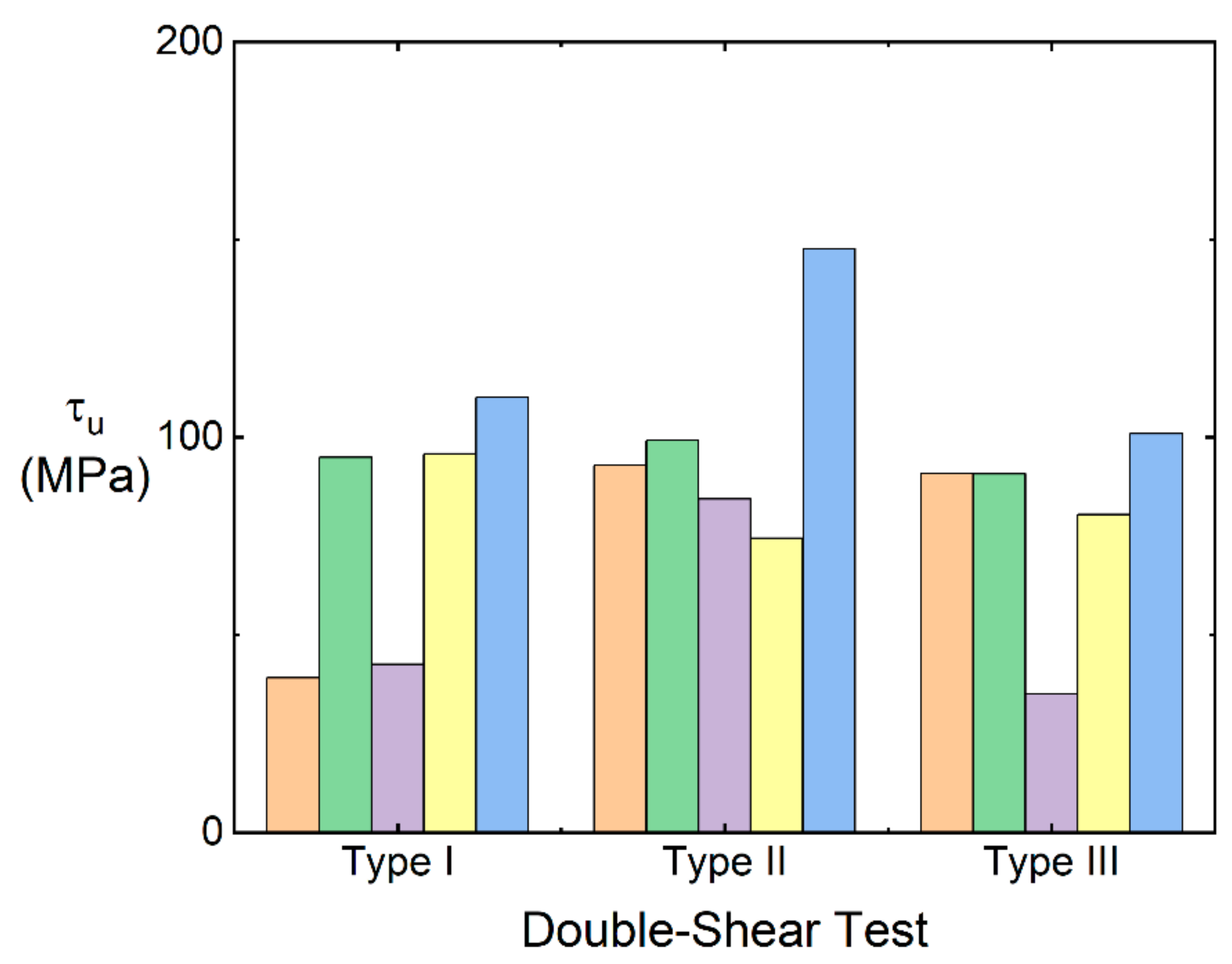
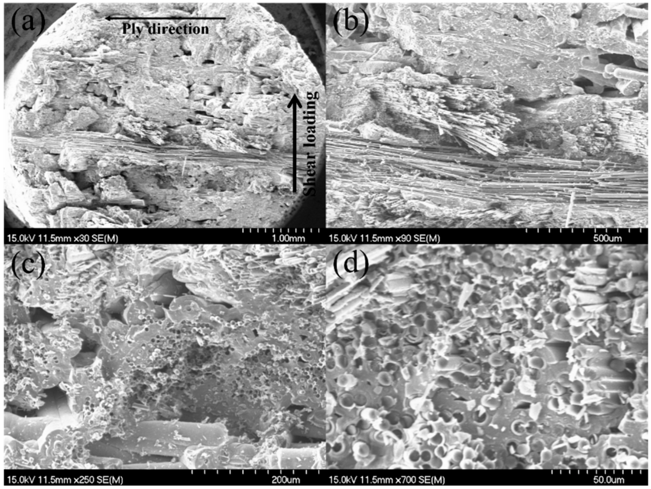
  • For test type I, five samples (i.e., #1~#5) were conducted for the double-shear test. The average double-shear strength is τu = 76.5 MPa.
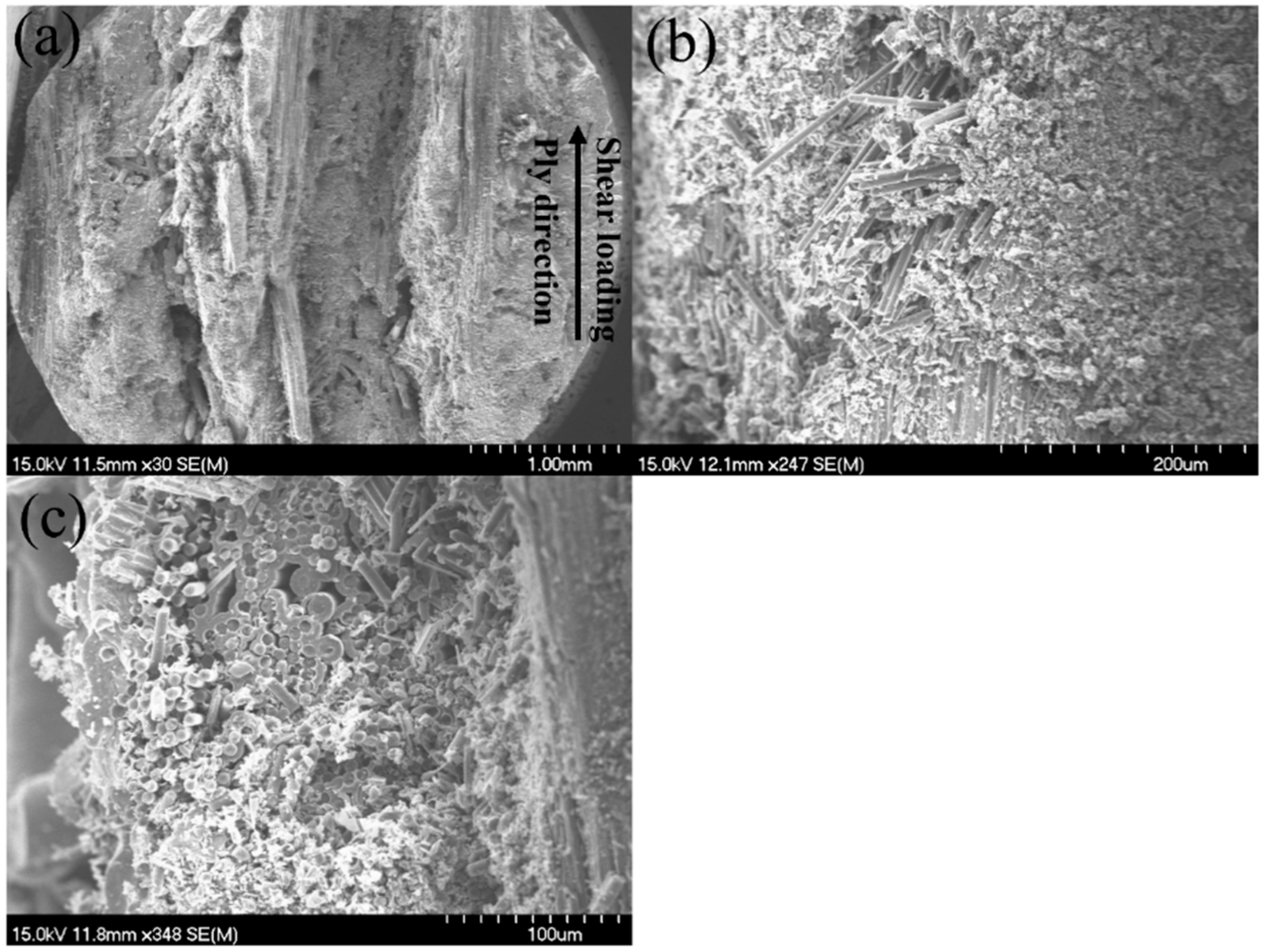
  • For test type II, five samples (i.e., #6~#10) were conducted for the double-shear test. The average double-shear strength is τu = 99.7 MPa.
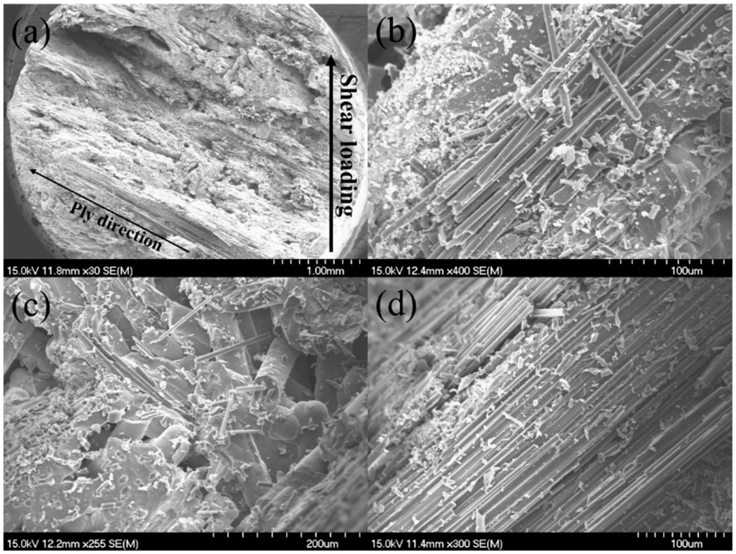
  • For test type III, five samples (i.e., #11~#15) were conducted for the double-shear test. The average double-shear strength is τu = 79.6 MPa.
For the 12k T-700TM MWK–C/SiC pins without needled fibers in the Z direction, the shear strength is τu = 104.3 MPa, 202.8 MPa, and 86.5 MPa for test types I, II, and III, respectively. Compared with the 12k T-700TM MWK–C/SiC pins without needled fibers in the Z direction, the double-shear strength of the MWK–N–C/SiC pins all decreases in test types I, II, and III. By introducing the needled fibers in the C/SiC pins, the interlaminar fracture toughness can increase, however, the double-shear strength decreases 26.7%, 50.8%, and 8% for test types I, II, and III, respectively.
Figure 8, Figure 9 and Figure 10 show the fracture surface of the 12k T-700TM MWK–N–C/SiC pins for the double-shear test types I, II, and III. On the fracture surface, there exists obvious fiber pullout in the 0° and ±45° fibers, which increases the fracture toughness before shear failure. However, compared with the MWK–C/SiC pins, there is porosity and holes in the MWK–N–C/SiC pins. The needled fiber destroys the continuity of the in-plane fiber bundle and reduces the bearing capacity of the in-plane fiber. The shear strength of the pin in all directions is similar, which shows the significant effect of reducing the anisotropy of pins with needled fibers.
Figure 11 shows the fracture surface of the 2D plain-woven C/SiC pin subjected to type I double-shear loading. Compared with the MWK–N–C/SiC pin, there are no needled fibers perpendicular to the lamination at the fracture surface, leading to the occurrence of the delamination between different plies.

3.4. Discussion

The mechanical properties of the C/SiC composites in the present analysis are compared with material data from other manufacturers. Table 4 lists the material data (e.g., tensile strength, Young’s modulus, and interlaminar shear strength, etc.) of the C/SiC composites fabricated using the CVI (isothermal), CVI (gradient), LPI, and LSI from NWPU, SNECMA, MAN, Dornier, MAN, and DLR. The tensile strength of MWK–N–C/SiC composite possessed low tensile strength compared with those C/SiC composites with (0°/90°) plain-woven (PW) fiber preform, due to the low fiber volume content along the tensile loading direction [32,33]. However, the Young’s modulus and interlaminar shear strength of the MWK–N–C/SiC composite were higher than those of the PW–C/SiC composite due to the needled fiber in the thickness direction, low porosity (10–15%), and high composite density (2.0 g/cm3). In fact, the needled fibers do not show high shear strength. On the other side, the decrease in the ceramic matrix porosity should have an exponential impact on the shear strength leading to a significant increase in its strength. For example, SICARBON™ materials produced by Airbus have a porosity higher than 20% and their interlaminar shear strength decreases from 15 MPa to 4 MPa when the porosity increases from 22 to 27% [34].

4. Summary and Conclusions

This paper fabricated 12k T-700TM MWK–N–C/SiC composites and pins using the ICVI method and performed microstructure and mechanical properties experiments on the composites and pin. Three types of double-shear tests were conducted for the C/SiC pins, including the shear loading perpendicularly, along, and at 45° off-axial to the lamination. The fracture surface of the tensile and shear failure specimens was observed under SEM. Relationships between the composite microstructure, mechanical properties, and damage mechanisms were established.
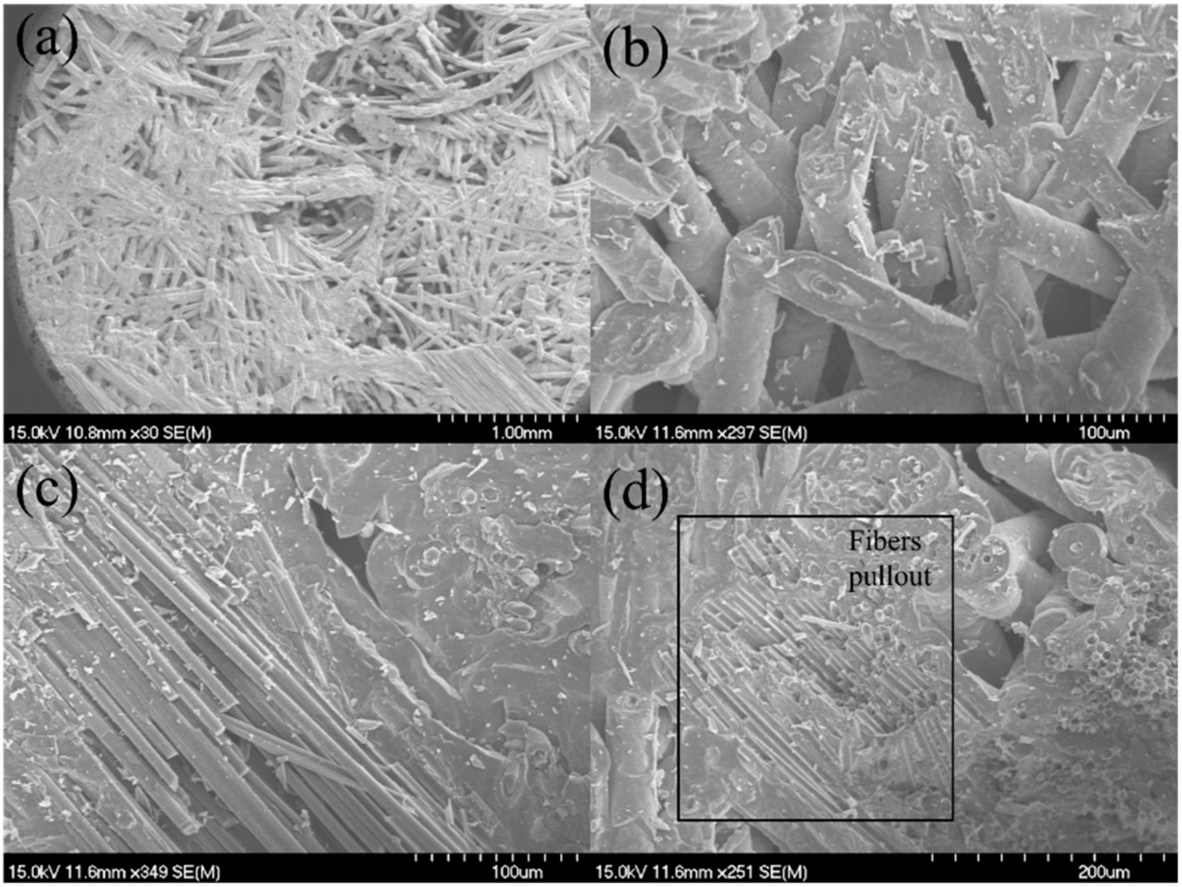
  • The average composite tensile strength was σuts = 68.3 MPa and the average composite tensile modulus was E = 195.3 GPa. At the fracture surface, long fiber pullout existed in the 0° and ±45° plies, and the needled fibers along the Z direction appeared in the pullout fibers in the 0° and ±45° fibers.
  • The average interlaminar shear strength was τu = 38.7 MPa. Compared with the MWK–C/SiC composite, needled fiber fracture and pullout appeared in the Z direction.
  • For the MWK–N–C/SiC pins, the double-shear strength was τu = 76.5 MPa, 99.7 MPa, and 79.6 MPa for test types I, II, and III, respectively. Compared with the MWK–C/SiC pins, the double-shear strength of the MWK–N–C/SiC pins all decreased, i.e., 26.7%, 50.8%, and 8% for test types I, II, and III, respectively.
  • The tensile strength of the MWK–N–C/SiC composite possessed low tensile strength compared with those C/SiC composites with (0°/90°) plain-woven (PW) fiber preform, due to the low fiber volume content along the tensile loading direction. The Young’s modulus and interlaminar shear strength of the MWK–N–C/SiC composite were higher than those of the PW–C/SiC composite, due to the needled fiber in the thickness direction, low porosity (10–15%), and high composite density (2.0 g/cm3).
Temperature affects the mechanical behavior of the material [35,36]. In further studies, the mechanical properties of the MWK–N–C/SiC pins at elevated temperatures will be investigated to establish the relationship between the mechanical properties, temperature, load, and environment.

Author Contributions

Conceptualization, X.L. (Xiao Luo), J.H., X.L. (Xiaochong Liu), Y.X., Q.W. and L.L.; methodology, X.L. (Xiao Luo), J.H., X.L. (Xiaochong Liu), X.G., Y.X. and L.L.; writing—original draft preparation, X.L. (Xiao Luo), X.L. (Xiaochong Liu), X.G., Y.X. and L.L.; writing—review and editing J.L. and Q.W. All authors have read and agreed to the published version of the manuscript.

Funding

This research was funded by the Fundamental Research Funds for the Central Universities of China, grant no. NS2019038.

Institutional Review Board Statement

Not applicable.

Informed Consent Statement

Not applicable.

Data Availability Statement

The data used to support the findings of this study are available from the paper.

Acknowledgments

The authors also wish to thank three anonymous reviewers and editors for their helpful comments on an earlier version of the paper.

Conflicts of Interest

The authors declare no conflict of interest. The funders had no role in the design of the study; in the collection, analyses, or interpretation of data; in the writing of the manuscript, or in the decision to publish the results.

References

  1. Naslain, R. Design, Preparation and properties of non-oxide CMCs for application in engines and nuclear reactors: An overview. Compos. Sci. Technol. 2004, 64, 155–170. [Google Scholar] [CrossRef]
  2. Li, L.B. Modeling temperature-dependent vibration damping in C/SiC fiber-reinforced ceramic-matrix composites. Materials 2020, 13, 1633. [Google Scholar] [CrossRef] [PubMed] [Green Version]
  3. Li, L.B.; Reynaud, P.; Fantozzi, G. Mechanical hysteresis and damage evolution in C/SiC composites under fatigue loading at room and elevated temperatures. Int. J. Appl. Ceram. Technol. 2019, 16, 2214–2228. [Google Scholar] [CrossRef]
  4. Li, L.B. High Temperature Mechanical Behavior of Ceramic-Matrix Composites; Wiley-VCH: Weinheim, Germany, 2021. [Google Scholar]
  5. Yang, X.; Feng, C.; Wang, Y.; Li, G.; Cao, J. Study on mechanical behavior of CVD-SiC coated C/SiC composites under simulated space environments. Appl. Compos. Mater. 2018, 25, 1093–1101. [Google Scholar] [CrossRef]
  6. Li, L.B. Durability of Ceramic Matrix Composites; Elsevier: Oxford, UK, 2020. [Google Scholar]
  7. Li, L.B. Tension-tension fatigue beahvior of unidirectional C/SiC ceramic-matrix composite at room temperature and 800 °C in air atmosphere. Materials 2015, 8, 3316–3333. [Google Scholar] [CrossRef] [Green Version]
  8. Li, L.B. Fatigue hysteresis behavior of cross-ply C/SiC ceramic matrix composites at room and elevated temperatures. Mater. Sci. Eng. A 2013, 586, 160–170. [Google Scholar] [CrossRef]
  9. Liu, X.C.; Guo, X.J.; Xu, Y.L.; Li, L.B.; Zhu, W.; Zeng, Y.Q.; Li, J.; Luo, X.; Hu, X. Cyclic Thermal shock damage behavior in CVI SiC/SiC high-pressure turbine twin guide vanes. Materials 2021, 14, 6104. [Google Scholar] [CrossRef]
  10. Krenkel, W. Carbon fibre reinforced silicon carbide composites (C/SiC, C/C-SiC). In Handbook of Ceramic Composites; Bansal, N.P., Ed.; Springer: Boston, MA, USA, 2005. [Google Scholar]
  11. Sygulla, D.; Sabath, D.; Püttmann, N.; Schmid, V.; Caporicci, M.; Anderson, B. The US-European Cooperation in the X-38 and CRV Programs. In Proceedings of the IAF Abstracts, 34th COSPAR Scientific Assembly, the Second World Space Congress, Houston, TX, USA, 10–19 October 2002. [Google Scholar]
  12. Christin, F. Design, fabrication and application of thermostructural composites (TSC) like C/C, C/SiC and SiC/SiC composites. Adv. Eng. Mater. 2002, 4, 903–912. [Google Scholar] [CrossRef]
  13. Hald, H.; Weihs, H.; Benitsch, B.; Fischer, I.; Reimer, T.; Winkelmann, P.; Gülhan, A. Development of a Nose Cap System for X-38. In Proceedings of the International Symposium Atmospheric Reentry Vehicles and Systems, Arcachon, France, 18–21 October 1999. [Google Scholar]
  14. Nicholas, M.G.; Peteves, S.D. Reactive joining: Chemical effects on the formation and properties of brazed and diffusion bonded interfaces. Scr. Mater. 1994, 31, 1091–1096. [Google Scholar] [CrossRef]
  15. Loehman, R.E. Recent progress in ceramic joining. Key Eng. Mater. 1999, 161–163, 657–662. [Google Scholar] [CrossRef] [Green Version]
  16. Ferraris, M.; Casalegno, V. Integration and joining of ceramic matrix composites. In Ceramic Matrix Composites: Materials, Modeling and Technology; Bansal, N.P., Lamon, J., Eds.; Wiley: Weinheim, Germany, 2015. [Google Scholar]
  17. Kang, S.; Dunn, E.M. Issue in ceramic-to-metal joining: An investigation of brazing a silicon nitride-based ceramic to a low expansion superalloy. Am. Ceram. Soc. Bull. 1989, 68, 1608–1617. [Google Scholar]
  18. Asthana, R.; Singh, M. Joining of partially sintered alumina to alumina, titanium, hastealloy and C-SiC composite using Ag-Cu brazes. J. Eur. Ceram. Soc. 2008, 28, 617–631. [Google Scholar] [CrossRef]
  19. Dano, M.L.; Gendron, G.; Picard, A. Stress and failure analysis of mechanically fastened joints in composite laminates. Compos. Struct. 2000, 50, 287–296. [Google Scholar] [CrossRef]
  20. Li, G.; Zhang, Y.; Zhang, C.; Hu, H.; Chen, S.; Zhang, Z. Design, preparation and properties of online-joints of C/SiC-C/SiC with pins. Compos. Part B 2013, 48, 134–139. [Google Scholar] [CrossRef]
  21. Li, G.; Wu, X.; Zhang, C.; Hu, H.; Zhang, Y.; Zhang, Z. Theoretical simulation and experimental verification of C/SiC joints with pins and bolts. Mater. Des. 2014, 53, 1071–1076. [Google Scholar] [CrossRef]
  22. Li, G.; Zhang, C.; Hu, H.; Zhang, Y. Preparation and mechanical properties of C/SiC nuts and bolts. Mater. Sci. Eng. A 2012, 547, 1–5. [Google Scholar] [CrossRef]
  23. Zhang, Y.; Zhang, L.; Zhang, J.; Yin, X.; Liu, C. Effects of z-pin’s porosity on shear properties of 2D C/SiC z-pinned joint. Compos. Struct. 2017, 173, 106–114. [Google Scholar] [CrossRef]
  24. Li, X.; Chen, X.; Chen, J.; Jiang, W.; Zhang, Y.; Chen, C. Fabrication and tensile behavior of plain woven C/SiC z-pinned joint. J. Chin. Ceram. Soc. 2021, 49, 1206–1212. [Google Scholar]
  25. Liu, Y.; Hu, C.; Wang, Q.; Cheng, L.; Zhang, L. Numerical simulation and experimental validation of stress in C/SiC riveting joints under tensile load. Acta Mater. Compos. Sin. 2013, 30, 205–210. [Google Scholar]
  26. Chun, H.-J.; Kim, H.-W.; Byun, J.-H. Effects of through-the-thickness stitches on the elastic beahvior of multi-axial warp knit fabric composites. Compos. Struct. 2006, 74, 484–494. [Google Scholar] [CrossRef]
  27. Gao, X.P.; Li, D.X.; Wu, W.; Chen, S. Experimental investigation of the tensile and bending behavior of multi-axial warp knitted fabric composites. Text. Res. J. 2018, 88, 333–344. [Google Scholar] [CrossRef]
  28. Li, D.-S.; Yang, Y.; Wang, Z.; Jiang, L. Experimental investigation on mechanical response and failure analysis of 3D multi-axial warp knitted hybrid composites. Compos. Struct. 2020, 246, 112340. [Google Scholar] [CrossRef]
  29. Kamiya, R.; Cheeseman, B.A.; Popper, P.; Chou, T.-W. Some recent advances in the fabrication and design of three-dimensional textile preforms: A review. Compos. Sci. Technol. 2000, 60, 33–47. [Google Scholar] [CrossRef]
  30. ASTM-C1275; Standard Test Method for Monotonic Tensile Behavior of Continuous Fiber-Reinforced Advanced Ceramics with Solid Rectangular Cross-Section Test Specimens at Ambient Temperature. ASTM: West Conshohocken, PA, USA, 2018.
  31. ASTM-C1292; Standard Test Method for Shear Strength of Continuous Fiber-Reinforced Advanced Ceramics at Ambient Temperatures. ASTM: West Conshohocken, PA, USA, 2022.
  32. Li, L.B. A time-dependent tensile constitutive model for long-fiber-reinforced unidirectional ceramic-matrix minicomposites considering interface and fiber oxidation. Int. J. Damage Mech. 2020, 29, 1138–1166. [Google Scholar]
  33. Li, L.B. Effect of stochastic loading on tensile damage and fracture of fiber-reinforced ceramic-matrix composites. Materials 2020, 13, 2469. [Google Scholar] [CrossRef]
  34. Galizia, P.; Sciti, D.; Jain, N. Insight into microstructure and flexural strength of ultra-high temperature ceramics enriched SICARBONTM composite. Mater. Des. 2021, 208, 109888. [Google Scholar] [CrossRef]
  35. Chao, W.; Xiangxin, X.; Xiaozhou, C.; He, Y.; Gongjin, C. The effect of Ti addition on the microstructure and fracture toughness of Bn-Al composite materials synthesized by vacuum infiltration. Arch. Metall. Mater. 2013, 58, 509–512. [Google Scholar] [CrossRef] [Green Version]
  36. Du, Q.; Gao, Y.; Ren, Z.H.; Cao, X.M.; Wang, C.; Zhang, J.S. Preparation and erosion performance for co-continuous phase composites of Si3N4/1Cr18Ni9Ti. Chin. J. Mater. Res. 2019, 33, 34–42. [Google Scholar]
Figure 1. Mechanical tests of C/SiC composite and pins. (a) Tensile; (b) interlaminar shear; and (c) double-shear.
Materials 15 02338 g001
Figure 2. Schematic of three types of double-shear tests for the C/SiC pin.
Materials 15 02338 g002
Figure 3. Monotonic tensile stress–strain curves of the 12k T-700TM MWK–N–C/SiC composite.
Materials 15 02338 g003
Figure 4. Tensile fracture surface of the 12k T-700TM MWK–N–C/SiC specimen observed under SEM. (a) fibers pullout in the 0° and 45° plies; (b) fiber pullout in the 0° plies; (c) 0° and 45° fiber pullout; (d) fiber pullout in the 0° plies.
Materials 15 02338 g004
Figure 5. Interlaminar shear fracture surface of the 12k T-700TM MWK–N–C/SiC specimen observed under SEM. (a) fracture surface of MWK–C/SiC specimen; (b) fracture fiber of MWK–C/SiC specimen; (c) needled fiber fracture in MWK–N–C/SiC specimen; (d) needled fiber pullout in MWK–N–C/SiC specimen.
Materials 15 02338 g005
Figure 6. Double-shear load-displacement curves of the 12k T-700TM MWK–N–C/SiC pins: (a) type I; (b) type II; and (c) type III.
Materials 15 02338 g006
Figure 7. Double-shear strength of the 12k T-700TM MWK–N–C/SiC pins.
Materials 15 02338 g007
Figure 8. Type I double-shear fracture surface of the 12k T-700TM MWK–N–C/SiC pin observed under SEM. (a) fracture surface; (b) fiber pullout in different plies; (c) fiber pullout; (d) fiber fracture and pullout.
Materials 15 02338 g008
Figure 9. Type II double-shear fracture surface of the 12k T-700TM MWK–N–C/SiC pin observed under SEM. (a) fracture surface; (b) fiber pullout in different plies; (c) fiber fracture and pullout.
Materials 15 02338 g009
Figure 10. Type III double-shear fracture surface of the 12k T-700TM MWK–N–C/SiC pin observed under SEM. (a) fracture surface; (b) fractured fibers; (c) fiber pullout; (d) fiber fracture and pullout.
Materials 15 02338 g010
Figure 11. Type I double-shear fracture surface of 2D plain-woven C/SiC pin observed under SEM. (a) fracture surface; (b) fiber pullout in different plies; (c) fiber fracture and pullout; (d) fiber fracture and pullout.
Materials 15 02338 g011
Table 1. Tensile mechanical properties of the 12k T-700TM MWK–N–C/SiC composite.
No.Length/(mm)Width/(mm)Thickness/(mm)σuts/(MPa)E/(GPa)
#1130.211.63.282.8161.9
#2130.411.73.152.7200.7
#3130.211.63.157.5154.2
#4130.111.63.384.3253.1
#5130.211.63.254.1277.4
#6130.211.63.278.7124.6
Table 2. Interlaminar shear properties of the 12k T-700TM MWK–N–C/SiC composite.
No.Width/(mm)Notch Space/(mm)Area/(mm2)Fmax/(N)τu/(MPa)
#110.076.7567.97252237.1
#210.156.8469.42325446.8
#310.126.1261.93161626.1
#410.156.5166.07277341.9
#510.066.8468.81288241.8
Table 3. Double-shear mechanical properties of the 12k T-700TM MWK–N–C/SiC pins.
No.Diameter/(mm)Density/(cm3)Test TypeUltimate Load/(N)τu/(MPa)
#14.242.44I110739.2
#24.212.42I263994.9
#34.152.47I115342.6
#44.172.47I261295.8
#54.042.47I2824110.1
#64.172.48II254292.9
#73.732.51II216899.2
#83.732.51II184584.4
#94.162.56II202374.5
#104.112.49II3924147.6
#114.212.52III253190.9
#124.172.49III248090.8
#134.172.53III95835.1
#144.172.49III219980.5
#154.102.45III2668100.9
Table 4. Overview of material data for the C/SiC composite.
PropertyUnitGasphase Infiltration (CVI) ProcessLiquid Infiltration Process
CVI (Isothermal)CVI (p, T-Gradient)Liquid Polymer Infiltration (LPI)Liquid Silicon Infiltration (LSI)
C/SiCC/SiCC/SiCC/SiCC/SiCC/C–SiC
Tensile strengthMPa52.7–84.3350300–320250240–27080–190
Young’s modulusGPa124.6–253.190–10090–1006560–8050–70
Interlaminar shear strengthMPa26.1–46.83545–48103528–33
Porosity%10–151010-151015–202–5
Fiber contentVol.%30–454542–474642–4755–65
Densityg/cm32.02.12.1–2.21.81.7–1.81.9–2.0
Fiber preform MWK–N(0°/90°) PW(0°/90°) PW(0°/90°) PW(0°/90°) PW(0°/90°) PW
Manufacturer NWPUSNECMA [10]MAN [10]Dornier [10]MAN [10]DLR [10]
Publisher’s Note: MDPI stays neutral with regard to jurisdictional claims in published maps and institutional affiliations.

