
Assessment of the Impact of Wear of the Working Surface of Rolls on the Reduction of Energy and Environmental Demand for the Production of Flat Products: Methodological Approach


Abstract
:1. Introduction
- -
- Statistical analysis of the production results concerning the determination of the durability of rolls in the hot rolling mill for steel strips;
- -
- Determination of the amount of roller wear in individual stands of the rolling unit;
- -
- Determination of the wear indicators of rollers installed in the rolling unit, made of various types of materials;
- -
- Performance of metallurgical tests and calculations in order to find a better material for rolls than is currently used;
- -
- Determination of projected roll reconstruction times.
2. Review of the Literature on the Issue under Analysis
Factors Influencing Roller Wear
- Abrasion of the barrel surface as a result of sliding with a deformed hot strip of metal, moving in relation to its surface;
- Mechanical fatigue of the roll surface layer due to cyclic changes in mechanical stress induced by the rolled material;
- Thermal fatigue of the surface layer caused by cyclic local temperature changes resulting in stresses between areas of different temperatures.
- -
- Maintaining the surface temperature of the rolled metal below 900 °C, a condition that often cannot be met due to the need to obtain the required final rolling temperature;
- -
- The use of nozzle spraying to lower the surface temperature of the rolled strip;
- -
- Reducing the rate of scale formation by creating a protective atmosphere around the surface of the rolled material;
- -
- The formation of hard alloys on the surface of the rolls.
- -
- Roll material and chemical composition of rolled steel;
- -
- Total rolled length during one installation;
- -
- Temperature of the rolled material and rolls;
- -
- Value of the unit and total metal pressure on the rollers,
- -
- Rolling speed;
- -
- Value of the slip of the rolled metal in relation to the rolls in the rolling gap;
- -
- Surface quality of the rolled material;
- -
- Surface condition and hardness of rolls.
3. Materials and Methods
3.1. Statistical Analysis of Wear and Tear of Rolls
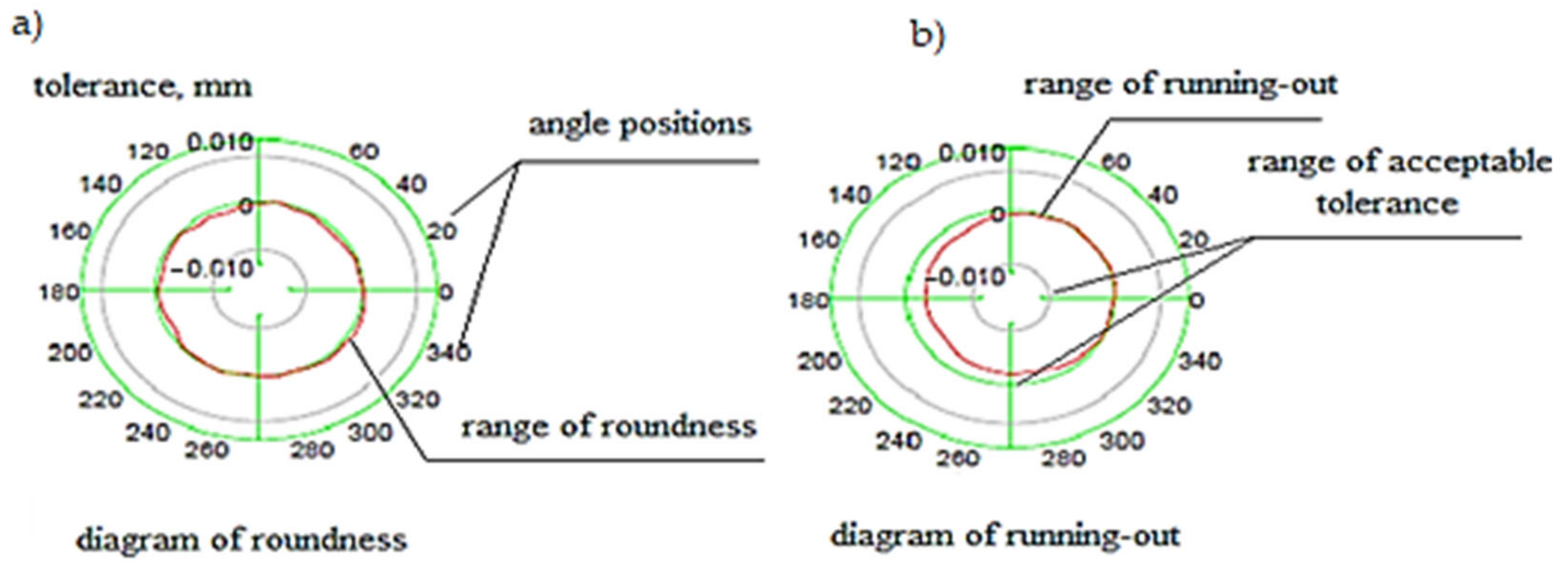
3.2. Quantitative Analysis of Roller Wear
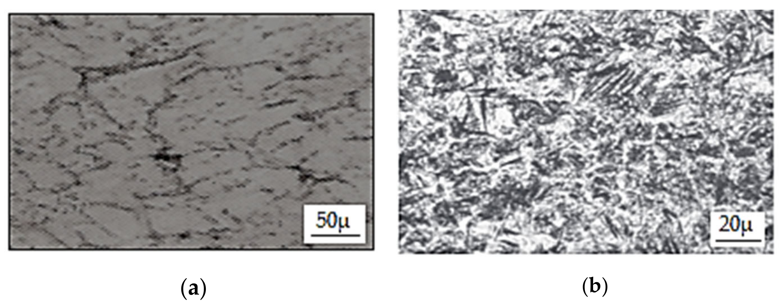
3.3. Hardness Measurements of HSS Sample
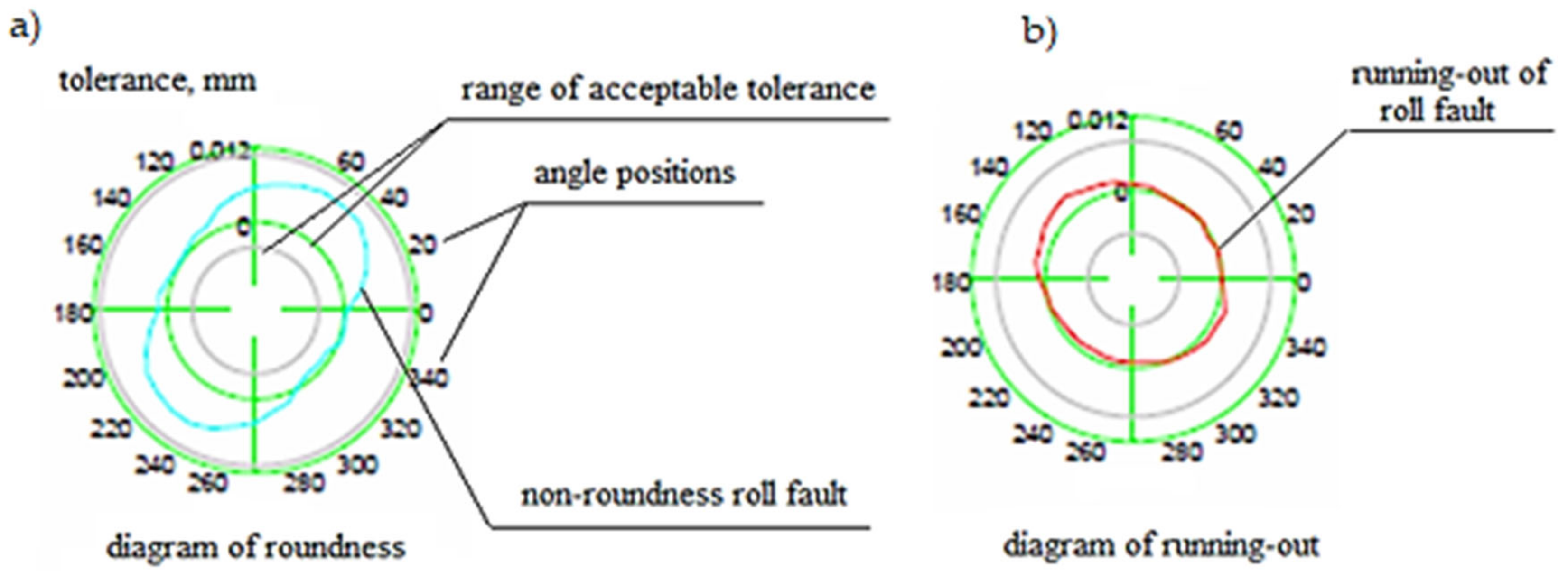
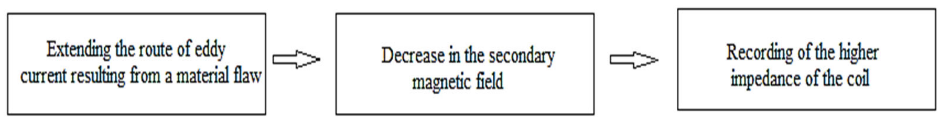
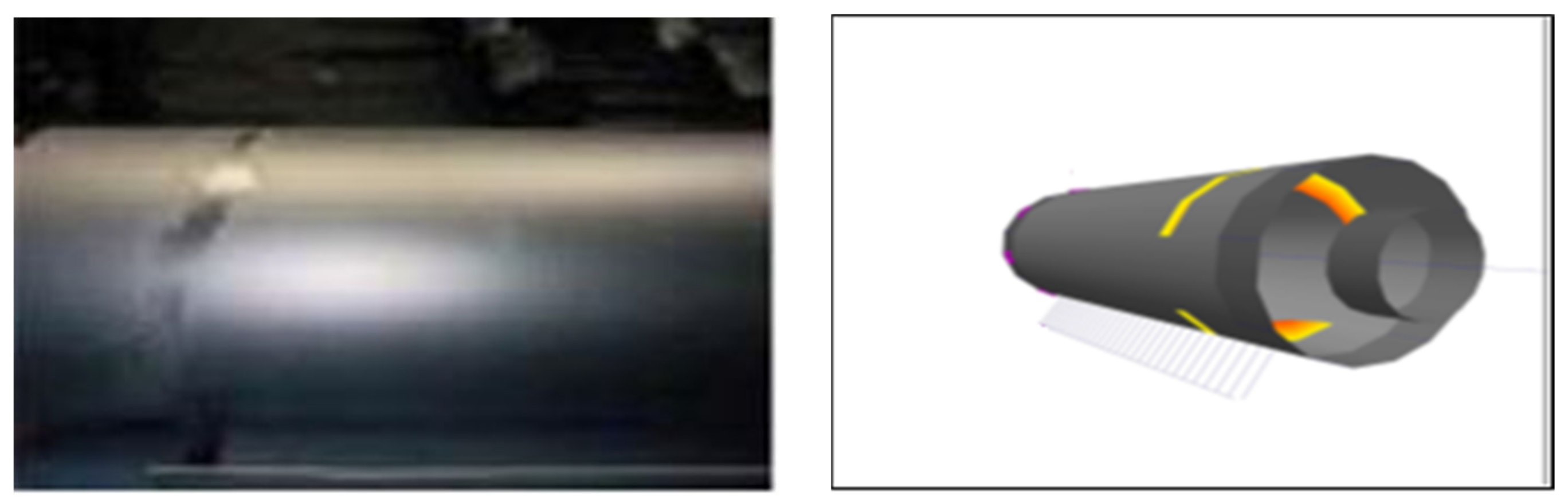
3.4. The Principle of Using the Effect of Eddy Currents in Non-Destructive Testing of Materials
4. Results and Discussion
4.1. Statistical Analysis of Roll Wear
- —distribution of a random variable.
- —computed significance level assessment.
- —no reason to reject the null hypothesis.
- —the null hypothesis should be rejected.
- α = 0.05—materiality level.
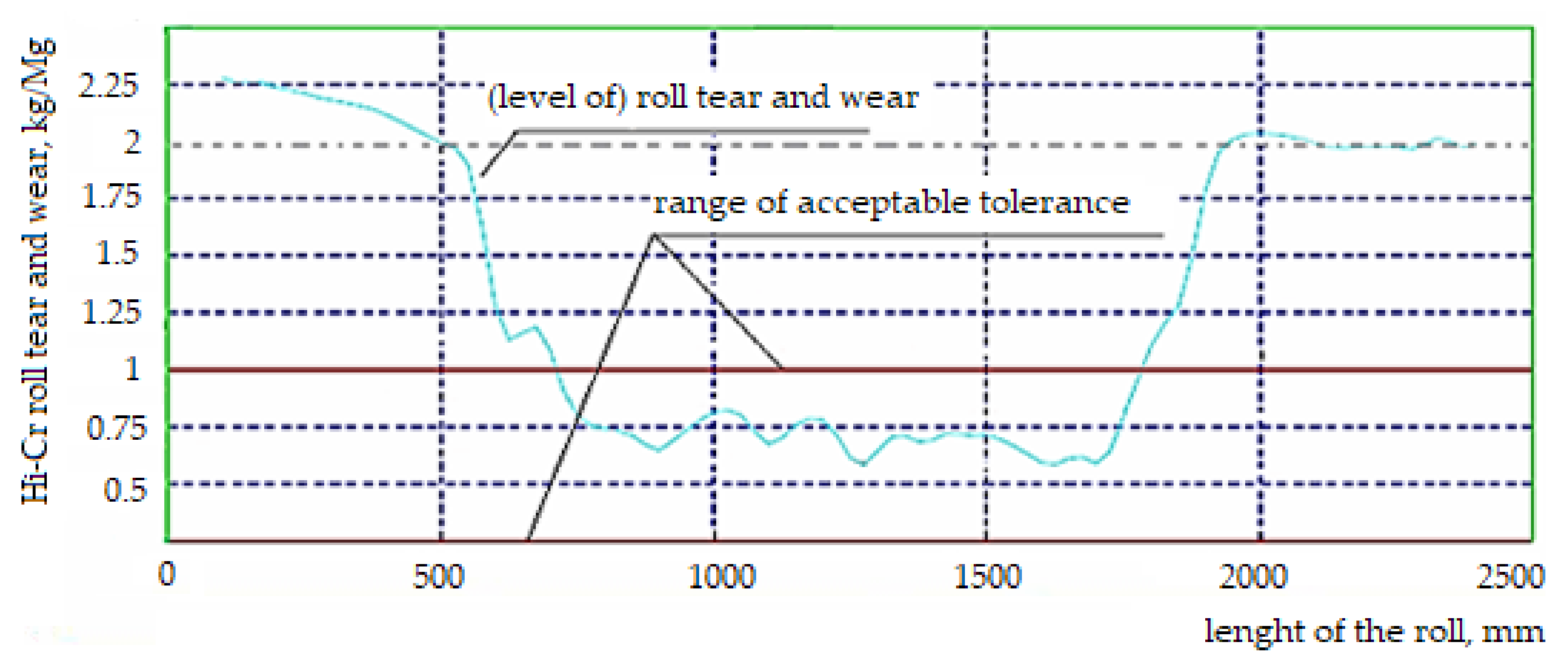
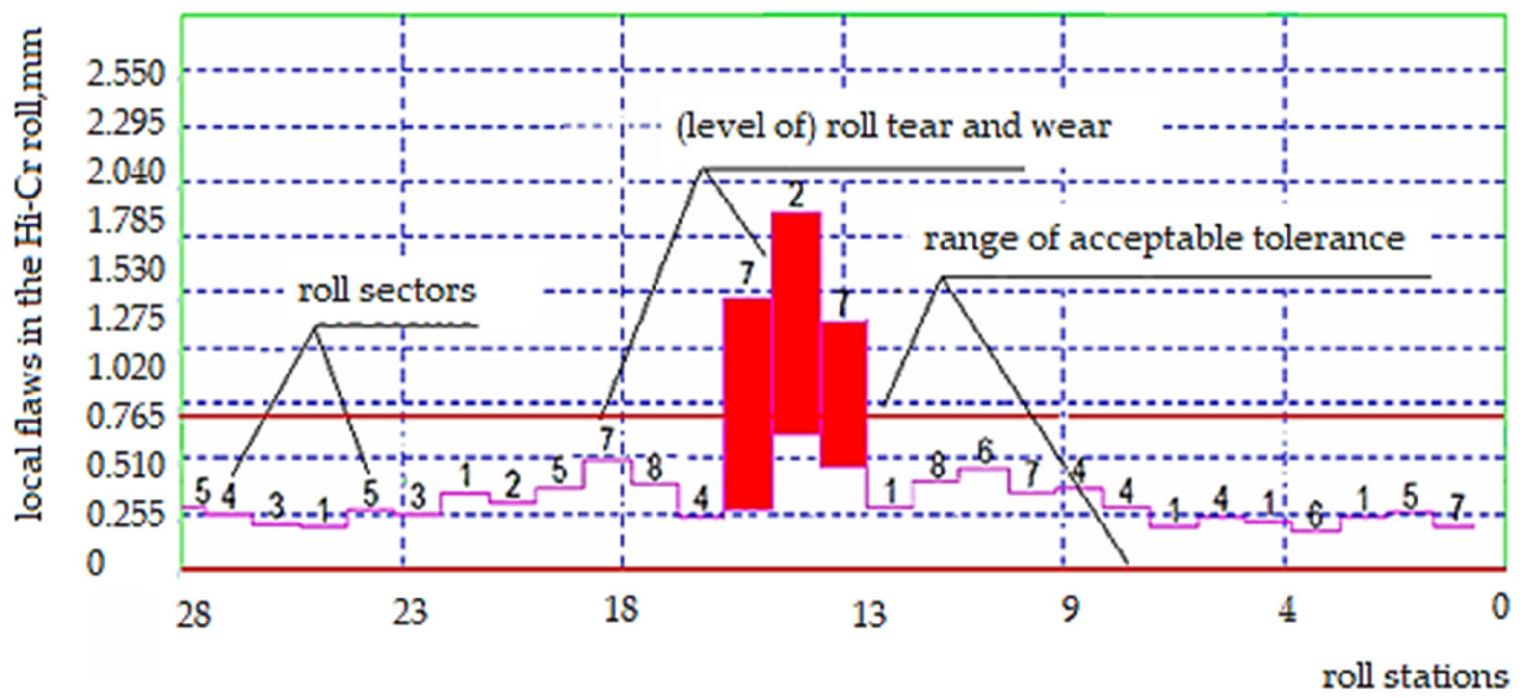
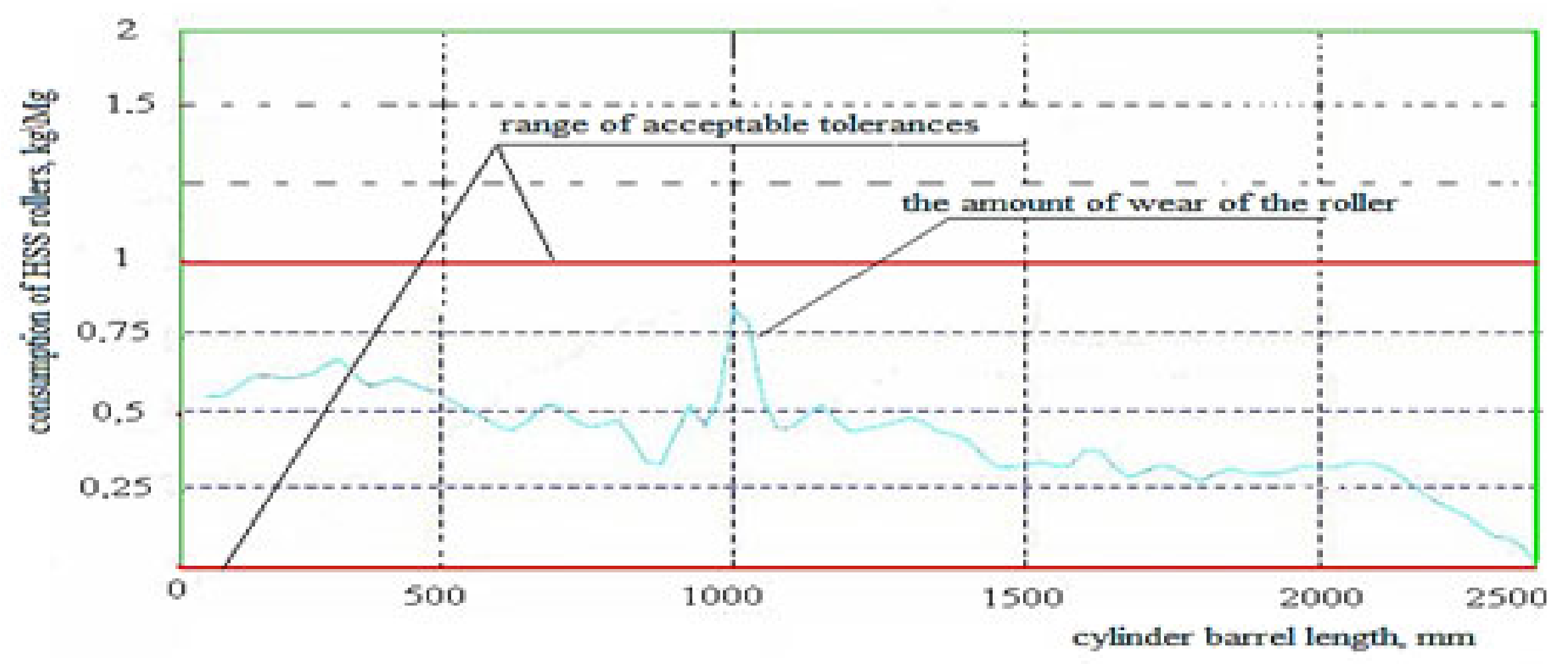
4.2. Quantitative Analysis of Roll Wear
4.3. Hardness Measurements of HSS Sample
4.4. The Principle of Using the Effect of Eddy Currents in Non-Destructive Testing of Materials
5. Conclusions
- The statistical method for determining the service life of working rolls indicated that their reconstruction is determined both by natural physical phenomena and, in about 10% of cases, by their improper use, mainly in frames F5 and F6 of the finishing set.
- Roll-wear indicators are of key importance for the construction of rolling campaigns and production schedules, decisively influencing the reduction of roll wear and costs and changeover times.
- Calculations made using the program: “Roll Grinding Management System” indicate the possibility of replacing the working rolls of high chromium cast iron Hi-Cr with HSS rollers in cages F5 and F6, which will contribute to an increase in the hardness of the rolls, a reduction in production costs and a decrease in the number of rebuilds.
- The operating life of HSS rolls is 14,000–20,000 Mg of rolled material per millimeter of wear on its surface in the radial direction, compared to 2000 Mg for rolls made of high chromium cast iron Hi-Cr.
- HSS type rolls show 80% less wear compared to high chromium rolls. The improvement of the durability of the roll, especially its hardness, wear resistance and suitable surface roughness, was influenced by the appropriate choice of material and mainly by the increase in the proportion of carbides and the appropriate structure of the material.
- The benefits of this work include: the determination of cost and energy relationships between individual profiles and steel grades in active production; the ability to track energy consumption and processing costs depending on the currently produced assortment; and the verification of market prices for individual grades and profiles of steel.
Author Contributions
Funding
Institutional Review Board Statement
Informed Consent Statement
Data Availability Statement
Conflicts of Interest
References
- Ryu, J.H.; Kwon, O.; Lee, P.J.; Kim, Y.M. Evaluation of the finishing roll surface deterioration at hot strip mill. ISIJ Int. 1992, 32, 1221–1223. [Google Scholar] [CrossRef]
- Simão, J.; Aspinwall, D. Hard chromium plating of EDT mill work rolls. J. Mater. Process. Technol. 1999, 92, 281–287. [Google Scholar] [CrossRef]
- Becker, E.; Ludema, K. A qualitative empirical model of cylinder bore wear. Wear 1999, 225, 387–404. [Google Scholar] [CrossRef]
- Li, G.; Li, X.; Wu, J. Study of the thermal fatigue crack initial life of h13 and h21 steels. J. Mater. Process. Technol. 1998, 74, 23–26. [Google Scholar] [CrossRef]
- Lima, L.G.; GonÇalves, A.; Braga, A.P.V.; Boccalini, M.; Souza, R.M. Coupled experimental-numerical analysis of Wear in hot-rolling Mills. In Proceedings of the 10th International Tooling Conference, Bratysława, Slovakia, 10–17 April 2016. [Google Scholar]
- Niekurzak, M. The Potential of Using Renewable Energy Sources in Poland Taking into Account the Economic and Ecological Conditions. Energies 2021, 14, 7525. [Google Scholar] [CrossRef]
- Niekurzak, M.; Mikulik, J. Modeling of Energy Consumption and Reduction of Pollutant Emissions in a Walking Beam Furnace Using the Expert Method—Case Study. Energies 2021, 14, 8099. [Google Scholar] [CrossRef]
- Niekurzak, M. Determining the Unit Values of the Allocation of Greenhouse Gas Emissions for the Production of Biofuels in the Life Cycle. Energies 2021, 14, 8394. [Google Scholar] [CrossRef]
- Wróblewski, P.; Niekurzak, M. Assessment of the Possibility of Using Various Types of Renewable Energy Sources Installations in Single-Family Buildings as Part of Saving Final Energy Consumption in Polish Conditions. Energies 2022, 15, 1329. [Google Scholar] [CrossRef]
- Kubińska-Jabcoń, E.; Kubiński, W.; Niekurzak, M. Analysis of the Economical, Ecological and Quality Advantages Consequent Resulting from Initiation of Technology Integrated in Metallurgy. J. Mech. Eng. Autom. 2015, 5, 549–553. [Google Scholar] [CrossRef] [Green Version]
- Kubińska-Jabcoń, E.; Niekurzak, M. Methods of limiting selected risk types in the municipal waste incineration plant. Manag. Econ. 2019, 20, 43–56. [Google Scholar] [CrossRef] [Green Version]
- Niekurzak, M.; Kubińska-Jabcoń, E. Analysis of the Return on Investment in Solar Collectors on the Example of a Household: The Case of Poland. Front. Energy Res. 2021, 9, 224. [Google Scholar] [CrossRef]
- Niekurzak, M. Analiza Możliwości Rozwoju i Wykorzystania Potencjału Biogazu Rolniczego na cele Energetyczne w Polsce, Nauka—Technika—Technologia: Seria Wydawnicza AGH, T.2; Wydawnictwa AGH: Kraków, Poland, 2021; pp. 135–148. ISBN 9788366727489. Available online: https://winntbg.bg.agh.edu.pl/skrypty4/0592/NTT_tom2_135.pdf (accessed on 4 March 2022).
- Jin, D.Q.; Hernandez, V. Integrated process model for the hot rolling of plain carbon steel. In Proceedings of the Second International Conference Modeling of Metal Rolling Processes, London, UK, 9–11 December 1996; pp. 6–58. [Google Scholar]
- Costa, H.; Hutchings, I. Some innovative surface texturing techniques for tribological purposes. Proc. Inst. Mech. Eng. Part J J. Eng. Tribol. 2015, 229, 429–448. [Google Scholar] [CrossRef] [Green Version]
- Persson, A.; Hogmark, S.; Bergström, J. Simulation and evaluation of thermal fatigue cracking of hot work tool steels. Int. J. Fatigue 2004, 26, 1095–1107. [Google Scholar] [CrossRef]
- Szota, P.; Mróz, S.; Stefanik, A.; Dyja, H. Numerical modelling of the working rolls wear during rods rolling process. Arch. Metall. Mater. 2011, 56, 495–501. [Google Scholar] [CrossRef] [Green Version]
- Lima, L.G. Experimental Analysis and Numerical Modelling of the Influence of the Oxidation on the Thermal Fatigue of Hot Rolling Rolls. Master’s Thesis, University of São Paulo, São Paulo, Brazil, 2018. [Google Scholar]
- Tseng, A.A.; Lin, F.H.; Gunderia, A.S.; Ni, D.S. Roll cooling and its relationship to roll life. Metall. Trans. A 1989, 20, 2305–2320. [Google Scholar] [CrossRef]
- Benasciutti, D.; Brusa, E.; Bazzaro, G. Finite elements prediction of thermal stresses in work roll of hot rolling Mills. Procedia Eng. 2010, 2, 707–716. [Google Scholar] [CrossRef] [Green Version]
- Elkoca, O. A study on the characteristics of electrical discharge textured skin pass mill work roll. Surf. Coat. Technol. 2008, 202, 2765–2774. [Google Scholar] [CrossRef]
- Pawelski, O.; Rasp, W.; Zwick, W.; Nettelbeck, H.; Steinhoff, I. The influence of different work-roll texturing systems on the development of surface structure in the temper rolling process of steel sheet used in the automotive industry. J. Mater. Process. Technol. 1994, 45, 215–222. [Google Scholar] [CrossRef]
- Serajzadeh, S. Effects of rolling parameters on work-roll temperature distribution in the hot rolling of steels. Int. J. Adv. Manuf. Technol. 2008, 35, 859–866. [Google Scholar] [CrossRef]
- Simão, J.; Aspinwall, D.; Wise, M.; El-Menshawy, M. Mill roll texturing using EDT. J. Mater. Process. Technol. 1994, 45, 207–214. [Google Scholar] [CrossRef]
- Spuzic, S.; Strafford, K.N.; Subramanian, C.; Savage, G. Wear of hot rolling mill rolls: An overview. Wear 1994, 176, 261–271. [Google Scholar] [CrossRef]
- Tseng, A.A. Thermal modeling of roll and strip interface in rolling processes: Part 1-review. Numer. Heat Transf. Part A Appl. 1999, 35, 115–133. [Google Scholar] [CrossRef]
- Vilaseca, M.; Pujante, J.; Ramírez, G.; Casellas, D. Investigation into adhesive wear of PVD coated and uncoated hot stamping production tools. Wear 2013, 308, 148–154. [Google Scholar] [CrossRef]
- Wright, B. Thermal Behavior of Work Rolls in the Hot Mill Rolling Process. Ph.D. Thesis, The University of Swansea, Swansea, UK, 2014. [Google Scholar]
- Maccagno, T.M.; Jonas, J.J.; Yue, S.; Mccrady, B.J.; Slobodian, R.; Deeks, D. Determination of recrystallization stop temperature from rolling mill logs and comparison with laboratory simulation results. ISIJ Int. 1994, 34, 917–922. [Google Scholar] [CrossRef]
- Mello, J.D.; Gonçalves, J.; Costa, H. Influence of surface texturing and hard chromium coating on the wear of steels used in cold rolling mill Rolls. Wear 2013, 302, 1295–1309. [Google Scholar] [CrossRef]
- Milan, J.; Carvalho, M.; Xavier, R.; Franco, S.; Mello, J. Effect of temperature, normal load and pre-oxidation on the sliding wear of multi-component ferrous alloys. Wear 2005, 259, 412–423. [Google Scholar] [CrossRef]
- Montmitonnet, P.; Delamare, F.; Rizoulieres, B. Transfer layer and friction in cold metal strip rolling processes. Wear 2000, 245, 125–135. [Google Scholar] [CrossRef]
- Park, J.Π.; Kim, C.K.; Leeb, S. Evaluation of thermal fatigue properties of hss roll materials. In Proceedings of the Metal Konference, Hradec nad Moravicí, Czech Republic, 20–22 May 2003. [Google Scholar]
- Costa, H.; Hutchings, I. Effects of die surface patterning on lubrication in strip drawing. J. Mater. Process. Technol. 2009, 209, 1175–1180. [Google Scholar] [CrossRef]
- Roberts, W.L. Hot rolling of steel. Manuf. Eng. Mater. Process 1983, 10, 779–783. [Google Scholar]
- Labiapari, W.; Alcântara, C.; Costa, H.; Mello, J. Wear debris generation during cold rolling of stainless steels. J. Mater. Process. Technol. 2015, 223, 164–170. [Google Scholar] [CrossRef]
- Ye, X. Thermal Crown Development in Hot Strip Mill Work Rolls and the Role of Spray Cooling. Master’s Thesis, The University of British Columbia, Vancouver, BC, Canada, 1990. [Google Scholar]
- Dymek, W. Internal Materials of HOT Rolling Mills; AlcellorMittal: Kraków, Poland, 2021; Unpublished. [Google Scholar]
- Fletcher, D.; Kapoor, A.; Steinhoff, K.; Schuleit, N. Wear behaviour and surface form evolution of a novel titanium carbide implanted surface under lubricated conditions. Proc. Inst. Mech. Eng. Part J J. Eng. Tribol. 2000, 214, 597–610. [Google Scholar] [CrossRef]
- Krzyzanowski, M.; Beynon, J.H. Interfacial heat transfer during hot metal forming operations assuming scale failure effects. Mater. Sci. Technol. 2016, 32, 407–417. [Google Scholar] [CrossRef]
- Deltombe, R.; Dubar, M.; Dubois, A.; Dubar, L. A new methodology to analyse iron fines during steel cold rolling processes. Wear 2003, 254, 211–221. [Google Scholar] [CrossRef]
- Hilgenberg, K.; Steinhoff, K. Texturing of skin-pass rolls by pulsed laser dispersing. J. Mater. Process. Technol. 2015, 225, 84–92. [Google Scholar] [CrossRef]
- Huart, S.; Dubar, M.; Deltombe, R.; Dubois, A.; Dubar, L. Asperity deformation, lubricant trapping and iron fines formation mechanism in cold rolling processes. Wear 2004, 257, 471–480. [Google Scholar] [CrossRef]
- Le Roux, S.; Medjedoub, F.; Dour, G.; RÉzaÏ-Aria, F. Role of heat-flux density and mechanical loading on the microscopic heat-checking of high temperature tool steels under thermal fatigue experiments. Int. J. Fatigue 2013, 51, 15–25. [Google Scholar] [CrossRef]


| Elemental Content, % | |||||||||
|---|---|---|---|---|---|---|---|---|---|
| C | Mn | Si | P | S | Cr | Ni | Mo | W | V |
| 1.15 | 0.96 | 0.87 | 0.05 | 0.02 | 2.6 | 1.3 | 4.2 | 4.1 | 3.9 |
| Grade of Material | Cage Number | Average | Standard Deviation | N | Notes | ||
|---|---|---|---|---|---|---|---|
| S235 JR | RM | 727.57 | 315.00 | 15 | 9.488 | 1.494 | no reason to reject the null hypothesis |
| F1 | 2285.19 | 1047.64 | 21 | 5.991 | 0.844 | no reason to reject the null hypothesis | |
| F2 | 1628.36 | 526.00 | 30 | 7.815 | 6.138 | no reason to reject the null hypothesis | |
| F3 | 1674.58 | 415.29 | 79 | 9.488 | 8.670 | no reason to reject the null hypothesis | |
| F4 | 695.34 | 354.72 | 72 | 9.488 | 3.367 | no reason to reject the null hypothesis | |
| F5 | 543.63 | 138.00 | 173 | 10.068 | 46.900 | the null hypothesis should be rejected | |
| F6 | 526.50 | 109.00 | 169 | 11.070 | 15.841 | the null hypothesis should be rejected |
| Roll Type | Material | Consumption for the Year | ||
|---|---|---|---|---|
| 2020 | 2021 | |||
| Pre-assembly cage rolls | ||||
| Thrust rollers | ø 1600 × 2500 | Steel 3% Cr | 0.06 | 0.040 |
| ø 1600 × 2500 | Cast steel | 0.353 | 0.361 | |
| ∑ for resistance rollers | 0.413 | 0.401 | ||
| Work rollers | ø 1100 | ICDP | 0.105 | 0.157 |
| ø 1250 × 2500 | EICDP | 0.353 | 0.361 | |
| ∑ for work rollers | 0.458 | 0.518 | ||
| Finishing unit cage rollers | ||||
| Cage F1–F3 | ø 825 × 2500 | ICDP | 0.557 | 0.538 |
| Cage F1–F3 | ø 825 × 2500 | ICDP | 0.463 | 0.473 |
| Cage F4 | ø 825 × 2500 | EICDP | 0.152 | 0.191 |
| Cage F4 | ø 825 × 2500 | ICDP | 1.056 | 1.092 |
| Cage F5 i F6 | ø 730 × 2500 | Hi-Cr | 1.982 | 1.961 |
| Cage F5 i F6 | ø 730 × 2500 | Hi-Cr | 2.011 | 2.197 |
| ∑ for working and back-up rollers | 6.221 | 6.452 | ||
| ∑ for work rolls and back-up rolls of the entire rolling assembly rolling mill unit | 7.092 | 7.371 | ||
| Type of Heat Treatment | Hardness | ||
|---|---|---|---|
| HB | HRC | HSh | |
| Condition after casting | 588–618 | 60 | 82–83 |
| Softened 700 °C/8 h | 267–278 | - | 55–58 |
| Hardened 1050–1080 °C | - | 61–63 | 77–80 |
| Tempering once 580–600 °C/3 h | - | 58–60 | 70–73 |
| Double tempering 580–600 °C/3 h | - | 50–52 | 71–75 |
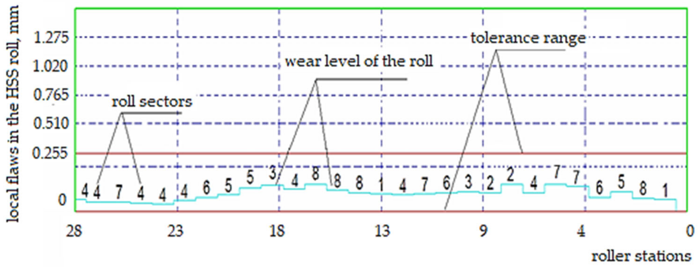
| Roll Sectors | Roller Stations | |||||||||||||
|---|---|---|---|---|---|---|---|---|---|---|---|---|---|---|
| 1 | 2 | 3 | 4 | 5 | 6 | 7 | 8 | 9 | 10 | 11 | 12 | 13 | 14 | |
| Roll Fracture Defect | ||||||||||||||
| 8 | 0.08 | 0.10 | 0.10 | 0.09 | 0.10 | 0.13 | 0.09 | 0.15 | 0.19 | 0.25 | 0.17 | 0.18 | 0.14 | 0.29 |
| 7 | 0.12 | 0.12 | 0.10 | 0.06 | 0.10 | 0.12 | 0.11 | 0.14 | 0.18 | 0.27 | 0.22 | 0.21 | 0.13 | 0.60 |
| 6 | 0.09 | 0.11 | 0.06 | 0.09 | 0.10 | 0.11 | 0.10 | 0.13 | 0.22 | 0.23 | 0.27 | 0.16 | 0.11 | 0.22 |
| 5 | 0.10 | 0.10 | 0.08 | 0.08 | 0.10 | 0.14 | 0.11 | 0.12 | 0.17 | 0.20 | 0.18 | 0.11 | 0.21 | 0.18 |
| 4 | 0.10 | 0.10 | 0.09 | 0.09 | 0.11 | 0.11 | 0.11 | 0.15 | 0.21 | 0.16 | 0.15 | 0.12 | 0.14 | 0.14 |
| 3 | 0.07 | 0.09 | 0.10 | 0.08 | 0.11 | 0.09 | 0.13 | 0.14 | 0.19 | 0.28 | 0.18 | 0.13 | 0.14 | 0.13 |
| 2 | 0.08 | 0.06 | 0.11 | 0.06 | 0.10 | 0.08 | 0.09 | 0.13 | 0.20 | 0.22 | 0.18 | 0.12 | 0.19 | 0.40 |
| 1 | 0.09 | 0.08 | 0.10 | 0.10 | 0.12 | 0.09 | 0.09 | 0.14 | 0.19 | 0.22 | 0.17 | 0.17 | 0.13 | 0.24 |
| Roll Sectors | Roller Stations | |||||||||||||
| 15 | 16 | 17 | 18 | 19 | 20 | 21 | 22 | 23 | 24 | 25 | 26 | 27 | 28 | |
| Roll Fracture Defect | ||||||||||||||
| 8 | 0.13 | 0.43 | 0.16 | 0.20 | 0.22 | 0.17 | 0.11 | 0.06 | 0.11 | 0.09 | 0.10 | 0.10 | 0.09 | 0.12 |
| 7 | 0.23 | 0.27 | 0.14 | 0.25 | 0.25 | 0.17 | 0.09 | 0.07 | 0.07 | 0.09 | 0.09 | 0.09 | 0.06 | 0.11 |
| 6 | 0.48 | 0.16 | 0.16 | 0.17 | 0.23 | 0.19 | 0.13 | 0.08 | 0.07 | 0.08 | 0.08 | 0.07 | 0.05 | 0.14 |
| 5 | 0.11 | 0.14 | 0.15 | 0.14 | 0.20 | 0.17 | 0.13 | 0.10 | 0.10 | 0.11 | 0.09 | 0.08 | 0.11 | 0.13 |
| 4 | 0.13 | 0.15 | 0.16 | 0.17 | 0.21 | 0.19 | 0.18 | 0.22 | 0.13 | 0.09 | 0.08 | 0.09 | 0.14 | 0.07 |
| 3 | 0.29 | 0.16 | 0.12 | 0.16 | 0.21 | 0.18 | 0.13 | 0.10 | 0.09 | 0.08 | 0.06 | 0.10 | 0.08 | 0.08 |
| 2 | 0.52 | 0.21 | 0.16 | 0.19 | 0.23 | 0.16 | 0.13 | 0.09 | 0.09 | 0.09 | 0.09 | 0.11 | 0.10 | 0.10 |
| 1 | 0.14 | 0.16 | 0.18 | 0.18 | 0.21 | 0.21 | 0.11 | 0.19 | 0.08 | 0.10 | 0.09 | 0.09 | 0.08 | 0.12 |
| Roll Sectors | Roller Stations | |||||||||||||
|---|---|---|---|---|---|---|---|---|---|---|---|---|---|---|
| 1 | 2 | 3 | 4 | 5 | 6 | 7 | 8 | 9 | 10 | 11 | 12 | 13 | 14 | |
| Roll Fracture Defect | ||||||||||||||
| 8 | 0.19 | 0.18 | 0.13 | 0.18 | 0.20 | 0.11 | 0.19 | 0.12 | 0.15 | 0.19 | 0.11 | 0.08 | 0.17 | 0.16 |
| 7 | 0.18 | 0.17 | 0.14 | 0.18 | 0.52 | 0.19 | 0.18 | 0.09 | 0.13 | 0.17 | 0.17 | 0.11 | 0.15 | 0.11 |
| 6 | 0.16 | 0.11 | 0.18 | 0.17 | 0.21 | 0.18 | 0.19 | 0.11 | 0.16 | 0.15 | 0.19 | 0.16 | 0.11 | 0.15 |
| 5 | 0.11 | 0.13 | 0.17 | 0.18 | 0.24 | 0.17 | 0.18 | 0.16 | 0.17 | 0.12 | 0.21 | 0.17 | 0.18 | 0.17 |
| 4 | 0.12 | 0.17 | 0.15 | 0.15 | 0.11 | 0.15 | 0.15 | 0.17 | 0.11 | 0.18 | 0.19 | 0.15 | 0.14 | 0.13 |
| 3 | 0.10 | 0.15 | 0.09 | 0.11 | 0.17 | 0.19 | 0.16 | 0.17 | 0.10 | 0.16 | 0.17 | 0.11 | 0.16 | 0.11 |
| 2 | 0.12 | 0.15 | 0.05 | 0.16 | 0.23 | 0.11 | 0.14 | 0.19 | 0.08 | 0.14 | 0.14 | 0.13 | 0.14 | 0.15 |
| 1 | 0.13 | 0.18 | 0.11 | 0.13 | 0.22 | 0.12 | 0.16 | 0.19 | 0.11 | 0.11 | 0.10 | 0.09 | 0.12 | 0.14 |
| Parameters | Roll Material | |
|---|---|---|
| High Chrome Cast Iron Hi-Cr Type | High Speed Steel HSS Type | |
| Hardness, HSh | 56–64 | 78–81 |
| Structure | martensitic containing 25–30% carbide M7C3 | martensitic containing 40–55% carbide: MC, M7C, M2C |
| Application | the last cages of the rolling assembly | all rolling cages |
| Number of realized rolling campaigns in one roll development | 1 | 7–8 |
| Persistence, Mg | 2000–3000 | 14,000–20,000 |
| Mill yield, % | 94.50 | 98.50 |
| Roller wear, kg/Mg | 2.20 | 0.64 |
| Electricity consumption, kWh/Mg | 92 | 71 |
| Water consumption for cooling, m3/Mg | 1.23 | 0.84 |
Publisher’s Note: MDPI stays neutral with regard to jurisdictional claims in published maps and institutional affiliations. |
© 2022 by the authors. Licensee MDPI, Basel, Switzerland. This article is an open access article distributed under the terms and conditions of the Creative Commons Attribution (CC BY) license (https://creativecommons.org/licenses/by/4.0/).
Share and Cite
Niekurzak, M.; Kubińska-Jabcoń, E. Assessment of the Impact of Wear of the Working Surface of Rolls on the Reduction of Energy and Environmental Demand for the Production of Flat Products: Methodological Approach. Materials 2022, 15, 2334. https://doi.org/10.3390/ma15062334
Niekurzak M, Kubińska-Jabcoń E. Assessment of the Impact of Wear of the Working Surface of Rolls on the Reduction of Energy and Environmental Demand for the Production of Flat Products: Methodological Approach. Materials. 2022; 15(6):2334. https://doi.org/10.3390/ma15062334
Chicago/Turabian StyleNiekurzak, Mariusz, and Ewa Kubińska-Jabcoń. 2022. "Assessment of the Impact of Wear of the Working Surface of Rolls on the Reduction of Energy and Environmental Demand for the Production of Flat Products: Methodological Approach" Materials 15, no. 6: 2334. https://doi.org/10.3390/ma15062334
APA StyleNiekurzak, M., & Kubińska-Jabcoń, E. (2022). Assessment of the Impact of Wear of the Working Surface of Rolls on the Reduction of Energy and Environmental Demand for the Production of Flat Products: Methodological Approach. Materials, 15(6), 2334. https://doi.org/10.3390/ma15062334