3.1. Influence of Flow Rate and Composition of the Initial Gas Mixture
It is known that ammonia on iron catalysts can dissociate at atmospheric pressure already at temperatures of 300–350 °C. Hydrocarbon gases under these conditions remain practically inert and begin to dissociate at a noticeable rate at temperatures above 600 °C; therefore, it is proposed to use propane as a carbon-containing precursor.
In order to maintain the ammonia concentration under the synthesis conditions at a sufficiently high level, it is necessary to reduce the residence time of the reaction medium in the reactor by increasing its flow rate and lowering the temperature in the reactor.
As can be seen from the results in
Table 1, at a temperature in the reactor of 800 °C and a change in the mole flow of pure ammonia at the inlet to the reactor from 18.7 to 37.3 kmole/s, the mole flow of ammonia at the outlet remains practically unchanged. The result obtained indicates that in the studied range of mole flow rates in the outgoing mixture, an equilibrium concentration of unreacted ammonia is established, the level of which is determined by the temperature in the reactor. As the temperature in the reactor decreases, the flow rate and the equilibrium concentration of ammonia under stationary conditions increase.
We concluded that it is not advisable to increase the ammonia concentration at the reactor outlet by reducing the contact time (or, which is also an increase in the linear velocity), since this can lead to catalyst carryover from the reactor and may be accompanied by an unsustainable increase in the consumption of raw materials. Secondly, as can be seen from the table, it is more rational to reduce the temperature in the reactor.
For the synthesis of carbon nanotubes, the value of 26/1 kmol/s (200 mL/min) was chosen as the optimal flow rate of the initial mixture of propane and ammonia, while the synthesis of the carbon material was carried out at different ammonia contents in the initial mixture (C3H8/NH3, vol%): 100; 25:75; 50:50; 75:25; 90:10. The initial temperature for synthesis was chosen as 650 °C.
In order to establish the dependence of the amount of nitrogen introduced into CNTs on the different compositions of the initial gas mixture, as well as to determine the electronic state of atoms on the surface of the material under study, the obtained samples were investigated by X-ray photoelectron spectroscopy.
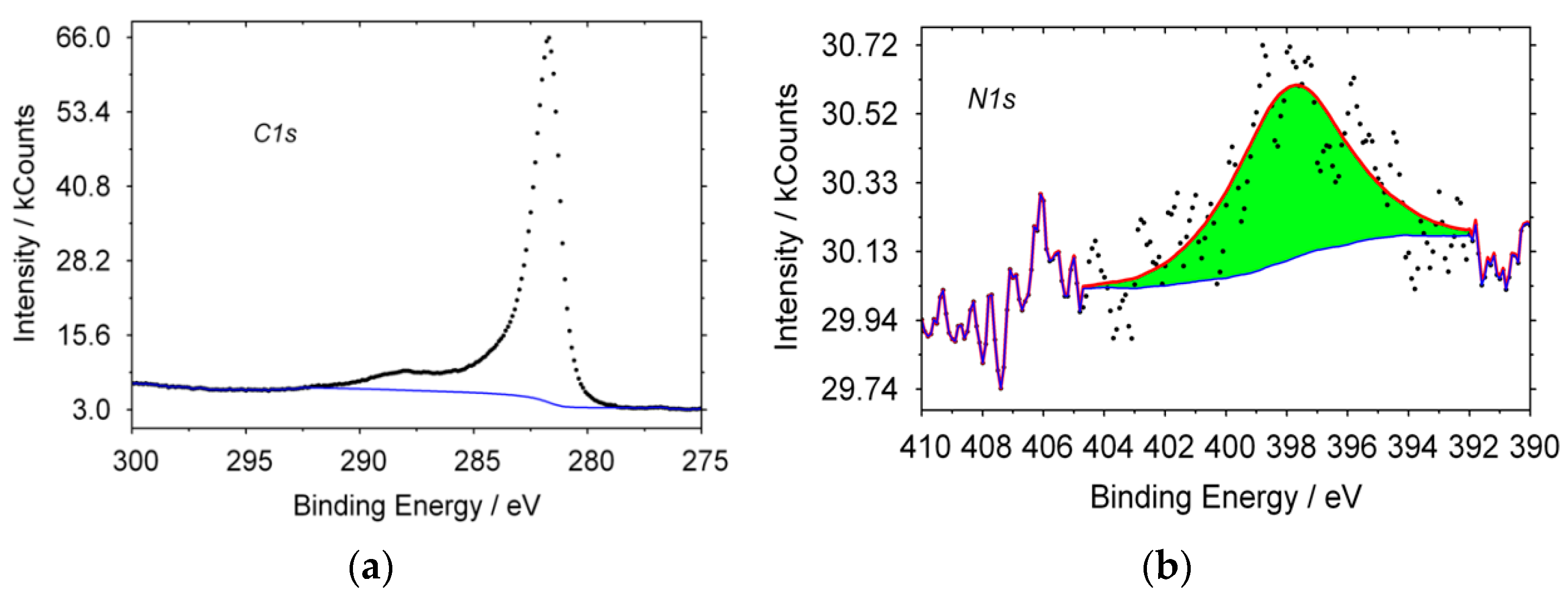
In
Figure 1, the typical XPS spectra of CNT, obtained from propane are shown. For carbon, the line shape of the spectrum has a maximum with E = 284.6 eV, which is typical for sp
2 hybridization carbon structures. A characteristic peak for nitrogen is observed; in a pyridine-like (398.8 eV) state, other forms of nitrogen are absent. The formation of a product containing nitrogen in its structure could occur only from a mixture of gases that was formed when nitrogen was supplied to the reactor during its heating or cooling. Therefore, N
2 can also be a nitrogen precursor gas, under the given synthesis conditions.
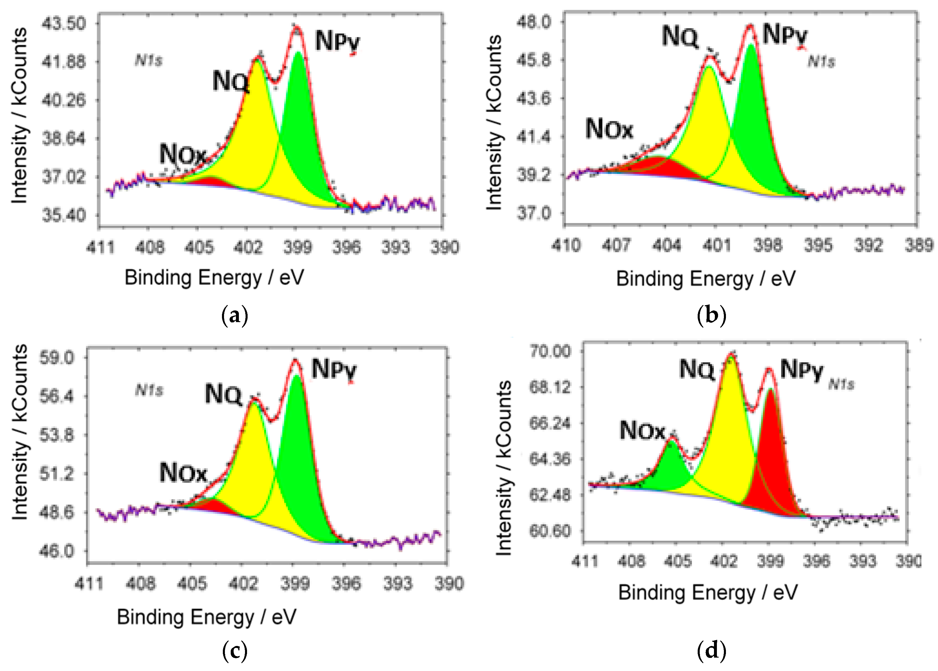
XPS spectra (N
1s) of samples with different ammonia content in the initial gas mixture are shown in
Figure 2. Characteristic peaks of different state of nitrogen are observed in all investigated samples: in the pyridine-like (N
Py, 398.8 eV), graphite-like (N
Q 401.7 eV) states and oxidized forms of nitrogen (N
Ox 405.6 eV).
The content of the different states of nitrogen, carbon and oxygen in synthesized samples are presented in
Table 2.
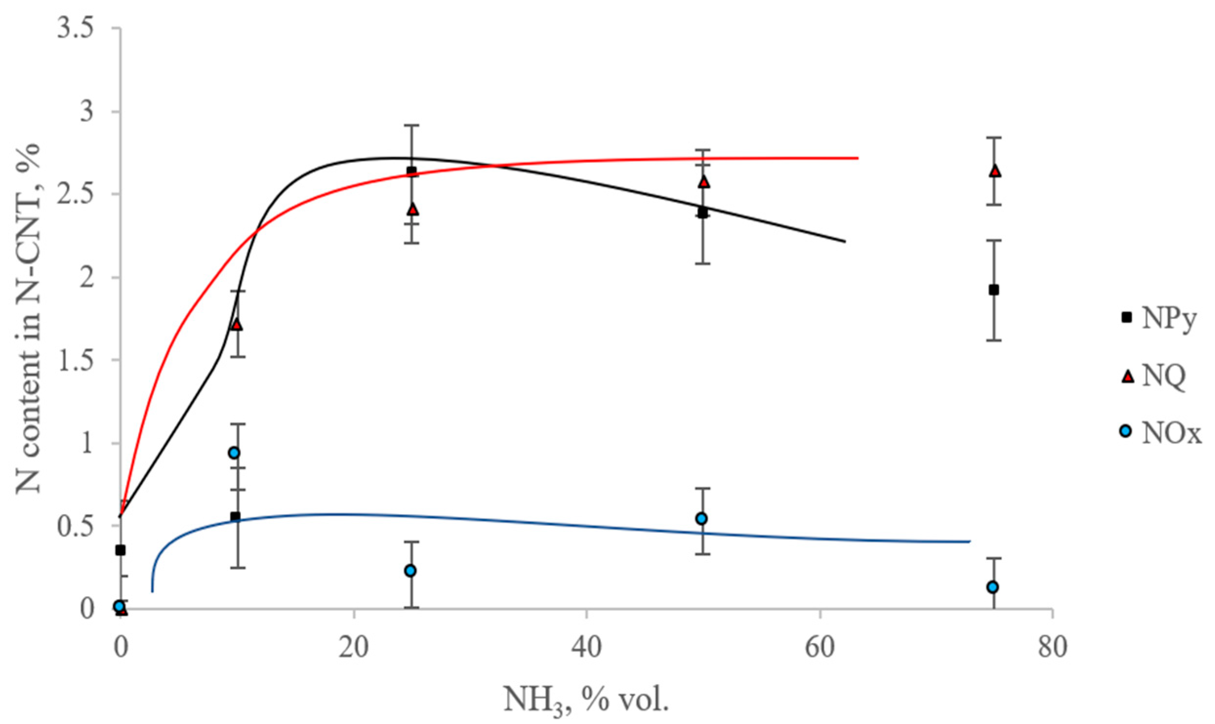
Figure 3 and
Figure 4 show the dependences of the content of total nitrogen and various forms of nitrogen on the initial content of ammonia in the reaction mixture.
From
Figure 3 and
Figure 4 it can be seen that with an increase in the ammonia content in the initial gas mixture, the total nitrogen content in the samples first increases to the maximum nitrogen content in the sample, synthesized from a mixture of C
3H
8/NH
3 = (50/50%), and then decreases. In this case, the maximum content of the pyridine-like form of nitrogen is observed in the sample, which is synthesized from a mixture of C
3H
8/NH
3 (75/25%). A graphite-like form is seen in the sample C
3H
8/NH
3 (25/75%). The smallest content of oxidized forms of nitrogen contains the N-CNT, synthesized using C
3H
8/NH
3 (25/75%).
According to the literature, the maximum nitrogen content in a doped carbon material can reach about 10%; however, a high nitrogen content is not always justified from the point of view of further use, including as catalyst supports [
6,
8,
31]. Significant incorporation of nitrogen into the structure of carbon nanotubes occurs at a high level of ammonia; however, at a concentration of more than 50%, the process of nitrogen doping slows down, and such an effect of the ammonia content may be due to the different mechanism of formation of nitrogen-doped structures [
8]. To establish the mechanism, first of all, it is required to trace which phase transformations the catalyst undergoes. We assume that nitrides or carbonitrides are formed during CVD-synthesis, and the ammonia concentration has a direct effect on this process.
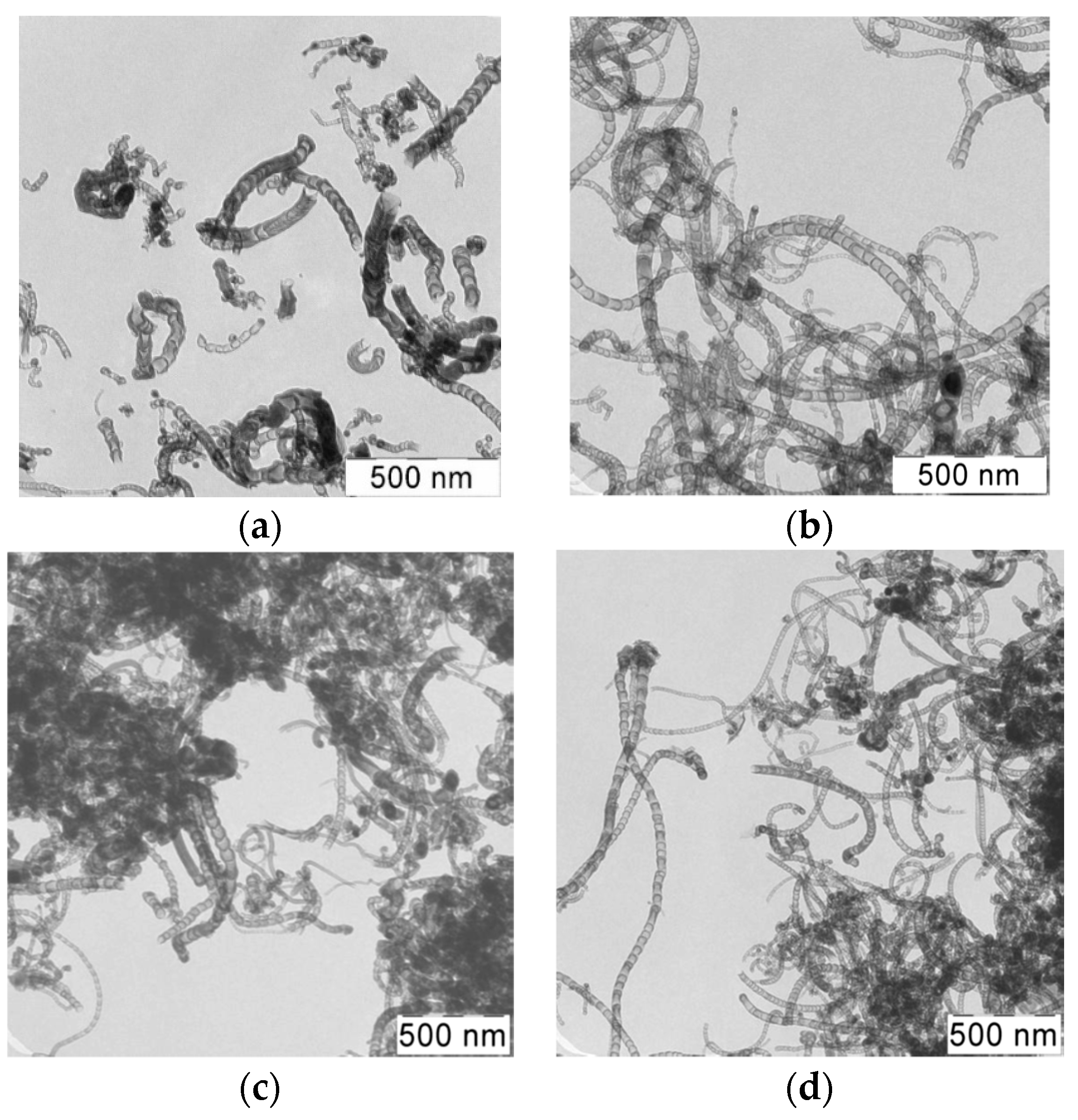
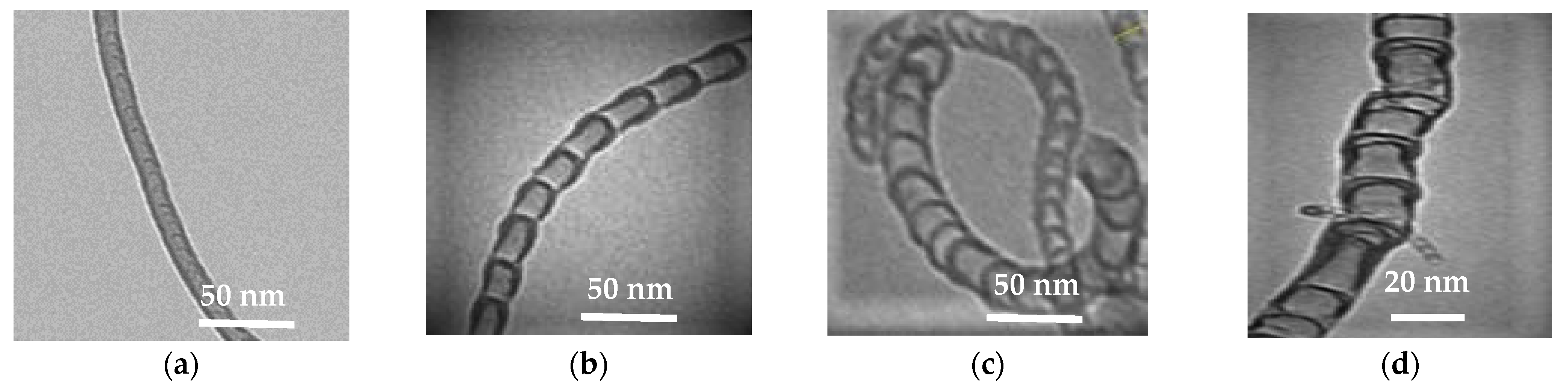
Figure 5 shows TEM-images of samples of synthesized N-CNT using a gas mixture with a different ratio of C
3H
8/NH
3 at a temperature of 650 °C.
As can be seen from the images, the synthesized product is presented by different structures CNTs. There are several types of morphological structures found in the obtained products of nitrogen-doped carbon materials, including multiwalled carbon nanotubes (MWCNT), bamboo-like structures, spherical and irregular sections [
13,
25]. These types of structures are presented on
Figure 6.
From a review of the literature, we can conclude that the nanotubes with bamboo-like, spherical and irregular structures (
Figure 6b–d) are most likely nitrogen-doped carbon materials [
13,
25].
Based on the results of transmission electron microscopy of the samples,
Table 3 contains the percentage of different type structures in samples, synthesized in the presence of NH
3 content, and the values of predominant inner and outer diameters.
It can be seen that the composition of the initial gas mixture affects the morphology, at various ratios of initial gases, certain morphological structures prevail in the product.
With an increase in the content of ammonia in the mixture, there is an increase in the content of bamboo-like structures and a decrease in the content of irregular structures. For the sample synthesized from C3H8/NH3 (50/50%) mixture, the quantitative ratio of all the observed structures occupies an intermediate position with respect to other samples. It also corresponds to the highest total content of fibers with bamboo-like and spherical sections (81.8%).
The values of the predominant outer and inner diameters lie in the range from 31 to 24 and from 24 to 15, respectively. Despite the change in the fractional composition of the carbon material with a change in the initial content of ammonia, no significant difference in the sizes of nanotubes is observed.
3.2. Temperature Effect
The choice of synthesis temperature is based on the dependence of the content of nitrogen atoms embedded in the CNT structure. For this purpose, several CNT samples were synthesized in an ammonium-propane mixture at several temperatures at a constant ratio of ammonia and propane in the initial gas mixture (50/50%). The
Table 4 shows the values of product yield and residual catalyst content.
An important parameter in the synthesis of CNTs is their yield, which is determined by the ratio of the mass of the formed product to the mass of the initial catalyst. As can be seen from the presented data, with an increase in the synthesis temperature, an increase in the yield of N-CNTs is observed; moreover, the increase in initial ammonia content leads to the decrease of the N-CNT yield.
It is known that the amount of nitrogen contained in CNTs is affected by the conditions of synthesis [
22,
31].
Table 5 contains the results of XPS-analysis for samples, synthesized at different temperature and constant gas mixture (50/50%).
From the data presented in
Table 5, it can be seen that with an increase in the process temperature from 650 °C to 800 °C, a general decrease in the nitrogen content in N-CNTs is observed. This result may be due to a decrease in the concentration of ammonia in the gas phase.
It can be also seen that a decrease in temperature promotes the synthesis of materials containing non-oxidized forms of nitrogen incorporated into the carbon structure. An increase in the synthesis temperature leads to the appearance of oxidized forms of nitrogen. At temperatures of 700 °C and 750 °C, nitrogen in the tubes is in two states: pyridine-like and graphite-like, while the content of nitrogen in the graphite-like state is higher than in the pyridine-like state at any synthesis temperature. With an increase in temperature to 800 °C, a third form of nitrogen appears: oxidized. In addition, oxygen was found in the product, the content of which decreases with increasing synthesis temperature. One of the reasons for the appearance of oxygen in the samples, is residual catalyst in N-CNT, which components can be only partially reduced to a metallic state.
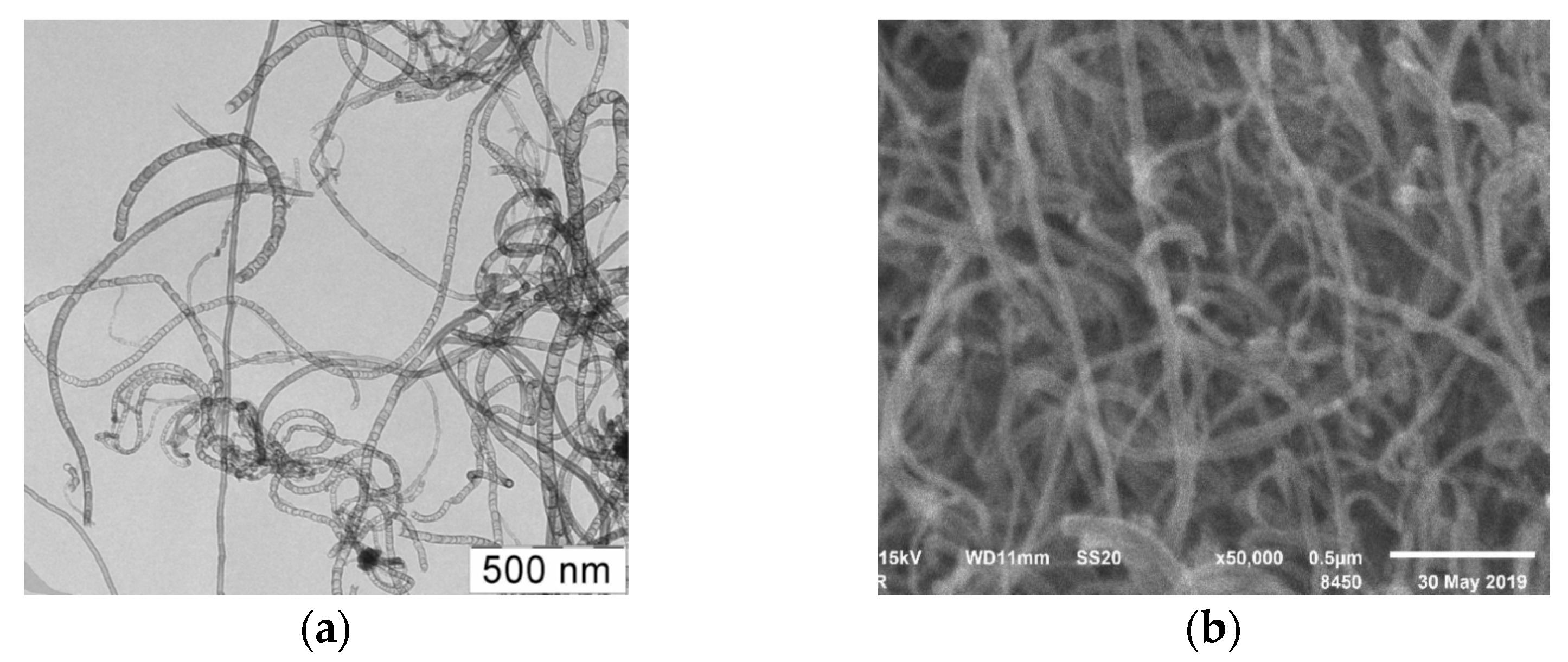
Figure 7 shows TEM and SEM-images of samples of synthesized N-CNT using a C
3H
8/NH
3 (50/50%) gas mixture at a temperature 800 °C.
As can be seen from the presented figures, the carbon nanomaterial is presented by nanotubes of various morphologies, including multiwalled carbon nanotubes (MWCNT), bamboo-like structures, spherical and irregular sections, similar to the material synthesized at 650 °C.
Based on the obtained TEM-images, the predominant inner and outer diameters and percentage of different morphological structures of nitrogen-doped CNTs were calculated. These results are presented in the
Table 6.
It can be seen that the synthesis temperature affects the fractional composition of the resulting carbon material. With an increase in temperature, the content of bamboo-like and irregular structures increases, and the content of structures with spherical sections decreases. Based on the fact that only bamboo-like and spherical structures can be attributed to nitrogen-doped carbon nanotubes, the optimal temperature range for synthesis is 650 °C.
The values of the predominant outer and inner diameters lie in the range from 26 to 20 and from 16 to 8, respectively. There is no significant change in the particle size with an increase in the synthesis temperature.
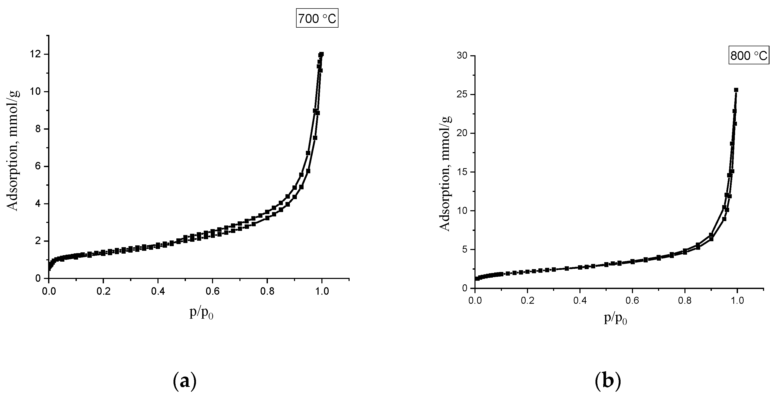
For investigating of doped N-CNT porous structure samples o with a total nitrogen content (N)
total of 4.6 and 2.3%, obtained at temperatures of 700 and 800 °C, were studied using low-temperature nitrogen adsorption, which are presented on the
Figure 8.
The isotherms refer to Type II according to the De-Boer classification, and indicates the occurrence of polymolecular adsorption. Based on the obtained isotherms, the main characteristics of the porous structure of were calculated: specific surface area, pore volume, and predominant pore diameter. The obtained values are shown in
Table 7.
As can be seen from the presented data, the studied samples of carbon material have mesoporous structure, the specific surface of which is 113 and 215 m2/g. The pore volume of the samples is 0.4 and 1.2 cm3/g, the main contribution to which is made by mesopores, which are formed due to the interparticle volume between carbon nanotubes. Mesopore size distribution calculated BJH method (Barrett–Joyner–Halenda) shows that the predominant pore size is about 3–4 nm.
An increase in the surface area and pore volume may be associated with an increase in the content of amorphous carbon with an increase in the synthesis temperature.


