Article

Cross-Sectional Analysis of the Resistance of RC Members Subjected to Bending with/without Axial Force

Instytut Techniki Budowlanej, ul. Filtrowa 1, 00-611 Warszawa, Poland
Materials 2022, 15(5), 1957; https://doi.org/10.3390/ma15051957
Submission received: 19 January 2022 / Revised: 19 February 2022 / Accepted: 2 March 2022 / Published: 6 March 2022
(This article belongs to the Special Issue Concrete and Construction Materials)

Abstract

:
This paper deals with the cross-sectional analysis of the resistance of RC members subjected to a bending moment with or without axial forces. To determine section resistance, the nonlinear material law for concrete in compression is assumed according to Eurocode 2, taking into account the effect of concrete softening. It adequately describes the concrete behavior of RC members up to failure. The idealized stress–strain relation for the reinforcing steel is assumed. For the ring cross-section subjected to bending with axial force and for areas weakened by an opening, normalized resistances have been derived by integrating corresponding equilibrium equations. They are presented in the form of interaction curves and compared with the results of testing conducted on RC eccentrically loaded columns. Furthermore, the ultimate normalized bending moment has been derived for the RC rectangle subjected to bending without axial force. It was applied to the cross-sectional analysis of steel and concrete composite beams consisting of the RC rectangular core located inside a reversed TT-welded profile. Comparative analysis indicated good agreements between the proposed section models and experimental data. The objective of the paper is the dimensioning optimization of the considered cross-sections with the fulfillment of structural safety requirements.

1. Introduction

For structural safety reasons, the load-bearing capacity (resistance) of any designed or existing structures should satisfy the conditions of ultimate limit states. In recent years, intensive developments and advanced applications of RC structural members with the increased resistances are observed in newly designed and erected tower buildings. The resistance of RC (reinforced concrete) members subjected to bending with or without axial force is undertaken both as a structural and a practical task. Such members are commonly encountered in engineering practices, e.g., reinforced concrete columns, tower-like structures, steel and concrete composite columns and beams. In the formulation accepted in this paper, the resistance of RC cross-section is determined by the occurrence of the ultimate strains occurring anywhere in that section, which means that it depends both on the material laws and the geometrical characteristics of the section. With respect to material laws, a simplified approach is the most often used on the basis of the rectangular stress distribution in concrete, represented among others by Knauff [1]. For the design of annular cross-sections, a parabola–rectangle diagram for concrete in compression is commonly assumed, which was introduced by Nieser and Engel [2] in German code DIN 1056 as well as in CICIND Model Code for Concrete Chimneys [3]. The dimensioning diagrams attached to these codes were developed on the assumption of the thin ring’s thickness and central layout of reinforcement. The parabolic–trapezoidal stress distribution for concrete in compression was proposed in turn by Hognestad [4] and applied in ACI Standard 307-08 [5]. A review of material laws for concrete and the experimental justification of formulae for the estimation of the complete stress–strain diagram of concrete were presented by Popovics [6,7]. For analysis of the resistance of noncircular cross-sections, deformation models were proposed by Lechman [8] on the basis of the parabola–rectangle stress distribution. Moreover, the author developed an algorithm for determining the analyzed resistance that takes into account the effect of concrete softening [9,10]. Among the structural members that underwent eccentric loading, reinforced concrete columns are the most encountered ones in the engineering practice. Majewski et al. [11] and Rodrigues et al. [12] presented the results of FE modeling of failure behavior of RC eccentrically loaded columns. A computational method with verification by a series of tests for predicting the behavior of RC columns subjected to axial force and biaxial bending was proposed by Kim and Lee [13]. The eccentricity of the applied axial load causes significant variation in the failure load and mode. The load-bearing capacity of RC columns under eccentric compression was investigated among others by Lloyd et al. [14]; Chruściel [15]; and Trapko et al. [16]. Strengthening and repairing techniques of RC columns by means of CFRP, FRP and GFRP composites currently attract the attention of many researchers and engineers. The results of the performed investigations in this range are reported among others by Campione et al. [17]; Maaddawy et al. [18]; Elwan and Rashed [19]; Sadeghian et al. [20]; Eid and Paultre [21]; Wu and Jiang [22]; and Quiertant and Clement [23]. When increased column resistances are needed, concrete-filled steel tubular columns (CFST) or concrete-filled double skin steel tubular columns (CFDST) may form effective options [24,25,26,27]. For the given normal force N and bending moment M and when the nonlinear material law for concrete is assumed, the task consists in the determining the unknown section strains. In this case, the problem is described mathematically by a set of two equations that are highly nonlinear and difficult to be solved. Therefore, a numerical optimization strategy must be employed [28].
Newly designed floor slab systems are currently the subject of particular interest of designers because they provide a flat lower surface of finished floor slab. These systems consist of steel and concrete composite beams that are structurally connected with prefabricated or cast in situ slabs [29,30,31,32]. The results of FEM modeling of their failure behavior revealed that significant differences in the ultimate bending moments occur compared to the bending test results. Therefore, the cross-sectional analysis was employed to solve this problem. The related issues were presented in other research papers concerning the resistance of RC buildings subjected to vertical earthquake or blast loads [33,34], as well as reporting the examination results of prestressed concrete beams and so-called concrete structures with symmetries [35,36,37]. The current state of knowledge showed that despite the variety of calculation and experimental methods concerning the paper topic, there are no analytical solutions for the section resistance based on the nonlinear material laws and taking into account the effect of concrete softening. In this contribution, an analytical solution for the ring section resistance is being formed step-by-step and presented in the form of the actual carrying capacity curves in axial force–bending moment, which satisfy the stability conditions by Drucker [38]. Moreover, the ultimate normalized bending moment is derived for the RC rectangle subjected to bending without axial force and applied for determining the resistance of steel and concrete composite beams. Both proposed section models were verified by experimental results to confirm their suitability in the engineering practice.
In the presented considerations, two basic assumptions are made in which plane cross-sections remain in plane and the tensile strength of concrete is neglected.
According to Eurocode 2, the stress–strain relation for concrete σc-εc in compression for short term uniaxial loading is recommended for nonlinear structural analysis as follows [39].
σ c = k η η 2 1 + ( k 2 ) η f c m
For both reinforcing and profile steels, the linear elastic–ideal plastic model is applied.

2. Ring Cross-Section Subjected to Bending with Axial Force

2.1. Derivation of Analytical Formulae for the Resistance

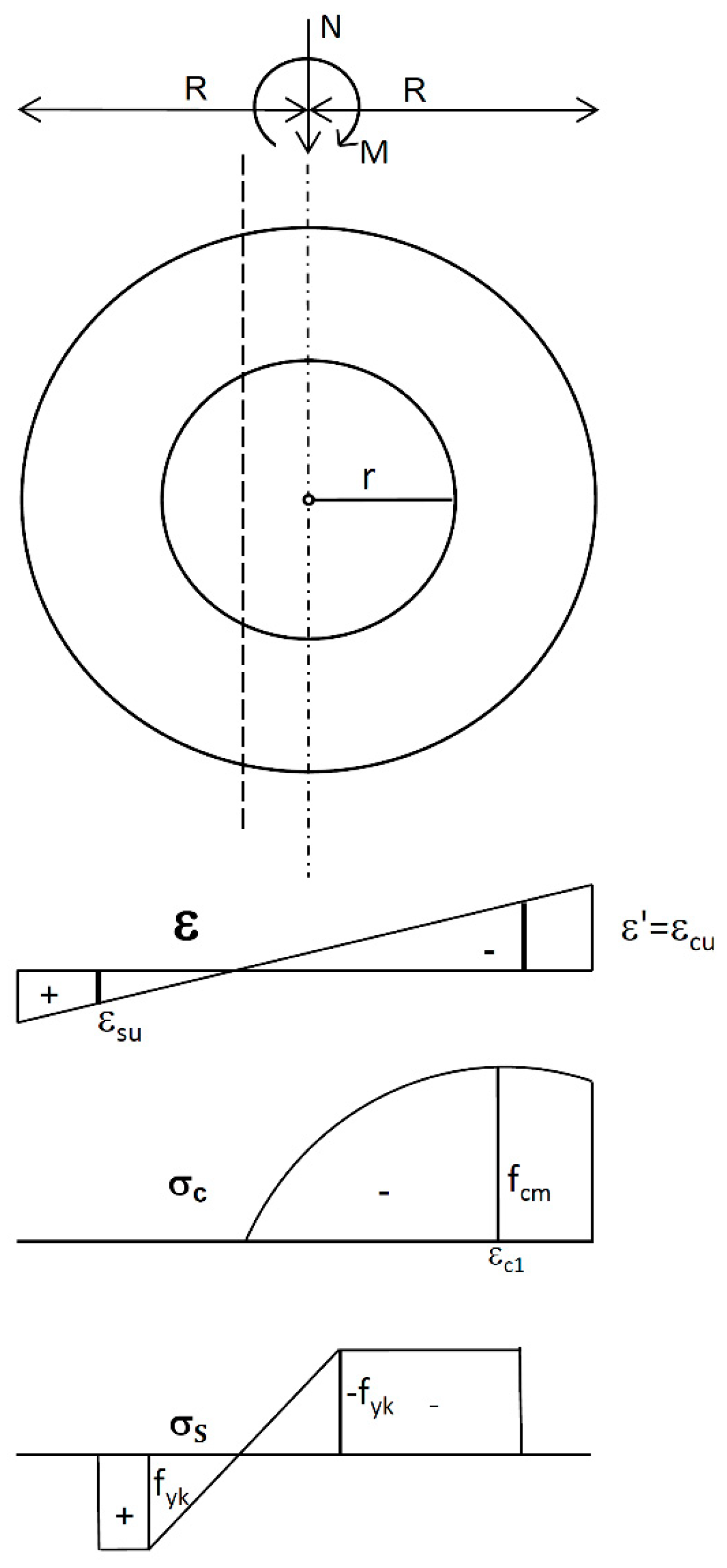
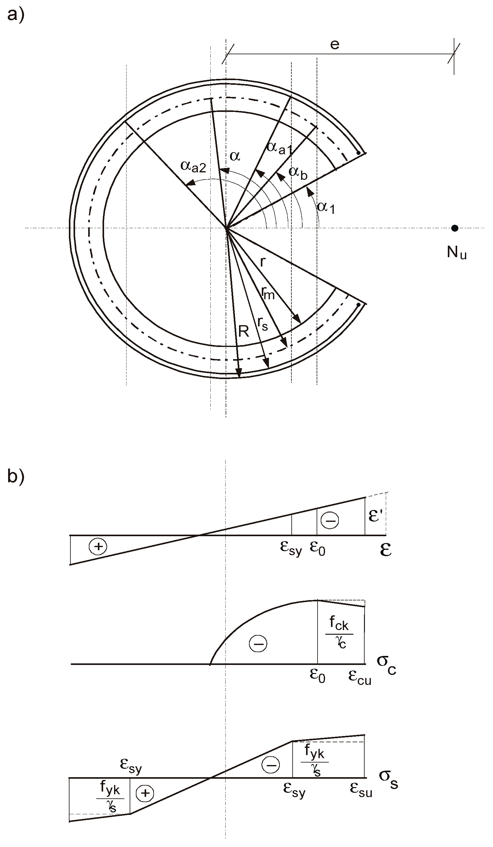
  • The RC ring cross-section of outer radius R, inner radius r and thickness t = Rr is subjected to axial force N and bending moment M (Figure 1). The section may be unreinforced or reinforced with the reinforcing steel spaced at one or two layers, which can be replaced by a continuous ring of equivalent area located on the reference circumference of radius rs, rrsR. When rs = R or rs = r, this reinforcement is treated as an “external reinforcement”.
  • For the section under combined compression and bending, the relations for strains in concrete εc (‰) and in reinforcing steel εs (‰) are given by the following.
ε c = ( cos ϕ cos α ) ε α ;
ε s = ( ρ cos ϕ cos α ) ε α .
All angles are measured from the compressive to the tensile zone. The sectional equilibrium equation of the axial forces is described as follows.
A c σ c d A c + A s σ s d A s + N = 0
The sectional equilibrium equation of the bending moments about the symmetry axis of the section is expressed as follows.
A c σ c r m cos ϕ d A c + A s σ s r s cos ϕ d A s M = 0
Taking into account physical and geometrical relationships (1)–(3) in equilibrium Equations (4) and (5), the problem results in a purely mathematical task consisting in searching the indefinite integrals of the following functions of variable ϕ:
f N ( ϕ ) = k k 2 ( cos ϕ k 1 ) k 2 2 ( cos ϕ k 1 ) 2 1 + ( k 2 ) k 2 ( cos ϕ k 1 ) ;
f M ( ϕ ) = k k 2 ( cos ϕ k 1 ) k 2 2 ( cos ϕ k 1 ) 2 1 + ( k 2 ) k 2 ( cos ϕ k 1 ) cos ϕ ,
where the following is the case.
k 1 = cos α ;   k 2 = ε α / ε c 1 .
Upon transformation, Equations (6) and (7) result in the following:
f N ( ϕ ) = ( k 2 / ( k 2 ) ) [ sin ϕ ( k 1 + W 2 ) + 2 W 1 W 2 1 cos ϕ + b ) ] ;
f M ( ϕ ) = ( k 2 / ( k 2 ) ) [ 0.5 ( 0.5 sin 2 ϕ + ϕ ) + W 1 W 2 ϕ k 1 W 2 sin ϕ 2 W 1 W 2 b / ( b 2 1 ) 1 cos ϕ + b ] ,
where W1 = 1/(k − 2)k2; W2 = W1 + k/k2; and b = W1k1.
An indefinite integral of function 1/(cosϕ + b) occurring in Equations (9) and (10) has been found as follows.
d ϕ cos ϕ + b = 2 b 2 1 a r c t g ( b 1 ) t g 0.5 ϕ b 2 1   for   b 2 > 1 ;
d ϕ cos ϕ + b = 1 1 b 2 ln | ( 1 b ) t g 0.5 ϕ + 1 b 2 ( 1 b ) t g 0.5 ϕ 1 b 2 |   for   b 2 < 1 .
Having calculated the definite integrals of Equations (9)–(12), normalized ultimate resistances nRm and mRm are obtained in the following final form:
n R m = ( k 2 / ( k 2 ) ) { sin α ( k 1 + W 2 ) α + 2 W 1 W 2 / ( b 2 1 ) arctg ( ( b 1 ) tg ( 0.5 α ) b 2 1 ) } + + μ f y k f c m { α 1 + ε α ε s s ( sin α 2 sin α 1 cos α ( α 2 α 1 ) ) [ π α 2 + ε s s ( π α 2 ) ] }
m R m = ( k 2 / ( k 2 ) ) { 0.5 ( 0.5 sin 2 α + α ) + W 1 W 2 α k 1 W 2 sin α 2 W 1 W 2 b / ( b 2 1 ) arctg ( ( b 1 ) tg ( 0.5 α ) b 2 1 ) } + μ f y k f c m { [ sin α 1 + ε s s sin α 1 ) ] + ε α ε s s ( 0.5 ( α 2 α 1 ) + 0.5 ( sin 2 α 2 sin 2 α 1 cos α ( sin α 2 sin α 1 ) ) + [ sin α 2 + ε s s sin α 2 ) ] }
where the following is the case.
NRm = N/(π dm t fcm); mRm = M/(π dm2 t fcm),
Here, μ is the reinforcement ratio; and α1 and α2 are angles determining the depth of the plastified zones of steel in compression and in tension, respectively.
The graphic interpretations of Equations (13)–(15) are the interaction diagrams with normalized resistances nRm-mRm valid for the case, when both compressive and tensile strains occur in the analyzed section characterized by the following: the limiting value εcu = −3.5‰; the concrete grade C20/25 (fcm = 28 MPa); fyk = 500 MPa; Ecm = 30 GPa; substitute reinforcement ratio μ fyk/fcm = 0; 0.1; 0 ≤ εs ≤ 10‰ (Figure 2). These curves denoted by the solid line (EC2) are compared with those based on the parabola–rectangle diagram (the dashed line, parabola). It is apparent that the coordinates of curves denoted by EC2 are lower than for the parabola due to the effect of concrete softening.
In a similar manner, the corresponding formulae are obtained for the section that is entirely in compression. The relevant relationship for strains is given by the following.
ε = 0.5 ( ε 2 ε 1 ) ( 1 cos ϕ ) + ε 1 .
The formulae determining cross-sectional forces nRm and mRm are described in the following form:
n R m = ( k 2 / ( k 2 ) ) π { ( k 1 + W 2 ) + W 1 W 2 / ( b 2 1 ) } + ( μ f y k / f c m ) { α 1 + 1 / ε s s [ ( k 1 + k 2 ) ( α 2 α 1 ) + k 2 ( sin α 1 sin α 2 ) + π α 2 ] }
m R m = ( k 2 ( k 2 ) ) π { 0.5 + W 1 W 2 2 W 1 W 2 b / ( b 2 1 ) } + ( μ f y k / f c m ) { sin α 1 + 1 / ε s s [ ( k 1 + k 2 ) ( sin α 2 sin α 1 ) 0.5 ( α 2 α 1 + sin 2 α 2 sin 2 α 1 ) sin α 2 ] }
where k1 = 2ε1/(ε2ε1) + 1; and k2 = −0.5 (ε2ε1)/εc1 shall be substituted.
For the section that is entirely in compression, when |εcu | > |εc1 |, Equations (17) and (18) describe the ring cross-section at the stage of concrete instability (at failure). This means that Drucker’s stability postulates may not be satisfied [38,40]. Therefore, the obtained curves cannot be, in general, regarded as the carrying capacity curves. This is the case presented in [9]. Figure 3 presents interaction curves (EC2) resulting in the relation (1) versus those derived on the basis of the parabola–rectangle (parabola) extended to the ring cross-section that is entirely in compression (εc1 = −2.0 ‰; εcu = −3.5‰), with a limitation to the values mRm ≥ 0. All curves in Figure 2 and Figure 3 satisfy the condition of convexity according to Drucker’s postulate. In particular, for εcu = εc1 = −2‰, the stability condition by Drucker is satisfied for any values of εc and εs. Thus, the obtained curves based on Equations (13)–(15) and Equations (17) and (18) can be regarded as the actual carrying capacity curves accepted in design codes. It is worth highlighting that these interaction diagrams (EC2) are very close to those based on the parabola–rectangle (parabola) (Figure 4).
As the next section model, the ring cross-section weakened by one opening is considered and is subjected to ultimate axial force Nu and bending moment Mu = Nu ⋅ e (Figure 5). The stress distributions in concrete and reinforcing steel are described by design values fcd = fckc and fyd = fyks, while the size of opening is denoted by angle α1. Following the above outlined algorithm, normalized ultimate resistances nu and mu are derived for this section in the following form:
+ μ f y d f c d [ α 1 α a 1 + ε α ε s s ( sin α a 2 sin α a 1 cos α ( α a 2 α a 1 ) ) + π α a 2 ] ; n u = ( k 2 / ( k 2 ) ) { sin α sin α 1 ( k 1 + W 2 ) ( α α 1 ) + 2 W 1 W 2 / ( b 2 1 ) [ arctg ( ( b 1 ) tg ( 0.5 α ) b 2 1 ) + - arctg ( ( b 1 ) tg ( 0.5 α 1 ) b 2 1 ) ] }
m u = ( k 2 / ( k 2 ) ) { 0.5 [ 0.5 ( sin 2 α sin 2 α 1 ) + α α 1 ] + W 1 W 2 ( α α 1 ) k 1 W 2 ( sin α sin α 1 ) + 2 W 1 W 2 b / ( b 2 1 ) [ arctg ( ( b 1 ) tg ( 0.5 α ) b 2 1 ) arctg ( ( b 1 ) tg ( 0.5 α 1 ) b 2 1 ) ] } + μ f y d f c d [ sin α 1 sin α a 1 + ε α ε s s ( 0.5 ( α a 2 α a 1 ) + 0.5 ( sin 2 α a 2 sin 2 α a 1 cos α ( sin α a 2 sin α a 1 ) ) sin α a 2 ]
where αa1 and αa2 are the angles determining the depth of the plastified zones of steel in compression and in tension, respectively.
The section model is frequently used in the structural design, e.g., flue opening in chimneys, windows in tower walls [8]. In a similar manner, the corresponding interaction diagrams can be constructed for other section shapes.

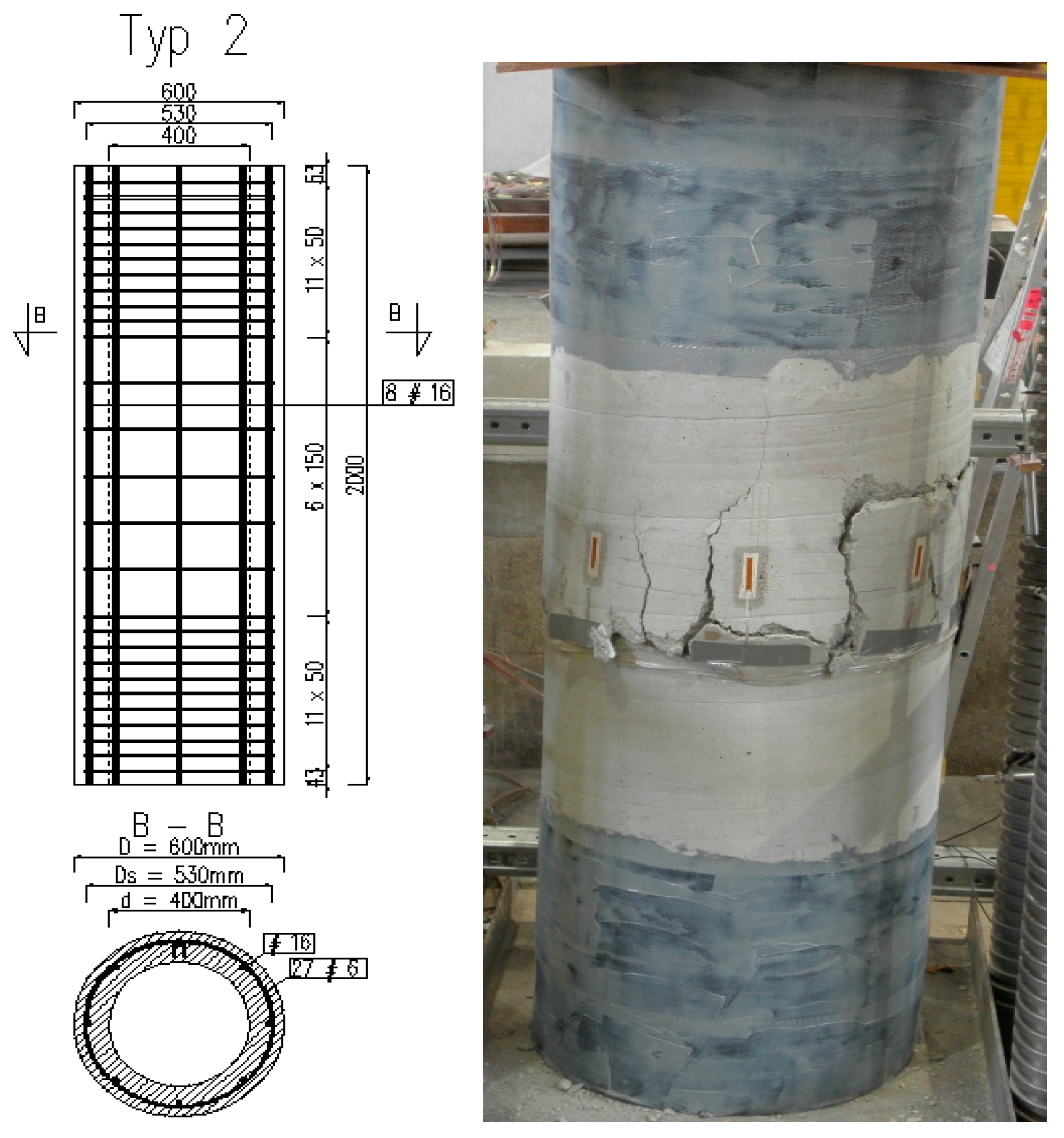
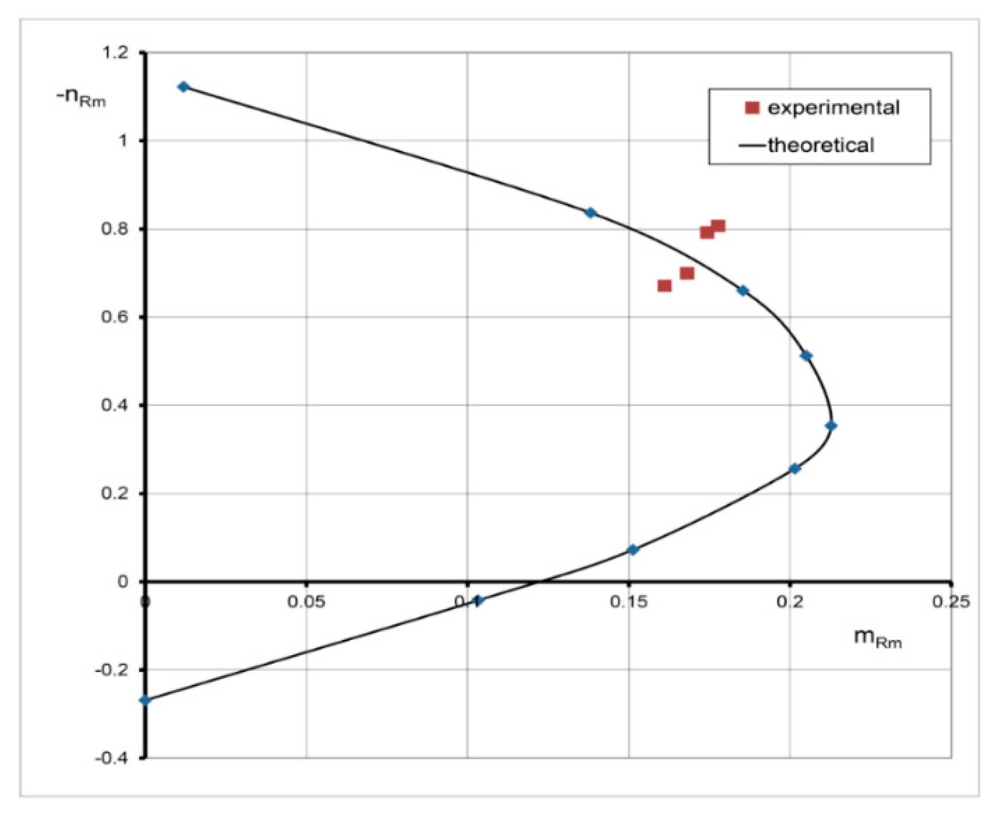
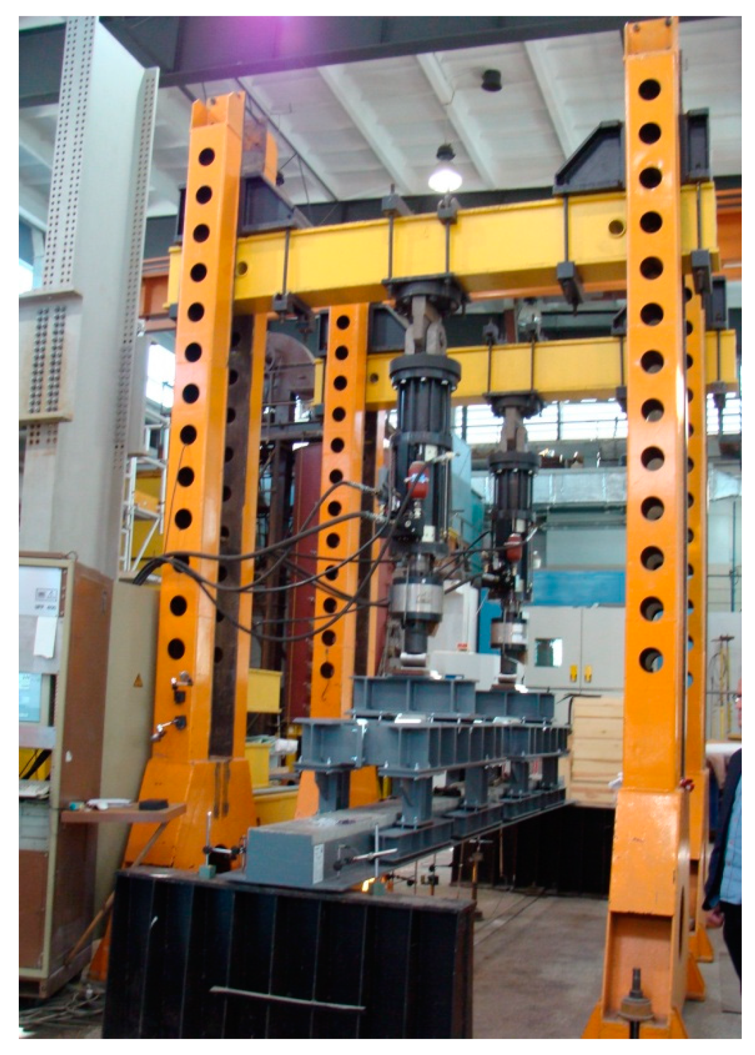
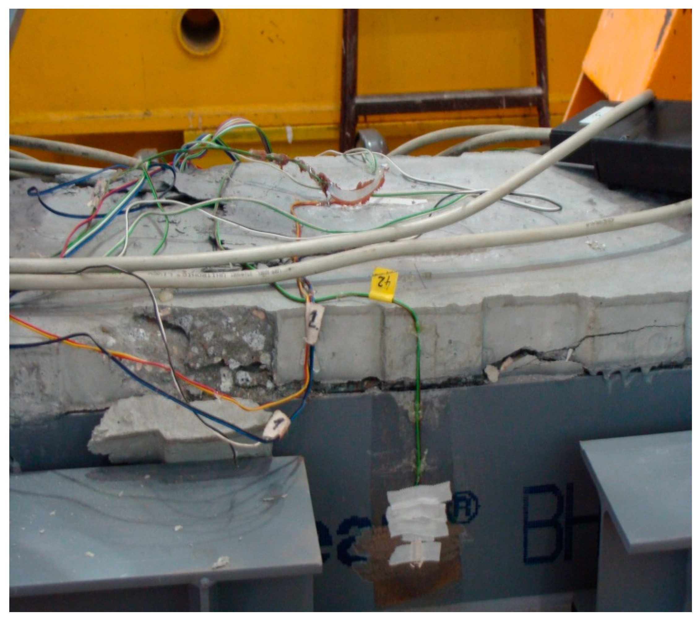
2.2. Experimental Verification with Discussion of the Results

Full-scale tests were carried out on four RC designed columns eccentrically loaded, with annular cross-section, denoted by Typ 2 [15]. The outer radius of all columns was R = 0.3 m, the inner one was r = 0.2 m and the height was h = 2.0 m. The mean compressive strength of the column concrete was determined as fcm = 20 MPa; Ecm = 27 GPa; and εc1 = −1.8‰ by strength test according to Polish Standard PN-EN 12390-3: 2011 [15]. The reinforcement of the columns consisted of longitudinal bars ∅16 mm made of steel B500C (fyk = 500 MPa) and its percentage was μ = 1.024%. The properties of the steel rebars were established in turn by tensile test according to Polish Standard PN-EN ISO 6892-1:2010, [15]. The columns were strengthened in the both support zones by CFRP mats at the length of 0.5 m. The tested specimens and the experimental setup are exhibited in Figure 6. In each load step, the strains were measured in the middle section using strain gauges located along its circumference up to failure. The test results of the examined columns are collected in Table 1. The failure of the columns manifested itself by crushing the concrete and yielding the longitudinal reinforcing steel for all tested members (Figure 6). The above-described test results have been compared with the cross-section model presented in Section 2.1. with the substitute reinforcement ratio of μ fyk/fcm = 0.2688. Using the derived Equations (13)–(18), the interaction chart nRm-mRm has been plotted. The effect of confinement of the column (stirrups) was not analyzed. The comparisons presented in Figure 7 illustrates a good convergence between the section model and the values of failure loads. The occurring differences between the analytical and the experimental results are caused by measurement uncertainty (strains, eccentricity) as well as by ignoring transverse reinforcement in the section model.

3. RC Rectangle Subjected to Bending without Axial Force

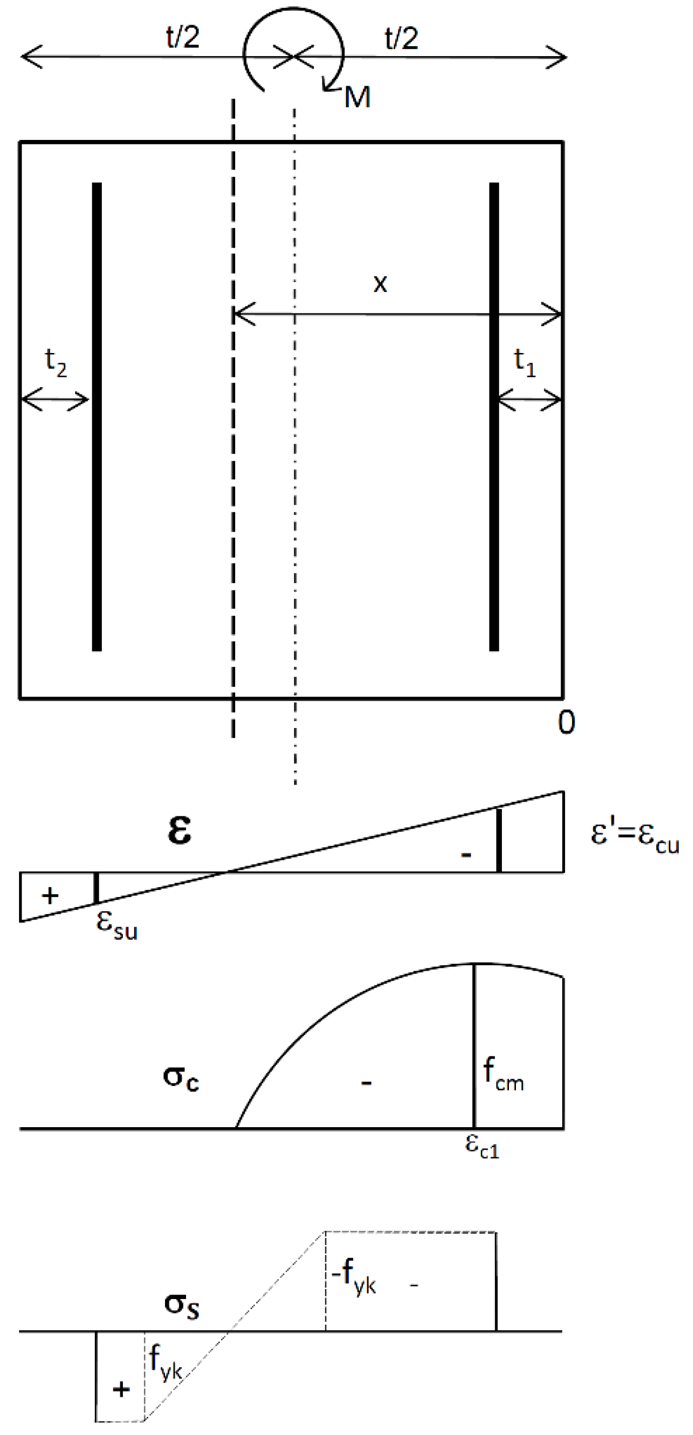
3.1. Derivation of the Ultimate Bending Moment

The RC rectangle of the height t and the width b is subjected to bending moment M without axial force (Figure 8).
The relation for strains can be expressed in the following form:
ε = ( 1 ξ ξ ) ε ,
where ξ′ = x’/t and ξ = x/t is the dimensionless coordinate of any point of the rectangle and the dimensionless coordinate describing the location of neutral axis.
The equilibrium equation of the bending moments about the horizontal axis of the RC rectangle is described as follows.
0 x σ c ( 0.5 t x ) d A c + σ s 1 F a 1 ( 0.5 t t 1 ) + σ s 2 F a 2 ( 0.5 t t 2 ) M = 0
As a result of integrating Equation (22), the normalized ultimate bending moment mRm is obtained in the following final form.
m R m = ( 1 / ( k 2 ) ) { 0.5 ( W 1 + ( 1 / ( k 2 ) ) ) ξ + 0.5 [ W 1 + 0.5 k 2 ( ( 1 / ( k 2 ) ) ] ξ 2 + ( 1 / 3 ) k 2 ξ 3 ( W 2 / ( ( k 2 ) W 3 ) ) [ 0.5 ln W + ξ ( W / W 3 ) ln W ] } + μ 1 f y k f c m ( 0.5 ξ 1 ) { δ k 1 + δ k 1 + 1 ε ε s s ( 1 ξ 1 ξ ) } + μ 2 f y k f c m ( 0.5 ξ 2 ) { δ k 2 + δ k 2 + 1 ε ε s s ( 1 1 ξ 2 ξ ) }
m R m = M R m b t 2 f c m
ξ = ( 1 ξ 1 ) ε c u 1 ε s u + ε c u 1 ;   ε = ε u c 1 ; ( 1 ξ 1 ) ε , = ε s u ;
k2 = ε′/(εc1 ξ); W1 = kk2ξ; W2 = k(k − 2) + 1; W3 = (k − 2)k2; W = 1 + (k − 2)k2ξ; δk = 0.5((−1)k + 1).

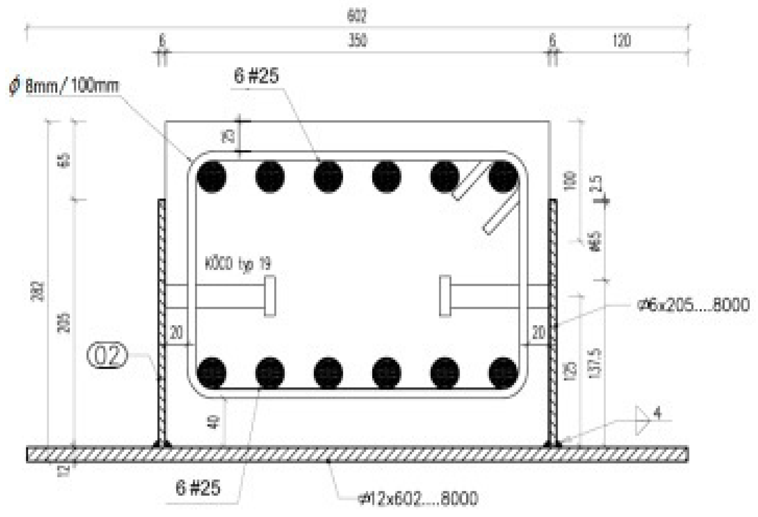
3.2. The Resistance of Composite Steel and Concrete Beams Versus Test Results

The presented section model can be applied for determining the resistance of composite steel and concrete beams, named BH beams, subjected to bending. The considered beams consist of a reinforced (RC) rectangular core placed inside a reversed TT-welded profile, as shown in Figure 9.
Ultimate bending moment MHRm determining the resistance of the considered BH beam is derived in terms of strains upon integrating the equilibrium equation of the bending moments about the horizontal axis of the RC core rectangle [28]. In this derivation, the reversed TT-welded profile is treated as the external reinforcement with respect to the RC rectangular core. To compare the obtained analytical solution with experimental results, four-point bending tests were conducted on three separated BH beams with the length of L = 7.88 m. They were made of concrete with a mean compressive strength of fcm = 68 MPa, which was determined by a strength test according to Polish Standard PN-EN 12390-3:2011 (concrete grade C 60/75; Ecm = 39 GPa). For the RC rectangle with the cross-section of 0.27 m × 0.35 m, the reinforcing steel with fyk = 500 MPa and the profile steel with fHyk = 460 MPa were used. The properties of the steels were established in turn by tensile tests according to Polish Standard PN-EN ISO 6892-1:2010. The setup of the tests is exhibited in Figure 10. The range of the tests included determining failure loads and the relevant strains. In each load step, the strains in concrete εc, in reinforcing steels in compression εs1 and in tension εs2, as well as in the lower flange of profile steel εHf, were measured in the middle section of the BH beam.
The failures of all BH beams manifested themselves by concrete crushing (Figure 11). Table 2 summarizes the values of strains, failure bending moments Mu and resistances MHRm. The compressive strains in concrete reached ultimate values. The value of εs1 = −2.89‰ indicates that the plastic strains in the rebars in compression may have occurred. The values of MHRm have been calculated in accordance with derived Equations (23)–(26). It is worth noting that they are close to failure bending moments Mu (relative differences 4.8–6.5%). This confirms very good agreements between resistances MHRm and the test results in ultimate bending moments Mu.

4. Conclusions

The complete analytical solution has been found for the resistance of RC ring cross-sections subjected to bending with axial force, based on the nonlinear material law for concrete and taking into account the effect of concrete softening. It applies both to designed and existing members and structures. In this respect, it can be regarded as a valuable one in the theory of reinforced concrete:
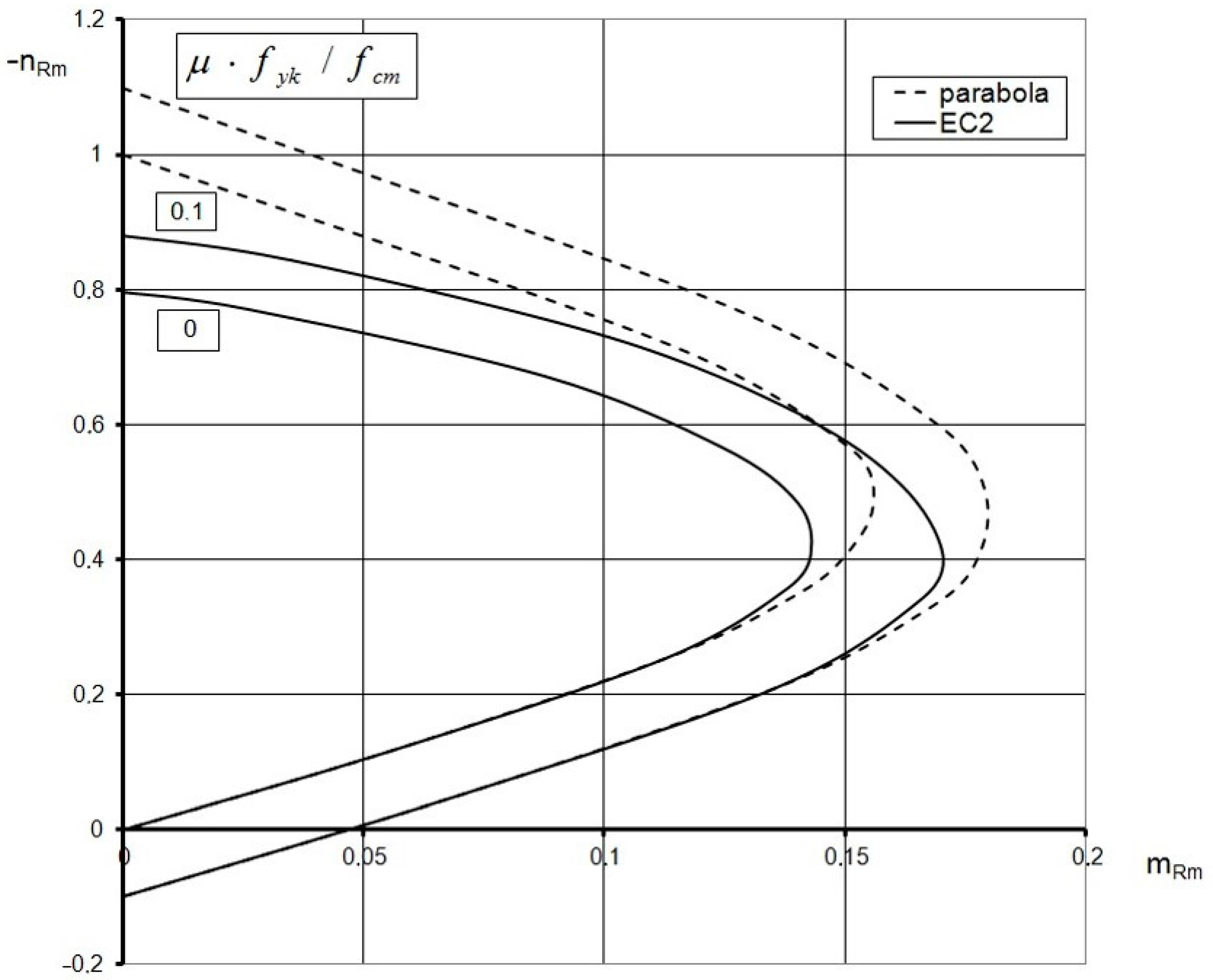
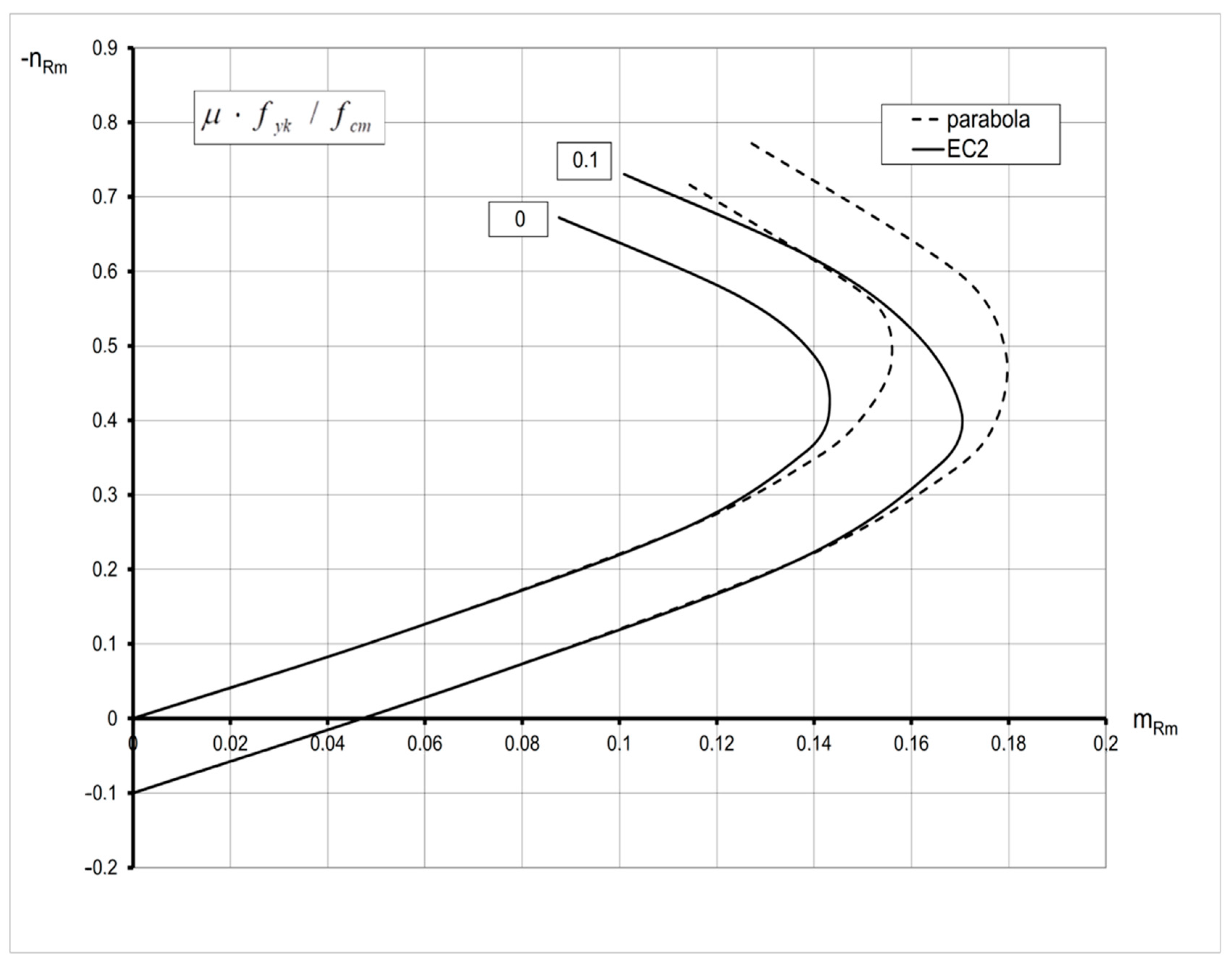
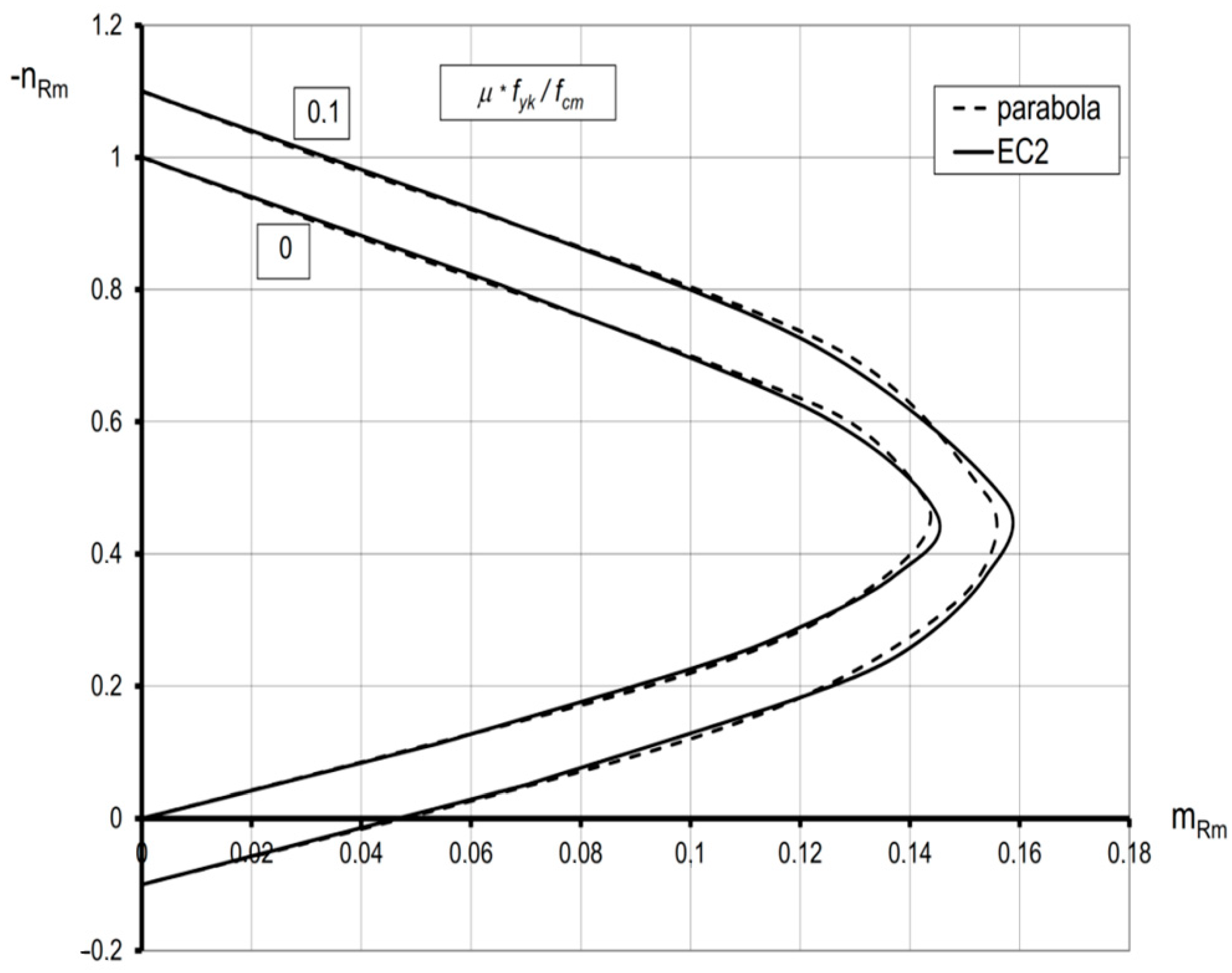
  • The obtained solutions are presented in the form of interaction diagrams that satisfy the conditions of convexity in accordance with Drucker’s postulates. This means that they can be regarded as the actual carrying capacity curves.
  • The proposed ring section models seem to have a wider application field than the previous ones, due to the assumptions of a noncentral layout of reinforcement and wall-edge strains. As a result, they are suitable for ring cross-sections with both the thin and moderate thicknesses. Furthermore, they can be easily adopted when structure strengthening is required by means of externally bonded CFRP, FRP or GFRP composites as well as for determining the resistance of composite steel and concrete columns.
  • Using this approach, the similar formulae can be derived for other sections commonly encountered in the engineering practice, for example, a rectangle and the ones weakened by openings.
  • It was proved that the computational results conform to those obtained by testing on RC eccentrically loaded columns.
  • The analytical solution was developed for the resistance of RC rectangle subjected to bending without axial forces to determine ultimate bending moment MHRm of the composite steel and concrete beams.
  • The comparisons made between the computational and test results of BH beams showed good agreements in ultimate bending moments.
  • The above-developed models enabled the analysis of the behavior of RC members in the postcritical phase.
  • They have been implemented in Excel to provide a useful tool for the dimensioning optimization of RC-designed members and structures that may result in a reduction in material consumption and a lesser impact on the environment.
  • Further experimental work is needed concerning the postcritical behavior of RC members.

Funding

This research received no external funding.

Institutional Review Board Statement

Not applicable.

Informed Consent Statement

Not applicable.

Data Availability Statement

Not applicable.

Conflicts of Interest

The author declares no conflict of interest.

Nomenclature

fcd = fckcdesign strength of concrete in compression
fckcharacteristic strength of concrete in compression
γcpartial safety factor for concrete
fcmmean compressive strength of concrete
fykyield stress of reinforcing steel
fyd = fyksdesign yield stress of reinforcing steel
γspartial safety factor for steel
fHykyield stress of profile steel
Ecmsecant modulus of elasticity of concrete
Esmodulus of elasticity of steel (profile steel)
εc1strain at peak stress on the σc-εc diagram
εcu1, εcuultimate strain for concrete
ε1, ε2maximum and minimum compressive strains, respectively
εsuultimate strain for reinforcing steel
εHfstrain in the lower flange of profile steel
eeccentricity
σc, εcstress, strain in concrete
σs, εsstress, strain in reinforcing steel
Naxial force
Mbending moment
Nu, Muultimate axial force and ultimate bending moment, respectively
nRm, nunormalized ultimate axial force
mRm, munormalized ultimate bending moment
b, tdimensions of the rectangular cross-section
t1, t2coordinates describing the locations of rebars
xcoordinate describing the location of the neutral axis
σs1compressive stress of steel
σs2tensile stress of steel
μ1, μ2reinforcement ratios of steels in compression and in tension (rectangle)
μreinforcement ratio (ring)
Router radius
rinner radius
t = Rrthickness of ring
rmmean radius
rsradius describing the locations of reinforcing steel on the reference circumference
dmmean diameter
αangle describing the location of the neutral axis, rad
ρ coefficient ρ = rs/rm
ρR coefficientρR = R/rm
ε maximum compressive strain in concrete, ‰
ε α = ε / ( ρ R cos α ) ;
ϕangular coordinate, rad
dAs, dAcelement of the steel area As and of the concrete area Ac, respectively
Fa1, Fa2areas of reinforcing steels in compression and in tension, respectively

References

  1. Knauff, M. Calculations of Reinforced Concrete Structures According to EC 2, 1st ed.; Scientific Publisher PWN: Warsaw, Poland, 2013. (In Polish) [Google Scholar]
  2. Nieser, H.; Engel, V. Structure of Industrial Chimneys, Commentary on DIN 1056, 1st ed.; Beuth Verlag GmbH: Berlin, Germany, 1986. [Google Scholar]
  3. International Committee on Industrial Chimneys. Model Code for Concrete Chimneys, Part A: The Shell, 2nd ed.; International Committee on Industrial Chimneys: Moers, Germany, 2011. [Google Scholar]
  4. Hognestad, E. Study of Combined Bending and Axial Load in Reinforced Concrete Members; Bulletin No. 399; University of Illinois Urbana: Champaign, IL, USA, 1951; p. 128. [Google Scholar]
  5. ACI 307–08; Code Requirements for Reinforced Concrete Chimneys and Commentary. American Concrete Institute: Farmington Hills, MI, USA, 2008.
  6. Popovics, S. A review of stress-strain relationships for concrete. ACI J. 1970, 67, 243–248. [Google Scholar]
  7. Popovics, S. A numerical approach to the complete stress-strain curve of concrete. Cem. Concr. Res. 1973, 3, 583–599. [Google Scholar] [CrossRef]
  8. Lechman, M. Resistance of RC annular cross-sections with openings subjected to axial force and bending. Eng. Trans. 2008, 56, 43–64. [Google Scholar]
  9. Lechman, M. Resistance of reinforced concrete columns subjected to axial force and bending. Transp. Res. Procedia 2016, 14, 2411–2420. [Google Scholar] [CrossRef] [Green Version]
  10. Lechman, M. A close to reality method for determining the resistance of RC structures under eccentric compression. Procedia Eng. 2017, 193, 58–65. [Google Scholar] [CrossRef]
  11. Majewski, T.; Bobiński, J.; Tejchman, J. FE analysis of failure behavior of reinforced concrete columns under eccentric compression. Eng. Struct. 2008, 30, 300–317. [Google Scholar] [CrossRef]
  12. Rodrigues, E.A.; Manzoli, O.L.; Bitencourt, L.A.G., Jr.; dos Prazeres, P.G.C.; Bitencourt, T.N. Failure behavior modeling of slender reinforced concrete columns subjected to eccentric load. Lat. Am. J. Solids Struct. 2015, 12, 520–541. [Google Scholar] [CrossRef] [Green Version]
  13. Kim, J.K.; Lee, S.-S. The behavior of reinforced concrete columns subjected to axial force and biaxial bending. Eng. Struct. 2000, 23, 1518–1528. [Google Scholar] [CrossRef]
  14. Lloyd, N.A.; Rangan, B.V. Studies on high-strength concrete columns under eccentric compression. ACI Struct. J. 1996, 93, 631–638. [Google Scholar]
  15. Chruściel, W. An Advanced Method for Calculating the RC Ring Cross-Section under Eccentric Compression. Ph.D. Thesis, Building Research Institute, Warsaw, Poland, 2013. [Google Scholar]
  16. Trapko, T.; Musiał, M. The effectiveness of CFRP materials strengthening of eccentrically compressed reinforced concrete columns. Arch. Civ. Mech. Eng. 2011, 11, 249–262. [Google Scholar] [CrossRef]
  17. Campione, G.; Fosetti, M.; Papia, M. Behavior of fiber-reinforced concrete columns under axially and eccentrically compressive loads. ACI Struct. J. 2010, 107, 272–281. [Google Scholar]
  18. El Maaddawy, T.; El Sayed, M.; Abdel-Magid, B. The effect of cross-sectional shape and loading condition on performance of reinforced members confined with carbon fiber-reinforced polymers. Mater. Des. 2010, 31, 2330–2341. [Google Scholar] [CrossRef]
  19. Elwan, S.; Rashed, A. Experimental behavior of eccentrically loaded RC short columns strengthened using GFRP wrapping. Struct. Eng. Mech. 2011, 39, 207–221. [Google Scholar] [CrossRef]
  20. Sadeghian, P.; Rahai, A.; Ehsani, M. Experimental study of rectangular RC columns strengthened with CFRP composites under eccentric loading. J. Compos. Constr. 2010, 14, 443–450. [Google Scholar] [CrossRef]
  21. Eid, R.; Paultre, P. Compressive behavior of FRP-confined reinforced concrete columns. Eng. Struct. 2017, 132, 518–530. [Google Scholar] [CrossRef]
  22. Wu, Y.; Jiang, C. Effect of load eccentricity on the stress-strain relationship of FRP-confined concrete columns. Compos. Struct. 2013, 98, 228–241. [Google Scholar] [CrossRef]
  23. Quiertant, M.; Clement, J. Behavior of RC columns strengthened with different CFRP systems under eccentric loading. Constr. Build. Mater. 2011, 25, 452–460. [Google Scholar] [CrossRef]
  24. Evirgen, B.; Tuncan, A.; Taskin, K. Structural behavior of concrete filled steel tubular sections (CFT/CFST) under axial compression. Thin-Walled Struct. 2014, 80, 46–56. [Google Scholar] [CrossRef]
  25. Han, L.-H.; Li, W.; Bjorhovde, R. Developments and advanced applications of concrete –filled steel tubular (CFST) structures: Members. J. Constr. Steel Res. 2014, 100, 211–228. [Google Scholar] [CrossRef]
  26. Huang, H.; Han, L.-H.; Tao, Z.; Zhao, X.-L. Analytical behavior of concrete-filled double skin steel tubular (CFDST) stub columns. J. Constr. Steel Res. 2010, 66, 542–555. [Google Scholar] [CrossRef]
  27. Qu, X.; Chen, Z.; Sun, G. Experimental study of rectangular CFST columns subjected to eccentric loading. Thin-Walled Struct. 2013, 64, 83–93. [Google Scholar] [CrossRef]
  28. Lechman, M.; Stachurski, A. Determination of stresses in RC eccentrically compressed members using optimization methods. AIP Conf. Proc. 2018, 1992, 130003. [Google Scholar]
  29. Lewiński, P.M.; Więch, P.P. Analytical model and numerical research of composite beams with horizontal studs. In Proceedings of the 8th International Conference “Analytical Models and New Concepts in Concrete and Masonry Structures”, Wrocław, Poland, 16–18 June 2014. [Google Scholar]
  30. Lewiński, P.M.; Derysz, J.; Dudziak, S.; Więch, P.P. Newly designed structural solutions for the “Slim floor” composite system. In Proceedings of the Fib Symposium 2019—Concrete: Innovations in Materials, Design and Structures, Krakow, Poland, 27–29 May 2019. [Google Scholar]
  31. Lechman, M. Analytical solution for the resistance of composite beams subjected to bending. MATEC Web Conf. 2020, 323, 01013. [Google Scholar] [CrossRef]
  32. EN 1994-1-1:2004; Eurocode 4: Design of Composite Steel and Concrete Structures—Part 1-1: General rules and rules for buildings. European Union: Brussels, Belgium, 2005.
  33. Elnashai, A.S.; Papazoglou, A.J. Procedure and spectra for analysis of RC structures subjected to strong vertical earthquake loads. J. Earthq. Eng. 1997, 1, 121–155. [Google Scholar] [CrossRef]
  34. Parisi, F.; Augenti, N. Influence of seismic design criteria on blast resistance of RC framed buildings: A case study. Eng. Struct. 2012, 44, 78–93. [Google Scholar] [CrossRef]
  35. Noble, D.; Nogal, M.; O’Connor, A.; Pakrashi, V. The effect of prestress force magnitude and eccentricity on the natural bending frequencies of uncracked prestressed concrete beams. J. Sound Vib. 2016, 365, 22–44. [Google Scholar] [CrossRef] [Green Version]
  36. Bonopera, M.; Chang, K.-C.; Chen, C.-C.; Sung, Y.-C.; Tullini, N. Prestress force effect on fundamental frequency and deflection shape of PCI beams. Struct. Eng. Mech. 2018, 67, 255–265. [Google Scholar]
  37. Vlase, S.; Marin, M.; Deaconu, O. Vibration properties of a concrete structure with symmetries used in civil engineering. Symmetry 2021, 13, 656. [Google Scholar] [CrossRef]
  38. Drucker, D.C. A definition of a stable inelastic material. ASME J. Appl. Mech. 1959, 26, 101–195. [Google Scholar] [CrossRef]
  39. EN 1992-1-1: 2010; Eurocode 2: Design of Concrete Structures—Part 1-1: General rules and rules for buildings. European Union: Brussels, Belgium, 2004.
  40. Hill, R. General theory of uniqueness and stability in elastic-plastic solids. J. Mech. Phys. Solids 1958, 6, 236–249. [Google Scholar] [CrossRef]
Figure 1. Representation of the RC ring cross-section; distribution of strains ε; stresses in concrete σc; and stresses in reinforcement σs.
Materials 15 01957 g001
Figure 2. Interaction curves nRm-mRm based on nonlinear relation σc-εc (EC2) versus those based on the parabola–rectangle material law (parabola) for the ring section subjected to bending with axial compressive force (εcu = −3.5‰).
Materials 15 01957 g002
Figure 3. Interaction curves nRm-mRm based on nonlinear relation σc-εc (EC2) versus those based on the parabola–rectangle material law for concrete (parabola), extended for the ring cross-section that is entirely in compression (εcu = −3.5‰; mRm ≥ 0).
Materials 15 01957 g003
Figure 4. Comparison of the solution based on nonlinear relation σc-εc (EC2) with that based on the parabola–rectangle material law for the ring cross-section (parabola) and the limiting value εcu = εc1 = −2‰.
Materials 15 01957 g004
Figure 5. (a) Representation of the RC ring cross-section weakened by one opening; (b) distribution of strains ε, stresses in concrete σc and stresses in reinforcing steel σs.
Materials 15 01957 g005
Figure 6. The specimen and the failure mode of the column under eccentric loading.
Materials 15 01957 g006
Figure 7. Comparison of theoretical and experimental data.
Materials 15 01957 g007
Figure 8. The RC rectangle; distribution of strain ε, stresses in concrete σc and stresses in steel σs.
Materials 15 01957 g008
Figure 9. The cross-section of the composite beam under consideration.
Materials 15 01957 g009
Figure 10. Setup of the bending tests.
Materials 15 01957 g010
Figure 11. The characteristic failure mode of the BH beams.
Materials 15 01957 g011
Table 1. Test results of the eccentrically loaded columns.
Load Eccentricity
(cm)
Failure Load
(kN)
Ultimate Compressive Strain
in Concrete
(‰)
1124902.6
1221102.5
1222002.5
1125353.4
The mean value εcu = 2.8‰.
Table 2. Bending test results of the BH beams.
ConcreteReinforcement
in Compression
Reinforcement
in Tension
Profile SteelFailure
Moment
Resistance
strain εc
(‰)
strain εs1
(‰)
strain εs2
(‰)
strain εHf
(‰)
Mu
(kNm)
MHRm
(kNm)
−3.21−2.891.152.22902.8847.7
−3.04−2.131.132.25883842.4
−2.90−2.01.252.28910.7854.8
Publisher’s Note: MDPI stays neutral with regard to jurisdictional claims in published maps and institutional affiliations.

