Article

Multi-Parameter Characteristics of Electric Arc Furnace Melting

1
COGNOR SA Branch HSJ in Stalowa Wola, Kwiatkowskiego 1, 37-450 Stalowa Wola, Poland
2
Department of Ferrous Metallurgy, Faculty of Metals Engineering and Industrial Computer Science, AGH-University of Science and Technology, 30 A. Mickiewicza A., 30-059 Krakow, Poland
*
Author to whom correspondence should be addressed.
Materials 2022, 15(4), 1601; https://doi.org/10.3390/ma15041601
Submission received: 31 January 2022 / Revised: 12 February 2022 / Accepted: 17 February 2022 / Published: 21 February 2022
(This article belongs to the Special Issue Metallurgical Process Simulation and Optimization)

Abstract

:
The article presents the results of analyses of numerical modelling of selected factors in electric arc furnace melts. The aim of the study was to optimise the melting process in an electric arc furnace using statistical-thermodynamic modelling based on, among other things, multiple linear regression (MLR). The article presents tools and methods which make it possible to identify the most significant indicators of the process carried out on the analysed unit from the point of view of improvement. The article presents the characteristics of the process and creation of the MLR model and, by applying its numerical analyses and results of calculations and simulations for selected variables and indicator, identifying the operation of a selected furnace. Developed model to demand of electric energy identification was used for calculations of energy balances, the distribution of the energy used in the furnace was presented.

1. Introduction

Observed climatic changes in the environment are causing recycling technologies for steel production to increase their share in the total balance of crude steel production. This is particularly noticeable in the European Union. Therefore, the electric arc furnace is becoming one of the leading processing units for steel scrap used in crude steel production [1]. Electricity consumption in this process still accounts for about 50–80% of the total energy consumption during melting. Technological progress and the development of information technology create opportunities to reduce the unit demand for electrical or chemical energy.
Mathematical descriptions and characterisations of the arc furnace smelting process are complicated due to its nature resulting from, among others, high temperature and chemical composition gradients, turbulent flows, multiphase and heterogeneity of the system, significant mass flow of substrates, high speed of phase transformations and non-linearity of phenomena. Therefore, the development of modelling of selected stages or the entire arc furnace smelting process remains justified [2].
The models used to describe the melting technology can be physical models—reproducing the processes on a smaller scale (e.g., laboratory and/or using other media than liquid metal and slag with the use of criterion numbers). An example of the application of a high-temperature model can be the studies on the performance of burners in an electric arc furnace carried out by Yonmo Sung [3]. They presented modification of oxy–gas burners, which was validated on a test bench.
Studies of scrap melting phenomena were also carried out based on water models [4] (using ice, three heating rods, and steam nozzles, which reflected scrap, electric arc, and oxy–gas burners, respectively).
Numerical methods can also be used to model the process. Mombeni [5] used a CFD model calculated in the commercial software ANSYS FLUENT to address the crack formation of water-cooled panels installed in the furnace vault. CFD modelling can also be used to determine the temperature distribution in a metal bath in the context of burner placement and media flow rates [6].
However, the mathematical models are the most universal method, which take into account physicochemical processes, thermodynamic and theoretical equations, mass and energy balances, or only technological data from the process [7]. They can be divided into two categories: linear and non-linear.
Linear models are created as a linear combination of predictor variables [8] based on average statistical input and output data from the process, or assumed theoretical values. They describe the relationship between individual parameters and their importance for the outcome of the calculation. Linear models are static and refer to only two points in time; they are the result of input data and, as mentioned above, they can only be used with reference to average values of a given process [9].
The most popular is the Kohle model, which describes the influence of process parameters on electricity demand.
Another model based on a multivariate linear regression equation is the one developed by Haupt [10]. He determined the influence of scrap quality on the melting process in an electric arc furnace.
However, non-linear models have the ability to describe the process more accurately. R. Morales created one of the first models, which included heat and mass transfer calculations and chemical reaction kinetics in terms of use the direct reduced iron [11]. The author created a dynamic model, which took into account the relationships between individual phenomena in terms of their physical course and not just the result, which was a statistical outcome of many variables. Thus, it makes it possible to analyse single melts and to follow the course of change of the result in time.
Attempts have been made to simplify the models and organise their construction. Clear boundaries of individual zones in the furnace were set. In terms of both: furnace construction, melting stages, and division into individual phases of materials/substances present in the furnace space. Bekker [12] specified two groups of solids and liquids in the constructed model. On the other hand, Logar [13,14] created a system of dependent modules representing particular groups of phenomena (including solid scrap zone, solid slag zone, liquid slag zone, liquid metal zone, and wall and roof zone). Models using neural networks are becoming increasingly popular. The first versions were developed in the 1990s. Ledoux and Bonnard, in their work, built a model based on a multi-layer perceptron. The model described the dynamics of an electric arc during the melting process.
Due to the process complexity, it is necessary to select models in such way that sufficient representation of the processes is maintained with the best possible ability to interpret and understand the simulation results [15]. The balance between these two characteristics depends largely on the type of models and the modelling methods [16].

2. Materials and Methods

2.1. Theoretical Mathematical Models

Mathematical models are the most commonly used in EAF simulation. They can be both linear and non-linear in nature. This classification results from taking into account the above-described variability of process efficiency as well as the variability of the parameters themselves during the melt [17]. Taking into account the kinetics of the reaction or the variation in the efficiency of media use or their control transforms the model into a non-linear form. Non-linearity is understood as effects ranging from media consumption dependent on melting programmes to the dependence of heat losses on the number and height of scrap heaps and thus arc exposure. When creating mathematical models, theoretical data or available technological and statistical data are used—which, depends on their availability and quality.

2.2. Linear Modelling of Steel Melting in Electric Arc Furnace

Regression linear models are created as a linear combination of predictor variables based on statistical mean input and output data from a process, or assumed theoretical values. This means that they refer to (only) two points in time, they are the result of input data and, e.g., output data, and as mentioned above, and they can only be used with respect to the average values of a given process. Static models often do not take into account some process disturbances and micro-scale phenomena (of low weights) and, therefore, their use for the analysis of single melts becomes difficult or, even impossible, due to the high variability of the real process conditions [18].
The most widely used statistical model in the literature is the Köhle model [18,19]. Köhle’s Equation (1) describing the demand for electricity:
W r kWh / t = 300 + 900 [ G E G A 1 ] + 1600 G Z G A + 0.7 [ T A ° C 1600 ] + 0.85 t S + t N min 8 M G m 3 / t 4.3 M L m 3 / t
where Wr is the electric energy demand, kWh/Mg; GE is the weight of ferrous materials, kg; GA is the tap weight (mass of the bath), kg; GZ is the weight of slag components, kg; TA is the temperature before taping, °C; tS is the power on time, min; tN is the power off time, min; MG is the natural gas consumption, Nm3; and ML is the oxygen consumption, Nm3.
This model characterises the electric energy demand, which in this case (of the units analysed by Köhle) is between 380 and 600 kWh/Mg with an accuracy equal to the standard deviation of 5 kWh/Mg.
The disadvantage of this solution is the low sensitivity of the model to changes in process conditions (occurrence of disturbances, change of the melting programme for the arc control system, or burners) which translates into a high error for individual melts. However, it is also an advantage in terms of long-term prediction. The Köhle model, due to its hybrid empirical–theoretical character, remains easy to interpret while maintaining sufficient accuracy.
In industrial practice, problems are encountered due to, e.g., insufficient process metering and difficult definition of boundary conditions. The amount of electrical energy supplied is easy to determine, whereas the efficiency of heat transfer through the arc depends on a large number of factors, e.g., the melting stage, the phenomena associated with arc burning (arc length, arc stability), or the plasma temperature associated with the gas atmosphere of the furnace, as well as the parameters characterising the steel scrap. Identifying the efficiency of the use of chemical energy—dependent on the reactions taking place in the reactor, which is the volume of the furnace bowl—is also a challenge. Its determination requires the identification of the reactions taking place and the distribution of the heat obtained between the phases, as well as the dynamics of the process [11,12,13,20].
When constructing models, it is necessary to perform mass and energy balances. Carrying out correctly defined balance calculations (of mass and energy) is essential from the point of view of the overall characteristics of the energy efficiency of the process and the determination of process boundary conditions [11].
In the course of the analyses, a database of indicators and technological parameters was created, which included 1953 records from one specific EAF. Due to a wide range of steel grades, the database was based on the most frequently manufactured group of steel grades and data was selected by rejecting melts:
  • from furnace start-up periods;
  • with furnace operation disturbances;
  • switching from or to grades with large differences in chemical composition, when there was a justified suspicion of wet pouring;
  • with process parameter values that are outliers.
The parameters included in the database are batch, material, and energy parameters.

2.3. Mass Balances

The mass balance is based on the assumption that the sum of the masses of the inputs min equals the sum of the outputs mout.
m scr + m sf + m c + m fa + m ox + m CH 4 + m la = m hm + m sl + m f + m wg
where mscr is the mass of the scrap, kg; msf is the mass of the slag formers, kg; mox is the mass of the oxygen, kg; mCH4 is the mass of the natural gas, kg; mc is the mass of the carburizer, kg; mfa is the mass of the foaming agent, kg; mla is the mass of the leaked air, kg; mhm is the mass of the hot metal, kg; msl is the mass of the slag, kg; mwg is the mass of the waste gases, kg; and mf is the mass of the fumes, kg.
For the purposes of consideration, the assumption has been made that the mass of the hot heel does not change between heats. In reality, the mass of hot heel changes and is difficult to estimate due to the relatively small volume it occupies and the constant irregular changes in the scale changing the volume of the furnace hearth.

2.3.1. Slag Weight Calculations

Slag mass was calculated on the basis of the chemical composition of the scraps used, assuming that the elements contained in them: Si, Mn, Cr, C, P, and Al are oxidised to the average of the level characterising the composition of the metal bath, and the amount of oxidised Fe constitutes 5.5% of the charge mass. These elements and the oxygen needed to burn them together with the addition of CaO and MgO make up the slag mass. The slag mass also includes ash from carbon carriers.
Chemical compositions of the slags were identified via energy dispersive X-ray fluorescence (XRF Oxford X-MET 3000TX +). In order to identify the chemical composition of the steel, a spectrophotometric method of analysis was used on a FOUNDRY-MASTER spark spectrometer.
The correctness of assumptions and calculations was checked by calculating the slag mass on the basis of CaO introduced into the process, which, as a component not dissolving in the metal bath, theoretically remains entirely in the slag.
m sl = ( m CaO   met . · 0.958 + m CaO   inj . · 0.864 ) · 100 % % CaO slag
where mCaO met. is the mass of the metallurgical calcium, kg; mCaO inj. is the mass of the injected pulverized calcium, kg; and %CaOslag is the percentage of mass weight of CaO in slag.
A calculation was then made of the mass of each element that was oxidised during bath melting and slag formation, thus reducing the metal yield.
m ae = M A e · % tl   ·   m sl M A o .  
where mae is the mass of the alloying element melted in slag, kg; %tl is the percentage of mass weight of given element in slag; M A e is the atomic mass of element, u; and M A o is the atomic mass of oxide of given element, u.

2.3.2. Calculation of Waste Gas Masses

In order to calculate the mass of waste gases taking into account the course of the reaction of combustion of coal and methane, Reactions (5)–(7) were written:
C + 1 2 O 2 CO
C + O 2 CO 2
CH 4 + 2 O 2 CO 2 + 2 H 2 O
The mass of carbon monoxide and carbon dioxide for each reaction for one kilogram of product burnt was calculated. The values obtained were, respectively, 2.33 kg, 3.67 kg, and 2.75 kg (from Reactions (5)–(7)). Due to the lack of measurement of the flue gas composition, it was assumed that all the substrates burned completely, and left entirely with the flue gases. Therefore, in the mass of waste gasses mwg, the components according to the Equation (8) are included:
m wg = m N 2 + m CO 2 + m H 2 O

2.3.3. Calculation of Metal Bath Weight

The theoretical weight of the metal bath was calculated as the difference between the weight of the scrap, the alloying elements contained in the bath (including iron), and the estimated amounts of fumes.
m hm = m scr Σ m ae m f
where mhm is the mass of hot metal, kg; mscr is the mass of the scrap, kg; mae is the sum of masses of alloying elements that went into slag, kg; and mf is the mass of the fumes, kg.

2.4. Energy Balances

The energy balance assumes that the sum of the energy input Ein into the process is equal to the sum of the energy output from the process in the form of product heat Qout and thermal losses Qloss. The energy input to the system consists of electrical energy and chemical energy. In the other direction, the energy is transferred out of the process in the form of metal baths, liquid slag, waste gases, dusts, and heat losses.
E el . + E chem . = Q hm + Q sl + Q wg + Q f
where Eel. is the electrical energy, MJ; Echem. is the chemical energy, MJ; Qhm is the heat of hot metal, MJ; Qsl is the heat of the slag, MJ; Qwg is the heat of waste gases, MJ; and Qf is the heat of the fumes, MJ.
The chemical energy was calculated on the basis of enthalpies of exothermic reactions—oxidation of bath components and combustion of methane. The Perry Nist Janaf method was used to calculate the enthalpies of the reactions.

2.4.1. Calculation of the Physical Heat of Hot Metal

Calculation of the physical heat of the hot metal is based upon the values of the specific heat of the hot metal, its mass, and the temperature rise. It also takes into account the phase transition by using the values of latent heat, liquid temperature, and differentiation of specific heat into that occurring in the liquid and solid state.
For the calculation of the physical heat of the metal bath, the Formula (11) is used:
Q hm = m hm · ( c ss · ( T m T a ) + Q lst + c ls ( T T m ) ) / 1000
where, Qhm is the physical heat of the metal bath at temperature T, MJ; mhm is the mass of hot metal, kg; css is the average specific heat of steel in the solid state, kJ/kg K; cls is the average specific heat of steel in the liquid state, kJ/kg·K; Qlst is the latent heat of fusion of steel, kJ/kg; T is the steel tap temperature, K; Tm is the steel melting temperature, and K; Ta is the ambient temperature, K.
The specific heat of the liquid state was taken as 0.836 MJ/Mg·K and that of the solid state as 0.698 MJ/Mg·K. The latent heat of fusion for the steel was taken as 271.7 kJ/kg.
The melting point of steel with a hot metal composition was calculated according to the Formula (12):
T m = T Fe i = 1 n p i k i
where Tm is the melting point, K; TFe is the melting point of pure iron (1812 K); pi is the percentage content of the element in the metal bath, %; and ki is the temperature reduction factor (according to the Table 1) [21].

2.4.2. Calculation of the Physical Heat of Slag

The calculation of the physical heat of slag was based on the values of the slag’s specific heat, mass, temperature rise, and latent heat. The following Formula (15) was used to calculate the physical heat of slag:
Q sl = m sl ( c sl ( T T a ) + Q lsl ) 1000
where Qsl is the physical heat of slag at temperature T, MJ; msl is the slag mass, kg; csl is the specific heat of slag at temperature T, kJ/kg·K; Qlsl is the latent heat of melting of slag, kJ/kg; T is the slag tap temperature, K; and Ta is the ambient temperature, K.
The specific heat of slag was calculated from the Formula (14):
c sl = 0.736 + 2.93 · 10 4 T
The assumed latent heat of fusion is 209 kJ/kg.

2.4.3. Calculation of the Physical Heat of Waste Gases

The calculation of the physical heat of the waste gases is based on the specific heat values of the gases of their mass and temperature rise. The formula was used to calculate the physical heat of the waste gases:
Q wg = m wg c wg ( T T a ) / 1000
where Qwg is the physical heat of the waste gases at temperature T, MJ; mwg is the mass of the waste gases, kg; cwg is the specific heat of the waste gases at temperature T, kJ/kg·K; T is the temperature of the gases, K; and Ta is the ambient temperature, K.
The average specific heat of the waste gases is 1.33 kJ/Nm3, whereas 1450 °C was taken as the value of gas temperature.

3. Results

In the field of research, considering modelling (MLR) as a first step, an attempt was made to apply and subsequently modify the Köhle equation [22]. Based on the analyses carried out on a furnace operating under the industrial conditions, one should state the lack of universality for the form of the model proposed by Köhle. The obtained values differ from the measured ones by an average of 50% for the 1992 version and by an average of 10% for the 2002 version of the equation [23]. As part of the work performed, the model was modified, and one of the changes made was the replacement of the ML coefficient relating to oxygen consumption by an equation taking into account the heat gain from the oxidation of individual elements. This is due to the previously mentioned large number of scrap classes, as well as the large share of the iron oxidation reaction as a source of chemical energy. Therefore, the replacement of the coefficient that represents the average heat gain by a separate function is justified. This function is written in the form:
E M = M ( M sl · M AM · avg % MO . sl · 1000 kg Mg 100 % · M AMO · Δ H M )
where Msl is the mass of slag, Mg; MAM is the atomic weight of considered metal, u; avg%MO.sl is the average considered metal oxide content of slag, %; MAMO is the atomic weight of considered metal oxide, u; and ΔHM is the the enthalpy of the oxidation reaction of a considered element, converted to kWh/kg; (where M = Cr, Mn, Fe, Al, Si).
Figure 1 shows the comparison of the real values of electricity consumption with the model values obtained based on two versions of the Köhle model: the 2002 version and its modification. It can be noted that for the modified version a much higher model fit was obtained (average difference 1%, maximum 20%).
In the realities of the furnace characterised, the model did not adequately provide quantitative answers as to what steps and extent of change should be taken to optimise the process.
Therefore, mass and energy balances were calculated and a linear multiple regression (MLR) model was undertaken.
For the calculation of mass and energy balances, it was necessary to identify the chemical composition of the liquid products (slag and steel). For this purpose, slag and metal samples were taken. A study of the chemical composition of slags was carried out for 200 melts in the same group of steel grades. The obtained average chemical compositions of slag and steel are presented in Table 2 and Table 3.
In the case of the unit under consideration, the insufficient metering, the high diversification of the steel grades, and the high variability of the charge (based on more than 40 scrap grades) led to some simplifications. For example, assuming a constant hot heel level; ignoring the change in furnace geometry resulting from erosion of the lining and, thus, assuming that the oxygen stream always reaches the bath and is fully consumed; and assuming that the chemical composition of the scrap corresponds to the average of the ranges described in PN 85/H 15000.
The results of the mass and energy balances obtained, and their analysis, clearly indicate the areas which should be investigated in order to improve the scrap melting process, e.g., appropriate use of natural gas, problems with furnace leak-tightness, and use of oxygen. However, the predominance of chemical energy in the melting process suggests that its optimisation will have a significant impact on the overall energy balance of the melt.
The parameters used to create the MLR were time, which is related to the amount of heat loss in the process; oxygen and gas consumption, as sources of chemical energy; the amount of slag-forming materials used, whose melting requires a significant amount of energy; and the scrap yield, which gives information on the amount of iron oxidised.
Calculations and multiple regression analyses were carried out to obtain the equation identifying the demand for electric energy. Table 4 presents the results for the selected backward MLR analysis, which gave the selected statistical model—the form of Equation (17). Statistical calculations were performed for the total sample size, which was N = 1959; the significance level of α = 0.05 was assumed. Statistical correlation between the considered independent variables was checked; the relationships between the variables present in the equation were statistically insignificant.
Statistical results were obtained: the regression coefficient at the level of R = 0.497; comparing for Rtable = 0.1946 (for N > 1000), one can state the significance of the calculated linear correlation. Fisher–Snedecor’s F-value, at the α = 0.05 level, F(5.1953) = 128; for Ho’s hypothesis, comparing it with the table critical value of Ftable = 2.108, Ho’s hypothesis of statistical significance R2 of the equation—can be accepted at the significance level of α = 0.05, which implies the possibility of rejecting the alternative hypothesis. It can also be seen that for all selected variables, the probability p is less than the significance level of 5% (p < α), and the independent variables present in the equation are individually statistically significant.
Following the above, a linear regression model was created (3), resulting in:
E el = 169.94 + 0.26 · t TTT + 3.27 · m ox m scr 1.98 · m CH 4 m scr + 0.11 · m sf m scr + 48.79 · m hm ł m scr
where tttt is the tap to tap time, min.; mscr is the mass of scrap in charge, kg; mox is the mass of oxygen, kg; mCH4 is the mass of natural gas, kg; msf is the mass of slag formers, kg; and mhm is the mass of hot metal, kg
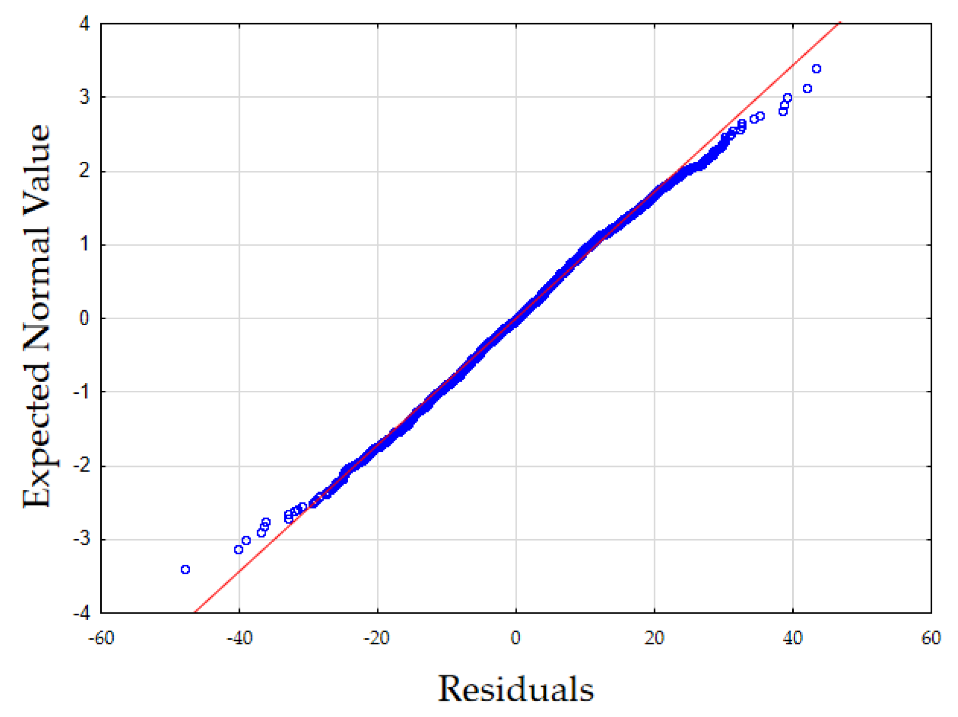
In Figure 2, the normality analysis of the distribution of the residuals was shown. It seems, Shapiro–Wilk test: SW–W = 0.9971, p = 0.0009. Variance constancy: fulfilled, the uniformity of the scatter of the residuals is constant across the width of the interval.
Simulations using the created MLR model confirmed the conclusions of the analysis of the balances performed, i.e., the predominance of chemical energy and the inverse proportionality of methane consumption to electrical energy consumption.
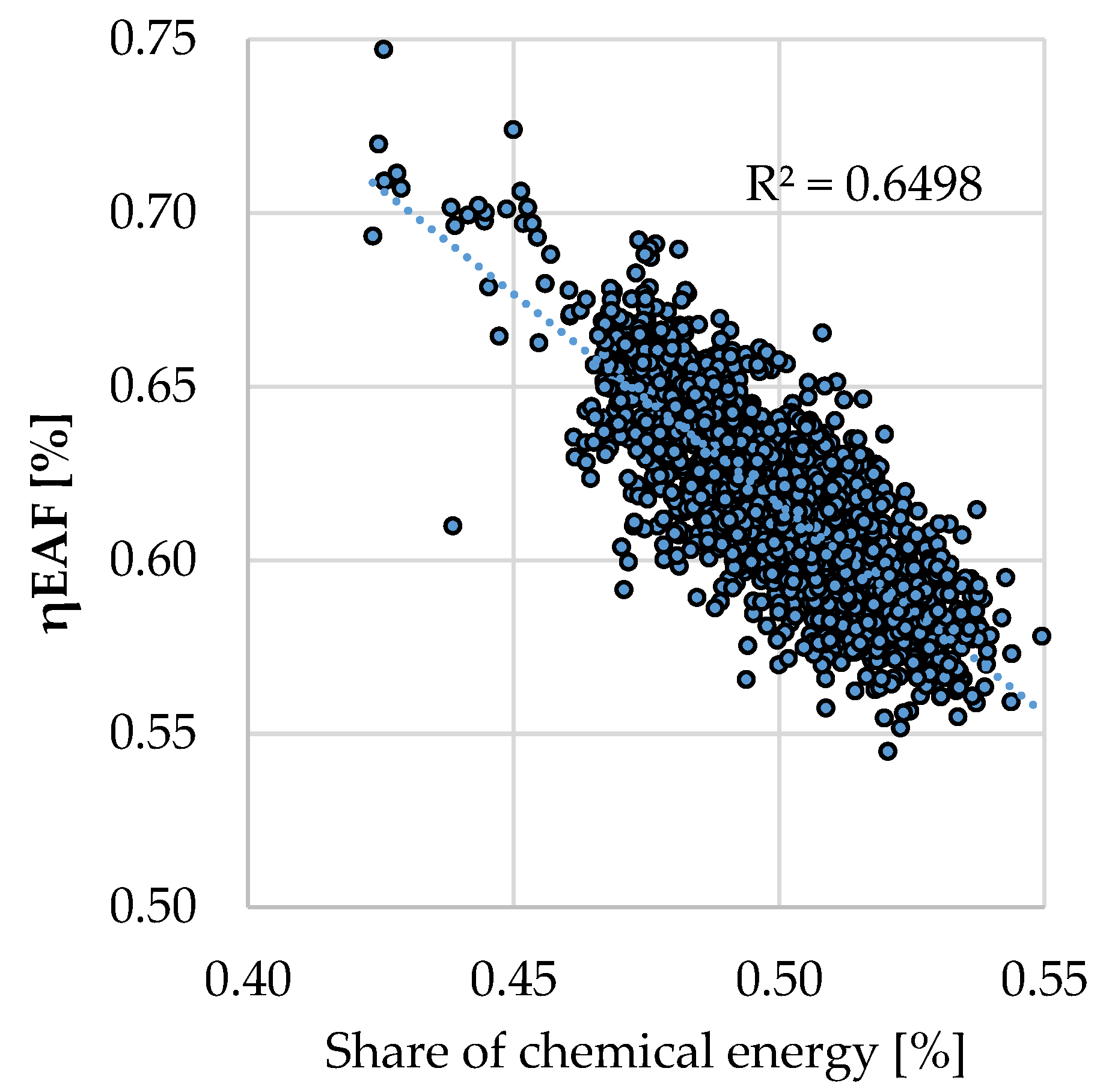
Taking into account the analysis results, which confirmed the conclusions of the mass and energy balance, the description of the process efficiency (defined as the ratio of the supplied energy to the amount of physical heat of the metal bath) as a function of the share of chemical energy was undertaken.
In Figure 3, the analysis of the dependence of process efficiency on the share of chemical energy was shown. A decrease in process efficiency (ηEAF) is visible with an increase in the share of chemical energy in the process. This trend in melt efficiency prompted an analysis of the efficiency of chemical energy use in the process under study.
As an example, the amount and timing of CH4 addition was analysed as a function of the efficiency of the heat generated by its combustion.
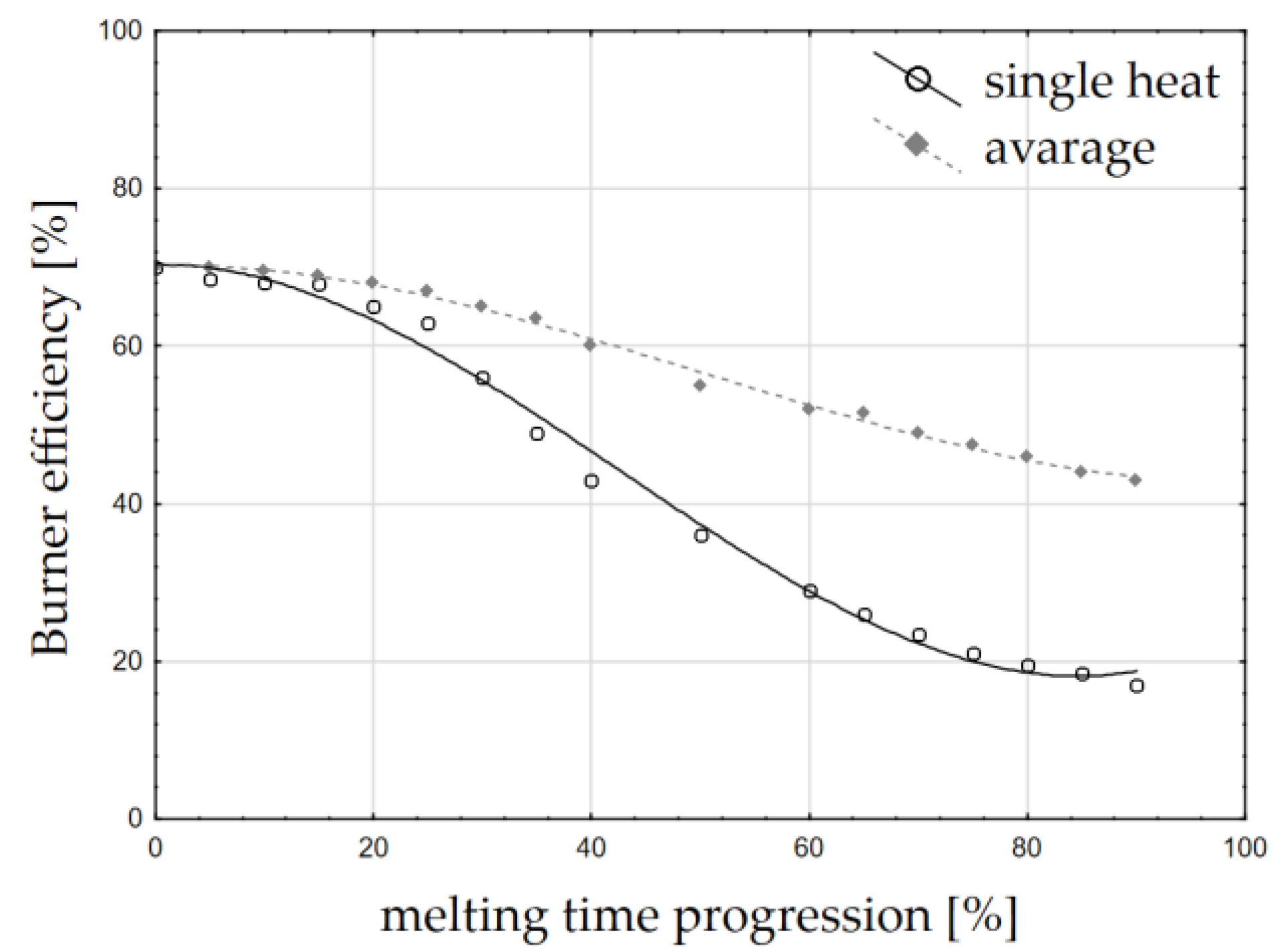
It was assumed that the efficiency will change with the progress of scrap melting. This is due to phenomena such as a change in the scrap surface with the progress of melting, but most importantly due to a decrease in the temperature difference between the flame and the charge, which heats up during the process. The change in burner efficiency was re-calculated on the basis of the approach presented in [21,24,25] and is presented in Figure 4.
The energy efficiency of the burners was considered first. This varies with the progress of melting. This efficiency is, on average, between 70 and 40%, and can drop as low as 20%. To identify the energy transfer efficiency, the Gottardi methodology was used [25], which made the energy efficiency of the burner dependent on, among other things, the temperature difference between the flame and the charge, which decreases with the progress of melting and, additionally, with a decrease in the scrap surface area. This dependence is described by the function (18):
η CH 4 = 70.272 8 · 10 3 · p t 2 + 5 · 10 5 · p t 3
where η CH 4 is the energy efficiency of the burner [%]; and pt is the melting progression [%].
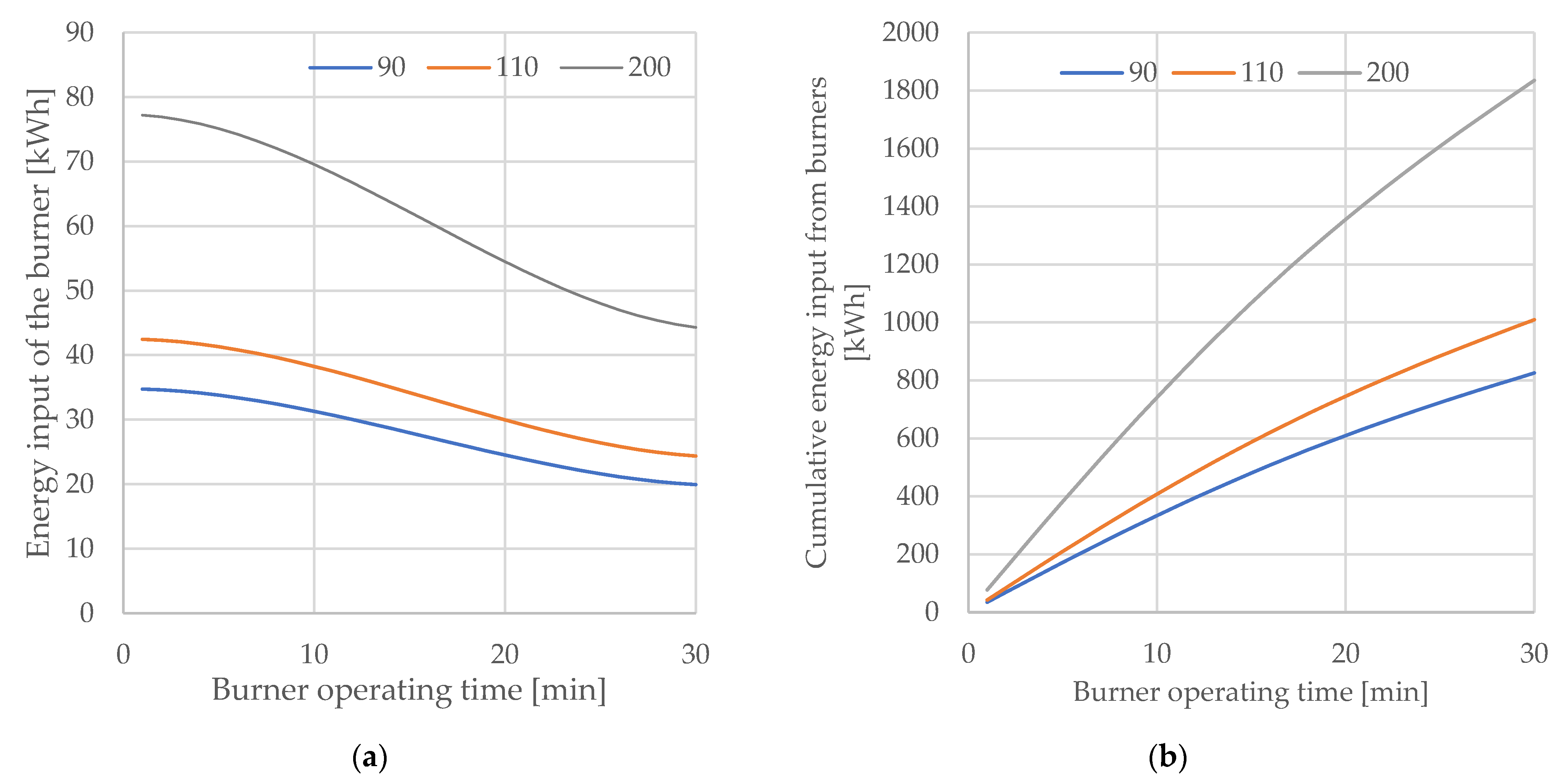
Based on the mathematical description of the change in burner efficiency as a function of melting progress, three patterns of energy gain as a function of the average gas flow possible under the conditions of the unit analysed were simulated. Boundary conditions were established: minimum gas flow in burner mode, 90 Nm3/h; the currently used average gas flow rate, 110 Nm3/h; and near-maximum flow rate, 200 Nm3/h. The maximum burner operation time—resulting from the melting stage characterised by the presence of scrap in the “cold regions” of the walls—is 30 min in total for all the baskets.
The change in energy contributed by the burners over time (Figure 4), the cumulative energy per 30 min (Figure 5a), and the cumulative energy as a function of the maximum possible amount of gas supplied (Figure 5b) were considered.
From the simulations obtained, it can be concluded that it is beneficial to intensify the gas flow in the initial stage of the melt, as this allows the burner to use its moment of greatest efficiency. The calculated maximum achievable gas consumption is, respectively, 135, 165, and 300 Nm3, and the energy contributed is 826 kWh, 1009 kWh, and 1835 kWh.
Finally, the equation was created to simulate production costs (in the sense of direct manufacturing costs), CO2 emissions, and process efficiency (Mg of hot metal/h)—it is assumed that such a construction of the model will allow to control the technology in a manner depending also on economic objectives.
The attempt to consolidate the results in terms of obtaining the unit melt cost function contributed to the creation of Equation (19).
P c = E el · X 1 + m CH 4 · X 2 + ( m scr m hm ) · X 4 + m ox · X 3 + ( m C + m CH 4 ) · 44 16 · X 5 + m sf · X 6
where Pc is the production cost; X1 is the cost per unit of electrical energy, PLN/kWh; X2 is the cost per unit of natural gas, PLN/Nm3; X3 is the cos per unit of technical oxygen, PLN/Nm3; X4 is the average unit cost of scrap purchase, PLN/Mg; X5 is the cost per emission of CO2 unit PLN/Mg; and X6 is the cost per unit of slag formers, PLN/kg.
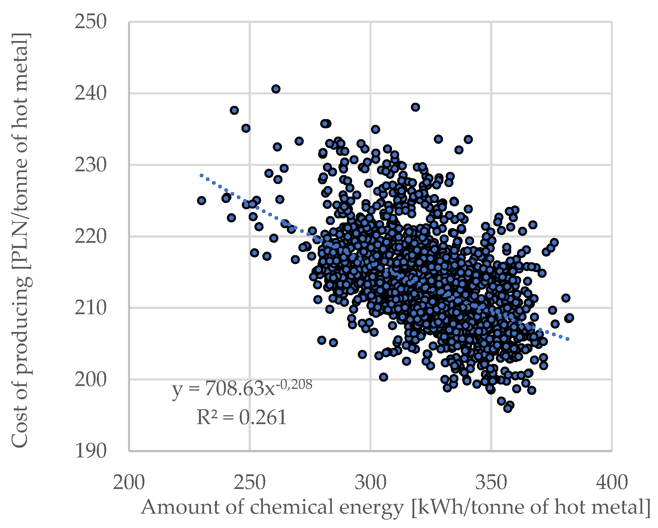
Equation (5) was used to calculate production costs (in terms of direct production costs of liquid steel), CO2 emissions, and process efficiency (Mg of hot metal/h)—assuming that such a model construction would allow to control the technology in a manner depending also on economic objectives. After calculating the production costs for the smelters under consideration (forming the database), a correlation analysis was carried out between the production cost (less the price of scrap metal forming the metal bath) and the amount of chemical energy input; the results are presented in Figure 6.
The correlation coefficient is R = 0.513 and the t-Student’s t-value reaches t = 41.51 with ttabular = 1.960. From the existence of this relationship (Figure 6) it should be concluded that it is advantageous to increase the share of chemical energy in the process, but taking into account the efficiency of its transfer by the oxygen treating bath stage.

4. Discussion

Modelling of the melting process in an electric arc furnace is possible under industrial conditions, even with incomplete metering. However, the individual characteristics of the unit under consideration have to be taken into account as existing models do not show universality. The use of models developed for other units requires their modification and taking into account the characteristics resulting from the proportion and share of chemical and electric energy as well as the input and technological conditions of the furnace.
Increasing the chemical energy input into the melt lowers the required total amount of electrical energy—methane consumption is inversely proportional to electrical energy consumption. However, due to the technological effect of the fact that oxygen is fed most intensively at the time of charge reheating—throughout this period—its correlation with electrical energy is positive.
Based on model calculations for the analysed furnace unit using a modified Köhle model from 2002, the model and actual data converged at the level of R = 0.36. The calculated electricity demand differed from the actual demand at the maximum level of 20%. However, it did not give sufficient guidance for process control.
Thanks to the mass and energy balance calculations performed, results were obtained from which it can be concluded that there is a predominance of chemical energy (52%) in the process compared to electrical energy.
It can be concluded that it is advantageous to intensify the gas flow at the initial stage of melting, as this makes it possible to use the moment of maximum efficiency of the burners (presented on Figure 5a,b). These conclusions require a complementary analysis; the real conditions of the process should be taken into account, which limit the maximum flow on the oxy–gas burners in the initial stages of the process (risk of burner damage by flame reflection from the scrap metal near the walls) and the fact that a higher energy input will lead to a faster melting of the deposited scrap metal
The statistical calculations carried out and the analyses of the statistical indices obtained made it possible to select the multiple linear regression model Equation (17)—as a method giving the possibility of an easy interpretation with an appropriate representation of the process in these conditions. The regression coefficient for the calculated model is R = 0.497, the difference between the calculated value and the real one is, at maximum, 17% (with mean 0). The obtained model was extended by the analysis of natural gas efficiency and consolidated with the cost calculation equation.

Author Contributions

Conceptualization, P.M. and M.K.; methodology, M.M.; resources, M.M.; data curation, M.M.; writing—original draft preparation, M.M.; writing—review and editing, P.M. and M.K. All authors have read and agreed to the published version of the manuscript.

Funding

This research received no external funding.

Institutional Review Board Statement

Not applicable.

Informed Consent Statement

Not applicable.

Data Availability Statement

Not applicable.

Acknowledgments

The present work was write as part of the second edition of “Implementation Doctorate” programme. The authors gratefully acknowledge their support.

Conflicts of Interest

The authors declare no conflict of interest.

References

  1. World Steel Association. Steel’s Contribution to a Low Carbon Future and Climate Resilient Societies—World Steel Position Paper; World Steel Association: Brussels, Belgium, 2020; ISBN 978-2-930069-83-8. Available online: https://www.worldsteel.org/en/dam/jcr:7ec64bc1-c51c-439b-84b8-94496686b8c6/Position_paper_climate_2020_vfinal.pdf (accessed on 10 November 2020).
  2. Carlsson, L.S.; Samuelsson, P.B.; Jönsson, P.G. Using Statistical Modeling to Predict the Electrical Energy Consumption of an Electric Arc Furnace Producing Stainless Steel. Metals 2020, 10, 36. [Google Scholar] [CrossRef] [Green Version]
  3. Sung, Y.; Lee, S.; Han, K.; Koo, J.; Lee, S.; Jang, D.; Oh, C.; Jang, B. Improvement of Energy Efficiency and Productivity in an Electric Arc Furnace through the Modification of Side-Wall Injector Systems. Processes 2020, 8, 1202. [Google Scholar] [CrossRef]
  4. Xiaojun, X.; Shufeng, Y.; Jingshe, L.; Jinqiang, W.; Mengjing, Z.; Maolin, Y. Physical model experiment and theoretical analysis of scrap melting process in electric arc furnace combined blowing system. Ironmak. Steelmak. 2020, 47, 748–756. [Google Scholar]
  5. Gharib Mombeni, A.; Hajidavalloo, E.; Behbahani-Nejad, M. Transient simulation of conjugate heat transfer in the roof cooling panel of an electric arc furnace. Appl. Therm. Eng. 2016, 98, 80–87. [Google Scholar] [CrossRef]
  6. Coskun, G.; Yiğit, C.; Buyukkaya, E. CFD modelling of a complete electric arc furnace energy sources. Innovations 2016, 4, 22–24. [Google Scholar]
  7. He, K.; Wang, L.; Li, X. Review of the Energy Consumption and Production Structure of China’s Steel Industry: Current Situation and Future Development. Metals 2020, 10, 302. [Google Scholar] [CrossRef] [Green Version]
  8. Faraway, J.J. Generalized linear models. In International Encyclopedia of Education, 3rd ed.; Peterson, P., Baker, E., McGaw, B., Eds.; Elsevier: Amsterdam, The Netherlands, 2010; pp. 178–183. [Google Scholar] [CrossRef]
  9. Cameron, L.T.; Hangos, K.M. Process Modelling and Model Analysis, 1st ed.; Academic Press: San Diego, CA, USA, 2001; Volume 4, pp. 10–17; 253–275. [Google Scholar]
  10. Haupt, M.; Vadenbo, C.; Zeltner, C.; Hellweg, S. Influence of Input-Scrap Quality on the Environmental Impact of Secondary Steel Production. J. Ind. Ecol. 2017, 21, 391–401. [Google Scholar] [CrossRef]
  11. Morales, R.D.; Rodriguez, H.; Conejo, A.N. A Mathematical Simulator for the EAF Steelmaking Process Using Direct Reduced Iron. ISIJ Int. 2001, 41, 426–436. [Google Scholar] [CrossRef]
  12. Bekker, J.G.; Craig, I.K.; Pistorius, P.C. Modeling and Simulation of an Electric Arc Furnace Process. ISIJ Int. 1999, 39, 23–32. [Google Scholar] [CrossRef] [Green Version]
  13. Logar, V.; Dovžan, D.; Škrjanc, I. Modeling and Validation of an Electric Arc Furnace Part 1, Heat and Mass Transfer. ISIJ Int. 2012, 52, 402–412. [Google Scholar] [CrossRef] [Green Version]
  14. Logar, V.; Dovžan, D.; Škrjanc, I. Modeling and Validation of an Electric Arc Furnace Part 2, Thermo-chemistry. ISIJ Int. 2021, 52, 413–423. [Google Scholar] [CrossRef] [Green Version]
  15. Štrumbelj, E.; Kononenko, I. A General Method for Visualizing and Explaining Black-Box Regression Models. In Adaptive and Natural Computing Algorithms; ICANNGA 2011; Lecture Notes in Computer Science; Dobnikar, A., Lotrič, U., Šter, B., Eds.; Springer: Berlin, Germany, 2011; Volume 6594, pp. 21–30. [Google Scholar]
  16. Banks, H.T.; Tran, H.T. Mathematical and Experimental Modeling of Physical and Biological Processes, 1st ed.; Chapman and Hall/CRC: New York, NY, USA, 2009; pp. 3–5. [Google Scholar]
  17. Carlsson, L.S.; Samuelsson, P.B.; Jönsson, P.G. Predicting the Electrical Energy Consumption of Electric Arc Furnaces Using Statistical Modeling. Metals 2019, 9, 959. [Google Scholar] [CrossRef] [Green Version]
  18. Köhle, S. Effects on the electric energy and electrode consumption of arc furnaces. Stahl Eisen 1992, 112, 59–67. [Google Scholar]
  19. Köhle, S.; Lichterbeck, R.; Paura, G. Verbesserung der Energetischen Betriebsführung von Drehstrom-Lichtbogenöfen; European Commission: Brussels, Belgium, 1996. [Google Scholar]
  20. Meier, T.; Gandt, K.; Echterhof, T.; Pfeifer, H. Modeling and Simulation of the Off-gas in an Electric Arc Furnace. Metall. Mater. Trans. B 2017, 48, 3329–3344. [Google Scholar] [CrossRef] [Green Version]
  21. Karbowniczek, M. Electric Arc Furnace Steelmaking, 1st ed.; CRC Press Taylor & Francis Group: Boca Raton, FL, USA, 2021; p. 239. [Google Scholar]
  22. Köhle, S. Recent improvements in modelling energy consumption of electric arc furnaces. In Proceedings of the 7th European Electric Steelmaking Conference, Venice, Italy, 26–29 May 2002. [Google Scholar]
  23. Migas, P.; Moskal, M.; Karbowniczek, M.; Czyż, J. Analysis of the energy consumption during the electric arc process. In Proceedings of the Iron and Steelmaking 2019, Modern Metallurgy the XXVIII International Scientific Conference, Liptovský Mikuláš, Slovakia, 23–25 October 2019. [Google Scholar]
  24. Pretorius, E.; Oltmann, H.; Jones, J. EAF Fundamentals: Charging, Melting and Refining; LWB Refractories: New York, NY, USA, 2005; pp. 16–21. [Google Scholar]
  25. Bergman, K.; Gottardi, R. Design criteria for the modern UHP electric arc furnace with auxiliaries. Ironmak. Steelmak. 1990, 17, 282–287. [Google Scholar]
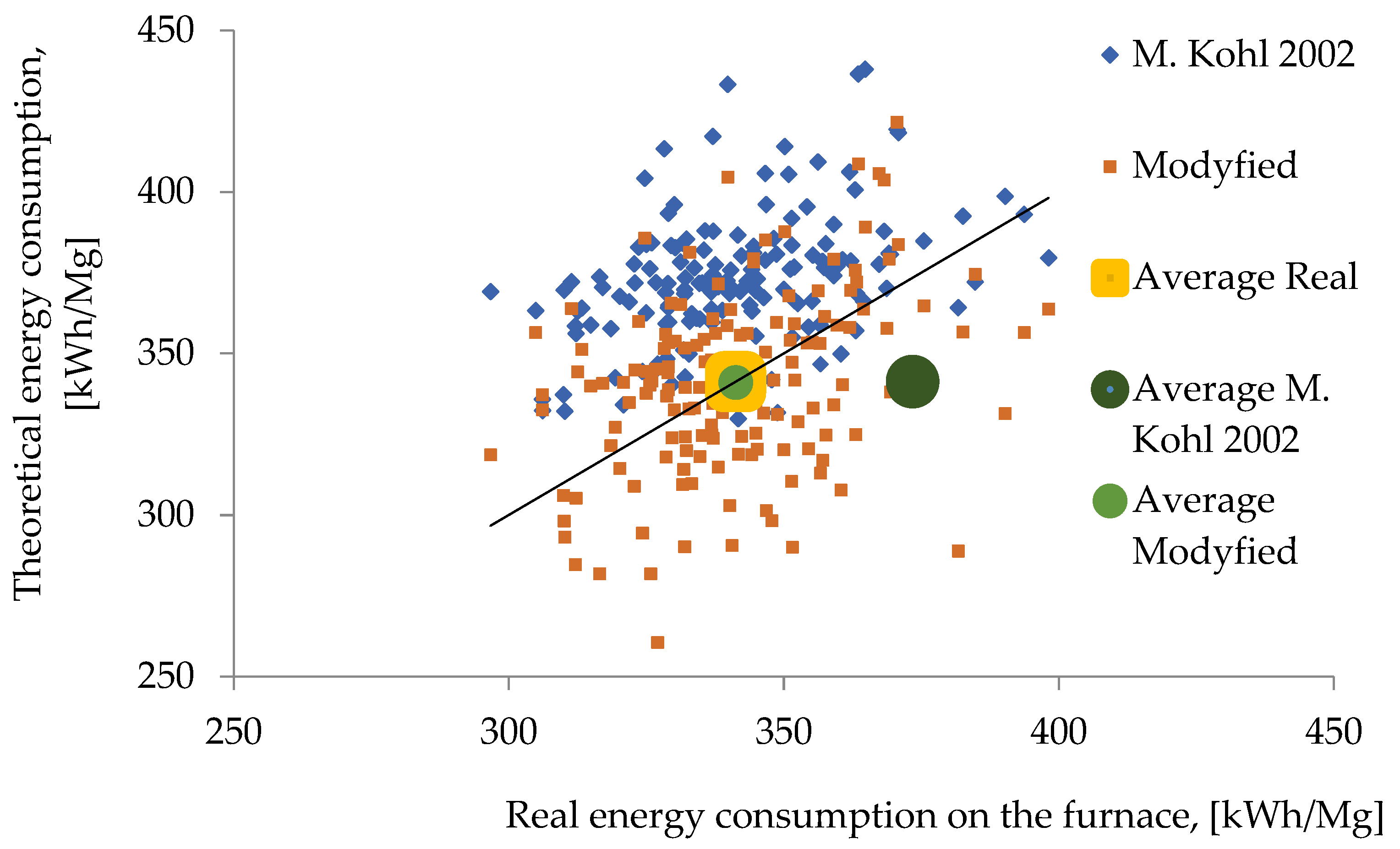
Figure 1. Comparison of Köhle model results with real electricity consumption [23].
Materials 15 01601 g001
Figure 2. Normal distribution of residuals.
Materials 15 01601 g002
Figure 3. Dependence of process efficiency on the share of chemical energy.
Materials 15 01601 g003
Figure 4. Burner efficiency as a function of melting time progression [%] (own study based on data from [21]).
Materials 15 01601 g004
Figure 5. (a) Variation of burner energy input as a function of burner operating time (b) cumulative energy as a function of burner operating time
Materials 15 01601 g005
Figure 6. The amount of chemical energy in relation to the direct cost of producing a tonne of metal bath.
Materials 15 01601 g006
Table 1. Temperature reduction factor for individual elements [21].
ElementCMgSiPSCuNiVMoCr
ki6558302554221.5
Table 2. Average chemical composition of EAF slags before tap.
OxideCaOMgOMnOCr2O3SiO2P2O5Al2O3TiO2FeO
% of weight29.545.719.097.529.550.411.190.4236.57
Table 3. Average chemical composition of liquid bath before tap.
ElementCMnCrNiSiPS
% of mass0.0710.0830.1070.1090.0050.0080.107
Table 4. Statistical parameters of calculated MLR model.
Variableb*Std. Err. of b*BStd. Err. of bt(1953)p-Value
Intercept 169.9428.68919.5580.000
Tap-to-tap time0.2480.0200.2630.02112.3240.000
Oxygen to charge0.4030.02032710.16619.6700.000
Natural gas to charge−0.0550.020−26330.952−27670.006
Slag formers to charge0.0640.0200.1130.03631660.002
Scrap yield0.1230.02148.7878.3775.820.000
b* is a structural parameters of the regression function; B is an estimators of obtained regression equation; t is a t-Student test probability distribution; and p-value is a probability level of variable.
Publisher’s Note: MDPI stays neutral with regard to jurisdictional claims in published maps and institutional affiliations.