
Magnetic Investigation of Cladded Nuclear Reactor Blocks


Abstract
:1. Introduction
2. Materials and Methods
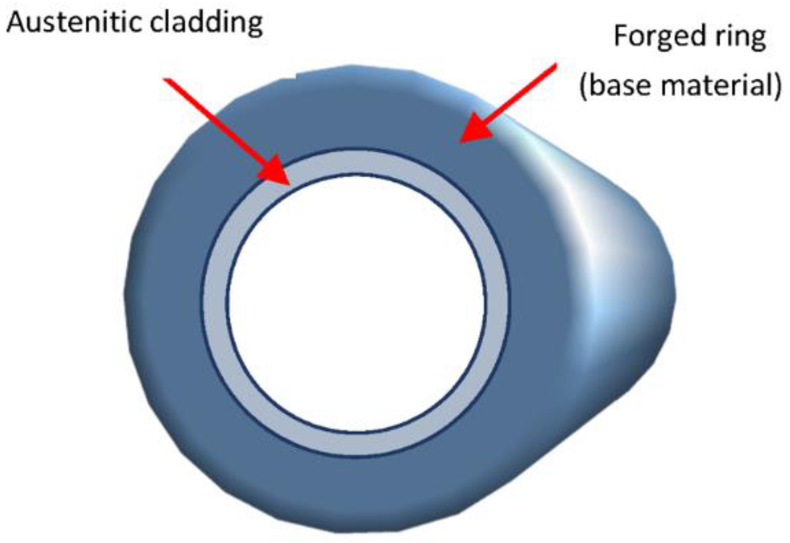
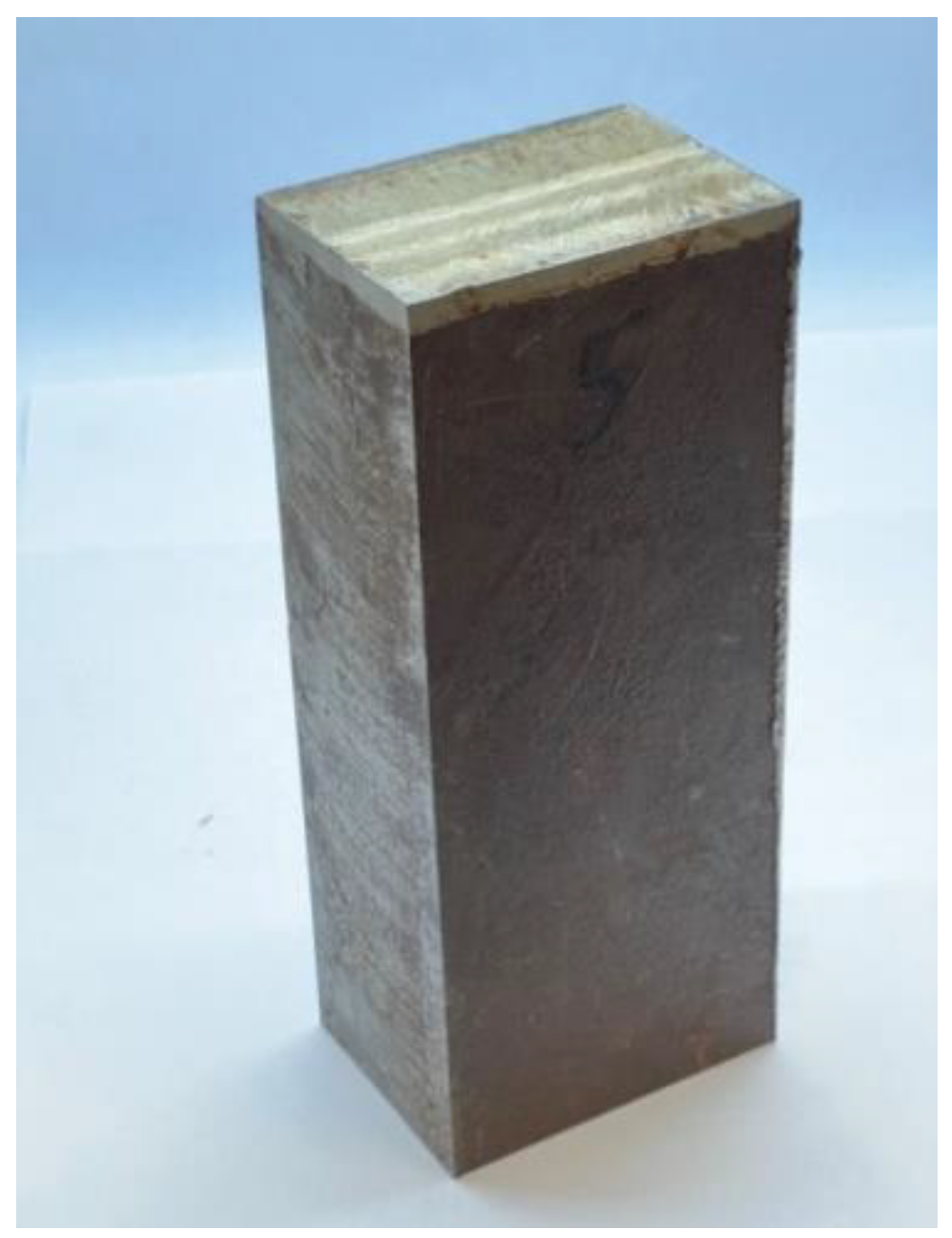
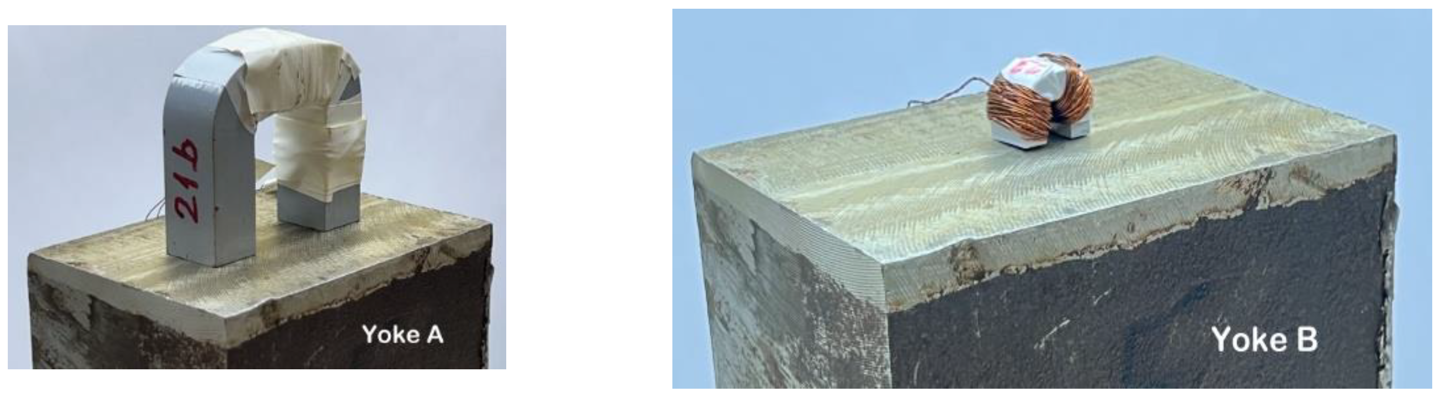
2.1. Materials
2.2. Magnetic Measurement
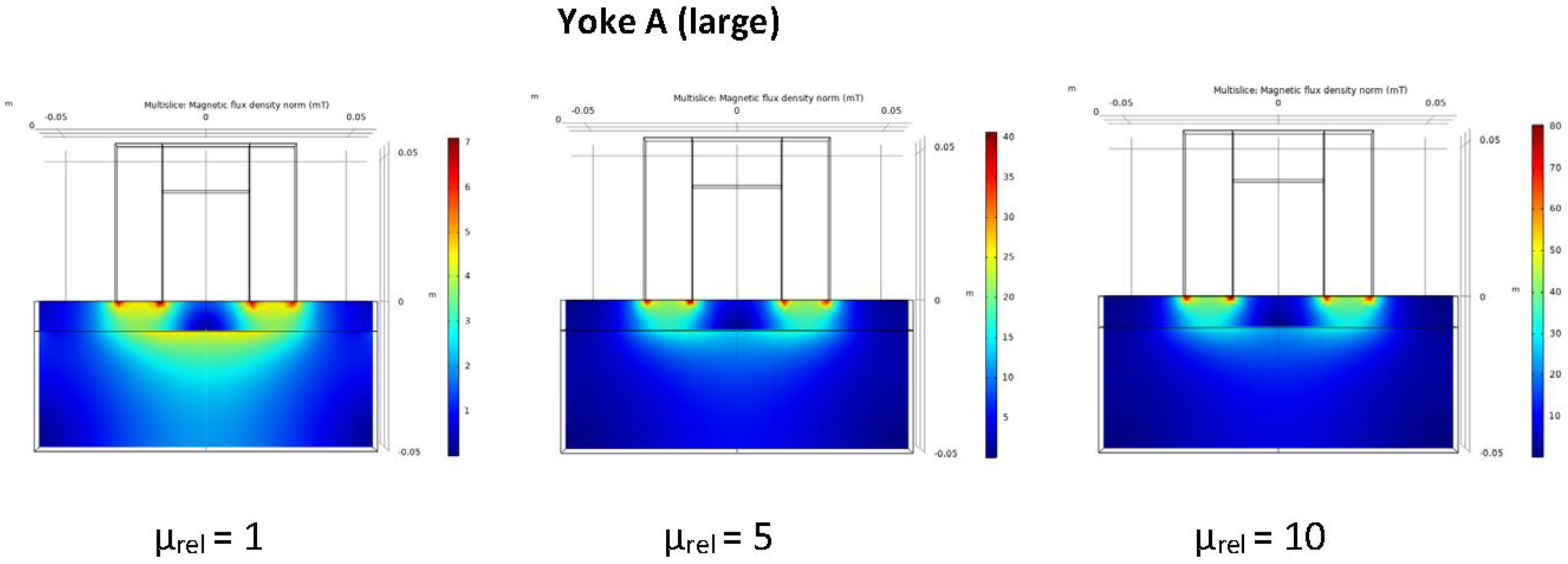
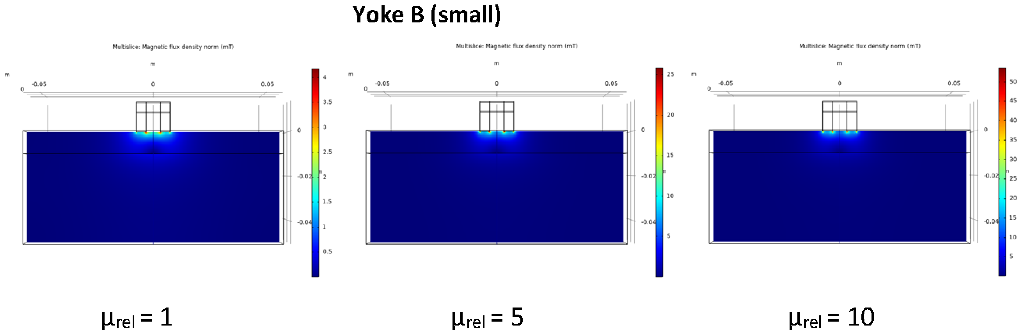
2.3. Numerical Simulation
3. Results and Discussion
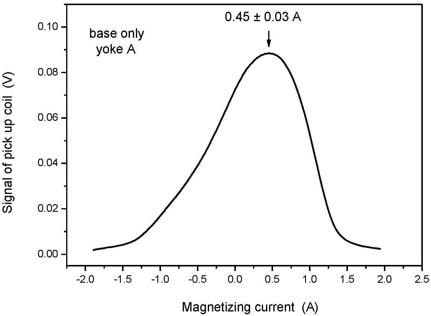
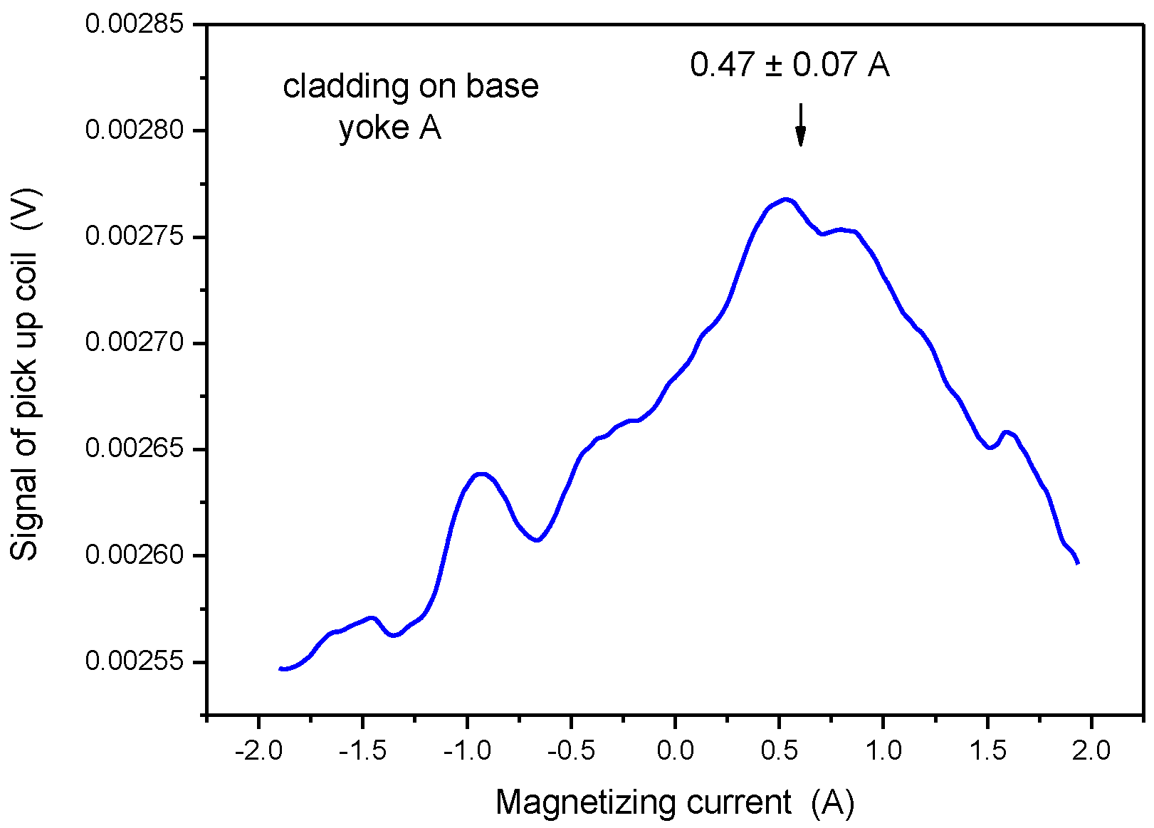
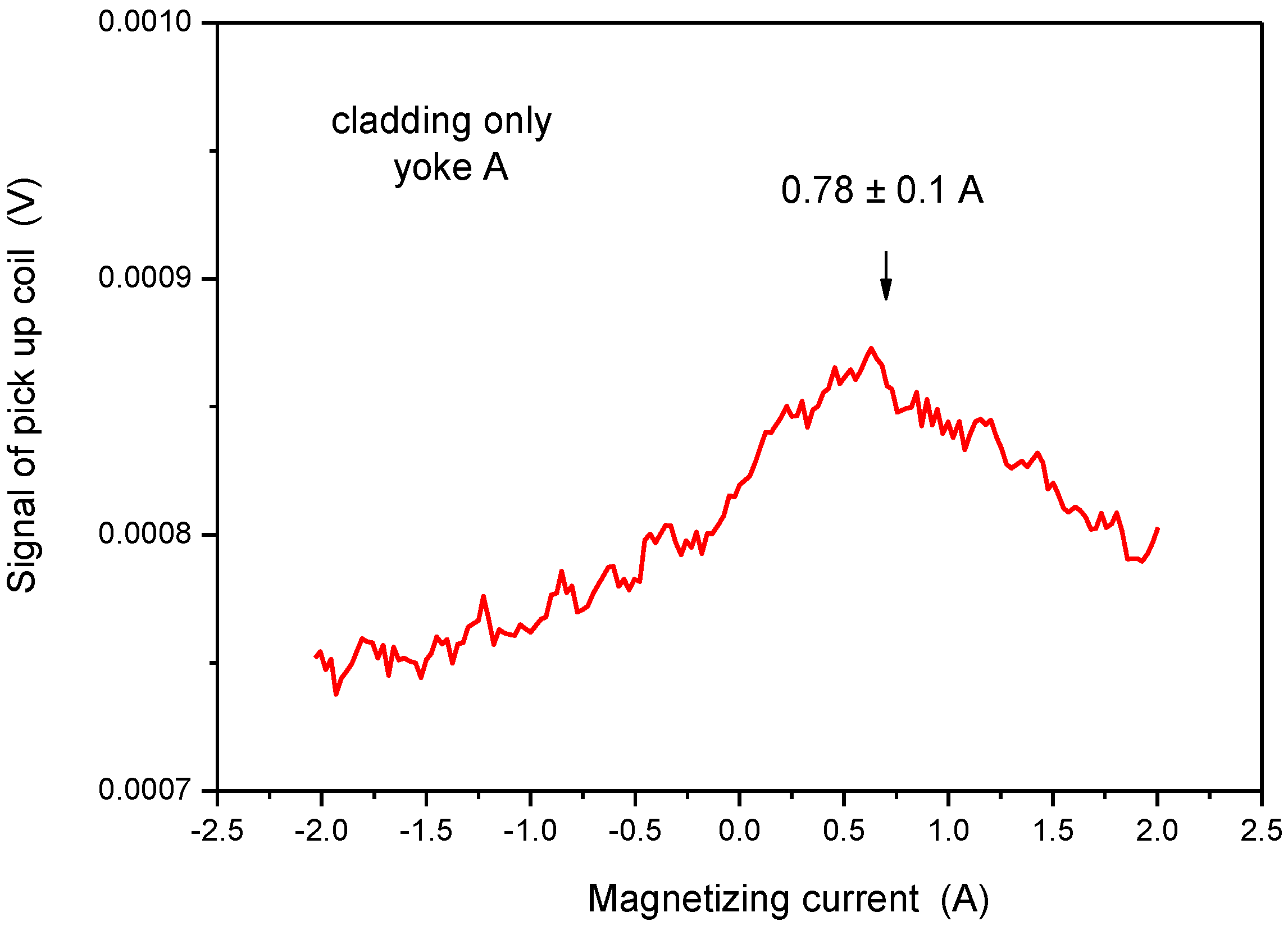
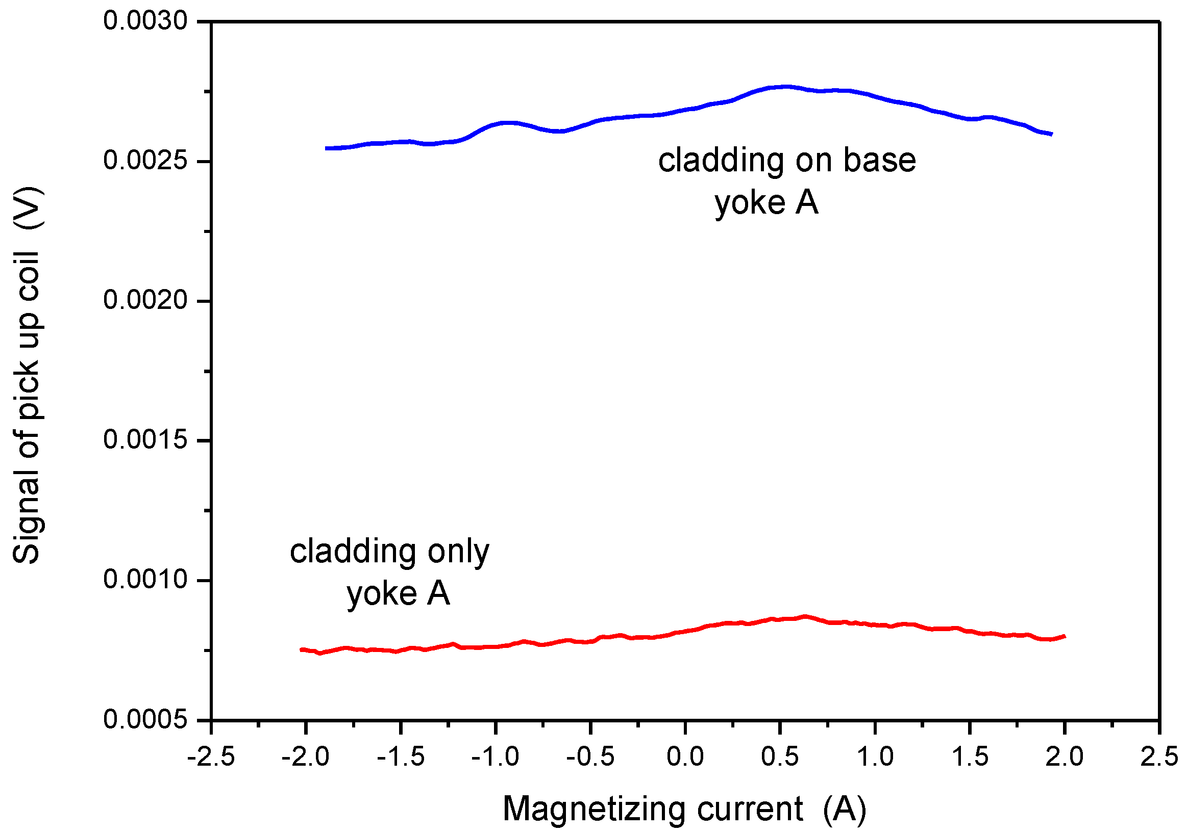
3.1. Yoke A
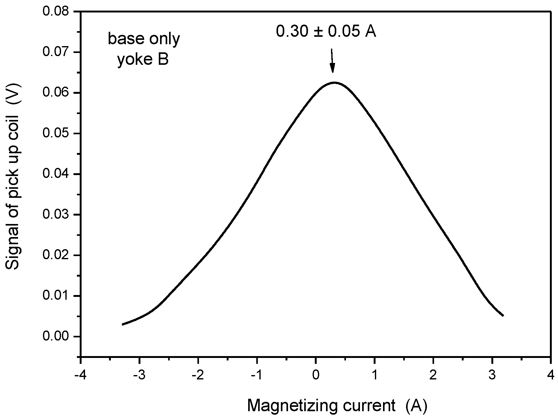
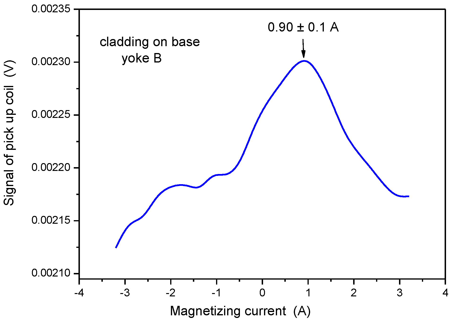
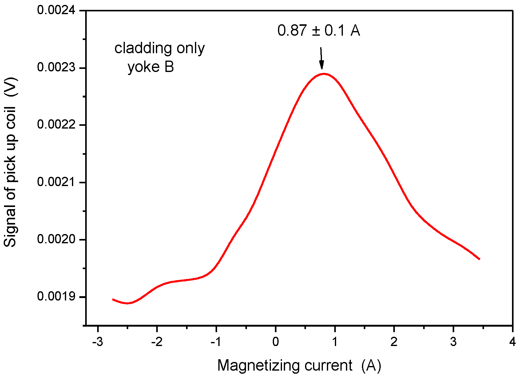
3.2. Yoke B
4. Conclusions
Author Contributions
Funding
Institutional Review Board Statement
Informed Consent Statement
Data Availability Statement
Conflicts of Interest
References
- The Economics of Long-Term Operation of Nuclear Power Plants; Nuclear Energy Agency and Organisation for Economic Co-Operation and Development: Paris, France, 2012.
- Ballesteros, A.; Ahlstrand, R.; Bruynooghe, C.; von Estorff, U.; Debarberis, L. The role of pressure vessel embrittlement in the long term operation of nuclear power plants. Nucl. Eng. Des. 2012, 243, 63–68. [Google Scholar] [CrossRef]
- Al Mazouzi, A.; Alamo, A.; Lidbury, D.; Moinereau, D.; Van Dyck, S. PERFORM 60: Prediction of the effects of radiation for reactor pressure vessel and in-core materials using multi-scale modelling—60 years foreseen plant lifetime. Nucl. Eng. Des. 2011, 241, 3403–3415. [Google Scholar] [CrossRef]
- Koutsky, J.; Kocık, J. Radiation Damage of Structural Materials; Elsevier: Amsterdam, The Netherlands, 1994. [Google Scholar]
- Ferreño, D.; Gorrochategui, I.; Gutiérrez-Solana, F. Degradation due to neutron embrittlement of nuclear vessel steels: A critical review about the current experimental and analytical techniques to characterise the material, with particular emphasis on alternative methodologies. In Nuclear Power—Control, Reliability and Human Factors; Tsvetkov, P., Ed.; IntechOpen Limited: London, UK, 2011; ISBN 9789533075990. Available online: http://www.intechopen.com/articles/show/title/non-destructive-testing-for-ageing-management-of-nuclear-power-component (accessed on 20 October 2019).
- Niffenegger, M.; Leber, H.J. Monitoring the embrittlement of reactor pressure vessel steels by using the Seebeck coefficient. J. Nucl. Mater. 2009, 389, 62. [Google Scholar] [CrossRef]
- Niffenegger, M.; Reichlin, K.; Kalkhof, D. Application of the Seebeck effect for monitoring of neutron embrittlement and low-cycle fatigue in nuclear reactor steel. Nucl. Eng. Des. 2005, 235, 1777–1788. [Google Scholar] [CrossRef]
- Seiler, G. Early detection of fatigue at elevated temperature in austenitic steel using electromagnetic ultrasound transducers. In Proceedings of the Seventh International Conference on Low Cycle Fatigue: LCF7, Deutscher Verband für Materialforschung und-prüfung e.V. (DVM), Aachen, Germany, 9–11 September 2013; pp. S359–S364. [Google Scholar]
- Smith, R.L.; Rusbridge, K.L.; Reynolds, W.N.; Hudson, B. Ultrasonic attenuation, microstructure and ductile to brittle transition temperature in Fe-C alloys. Mater. Eval. 1993, 41, 219–222. [Google Scholar]
- Dobmann, G.; Kröning, M.; Theiner, W.; Willems, H.; Fiedler, U. Nondestructive characterization of materials (ultrasonic and magnetic techniques) for strength and toughness prediction and the detection early creep damage. Nucl. Eng. Des. 1995, 157, 137–158. [Google Scholar] [CrossRef]
- Jiles, D.C. Magnetic methods in nondestructive testing. In Encyclopedia of Materials Science and Technology; Buschow, K.H.J., Ed.; Elsevier: Oxford, UK, 2001; p. 6021. [Google Scholar]
- Blitz, J. Electrical and Magnetic Methods of Nondestructive Testing; Adam Hilger IOP Publishing, Ltd.: Bristol, UK, 1991. [Google Scholar]
- Lo, C.C.H.; Jakubovics, J.P.; Scrub, C.B. Non-destructive evaluation of spheroidized steel using magnetoacoustic and Barkhausen emission. IEEE Trans. Magn. 1997, 33, 4035–4037. [Google Scholar] [CrossRef]
- Kikuchi, H.; Ara, K.; Kamada, Y.; Kobayashi, S. Effect of microstructure changes on Barkhausen noise properties and hysteresis loop in cold rolled low carbon steel. IEEE Trans. Magn. 2009, 45, 2744–2747. [Google Scholar] [CrossRef]
- Hartmann, K.; Moses, A.J.; Meydan, T. A system for measurement of AC Barkhausen noise in electrical steels. J. Magn. Magn. Mater. 2003, 254–255, 318–320. [Google Scholar] [CrossRef]
- Barroso, S.P.; Horváth, M.; Horváth, Á. Magnetic measurements for evaluation of radiation damage on nuclear reactor materials. Nucl. Eng. Des. 2010, 240, 722–725. [Google Scholar] [CrossRef]
- Augustyniak, B.; Chmielewski, M.; Piotrowski, L.; Kowalewski, Z. Comparison of properties of magnetoacoustic emission and mechanical barkhausen effects for P91 steel after plastic flow and creep. IEEE Trans. Magn. 2008, 44, 3273–3276. [Google Scholar] [CrossRef]
- Devine, M.K. Magnetic detection of material properties. J. Min. Met. Mater. JOM 1992, 44, 24–30. [Google Scholar] [CrossRef]
- Kronmüller, H.; Fähnle, M. Micromagnetism and the Microstructure of Ferromagnetic Solids; Cambridge University Press: Cambridge, UK, 2003. [Google Scholar]
- Dobmann, G.; Altpeter, I.; Kopp, M.; Rabung, M.; Hubschen, G. ND-materials characterization of neutron induced embrittlement in German nuclear reactor pressure vessel material by micromagnetic NDT techniques. In Electromagnetic Nondestructive Evaluation (XI); IOS Press: Amsterdam, The Netherlands, 2008; p. 54. ISBN 978-1-58603-896-0. [Google Scholar]
- Altpeter, I.; Becker, R.; G Dobmann, R.; Kern, W.A.; Theiner, A. Yashan: Robust Solutions of Inverse Problems in Eletromagnetic Non-Destructive Evaluation. Inverse Probl. 2002, 18, 1907–1921. [Google Scholar] [CrossRef]
- Szielasko, K.; Wolter, B.; Tschuncky, R.; Youssef, S. Micromagnetic materials characterization using maschin learning—Progress in Nondestructive Prediction of Mechanical Properties of Steel and Iron. Tech. Mess. 2020, 87, 428–437. [Google Scholar] [CrossRef]
- Takahashi, S.; Kobayashi, S.; Kikuchi, H.; Kamada, Y. Relationship between mechanical and magnetic properties in cold rolled low carbon steel. J. Appl. Phys. 2006, 100, 113908. [Google Scholar] [CrossRef] [Green Version]
- Tomáš, I. Non-destructive Magnetic Adaptive Testing of ferromagnetic materials. J. Mag. Mag. Mat. 2004, 268, 178–185. [Google Scholar] [CrossRef]
- Vértesy, G.; Gasparics, A.; Uytdenhouwen, I.; Szenthe, I.; Gillemot, F.; Chaouadi, R. Nondestructive investigation of neutron irradiation generated structural changes of reactor steel material by magnetic hysteresis method. Metals 2020, 10, 642. [Google Scholar] [CrossRef]
- Tomáš, I.; Vértesy, G.; Gillemot, F.; Székely, R. Nondestructive Magnetic Adaptive Testing of Nuclear Reactor Pressure Vessel Steel Degradation. J. Nucl. Mater. 2013, 432, 371–377. [Google Scholar] [CrossRef]
- Rabung, M.; Kopp, M.; Gasparics, A.; Vértesy, G.; Szenthe, I.; Uytdenhouwen, I. Micromagnetic characterization of operation induced damage in Charpy specimens of RPV steels. Appl. Sci. 2021, 11, 2917. [Google Scholar] [CrossRef]
- Gillemot, F. Overview of Reactor Pressure Vessel Cladding. Int. J. Nucl. Knowl. Manag. 2010, 4, 265–278. [Google Scholar] [CrossRef]
- Vértesy, G.; Gasparics, A.; Szenthe, I.; Gillemot, F. Magnetic nondestructive inspection of reactor steel cladded blocks. Glob. J. Adv. Eng. Technol. Sci. 2019, 6, 1. [Google Scholar]
- Gillemot, F.; Horváth, M.; Úri, G.; Fekete, T.; Houndeffo, E.; Acosta, B.; Debarberis, L.; Viehrig, H.W. Radiation Stability of WWER RPV Cladding Materials. Int. J. Press. Vessel. Pip. 2007, 84, 469–474. [Google Scholar] [CrossRef]
- Trampus, P. Pressurized Thermal Shock Analysis of the Reactor Pressure Vessel. Procedia Struct. Integr. 2018, 13, 2083–2088. [Google Scholar] [CrossRef]
- Chen, M.; Yu, W.; Qian, G.; Shi, J.; Cao, Y.; Yu, Y. Crack Initiation, Arrest and Tearing Assessments of a RPV Subjected to PTS Events. Ann. Nucl. Energy 2018, 116, 143–151. [Google Scholar] [CrossRef]
- Štefan, J.; Siegl, J.; Adámek, J.; Kopřiva, R.; Falcník, M. Microstructure and Failure Processes of Reactor Pressure Vessel Austenitic Cladding. Metals 2021, 11, 1676. [Google Scholar] [CrossRef]
- Comsol Multiphysics. AC/DC Module User’s Guide. Available online: https://doc.comsol.com/5.4/doc/com.comsol.help.acdc/ACDCModuleUsersGuide.pdf (accessed on 10 January 2022).
- Vértesy, G.; Tomáš, I.; Mészáros, I. Nondestructive indication of plastic deformation of cold-rolled stainless steel by magnetic adaptive testing. J. Magn. Magn. Mater. 2007, 310, 76–82. [Google Scholar] [CrossRef]
- Vértesy, G.; Ueda, S.; Uchimoto, T.; Takagi, T.; Tomáš, I.; Vértesy, Z. Evaluation of Plastic Deformation in Steels by Magnetic Hysteresis Measurements. In Elecstromagnetic Nondestructive Evaluation (XIV); Takagi, T., Udpa, S.S., Chady, T., Gratkowski, S., Eds.; IOS Press: Amsterdam, The Netherlands, 2011; pp. 371–378. [Google Scholar]


| C% | Mn% | Si% | S% | P% | Cr% | Ni% | Mo% | V% | Cu% | Co% | Sb% | Sn | As% |
|---|---|---|---|---|---|---|---|---|---|---|---|---|---|
| 0.16 | 0.42 | 0.29 | 0.08 | 0.012 | 1.97 | 1.29 | 0.52 | 0.12 | 0.12 | 0.06 | 0.001 | 0.003 | 0.003 |
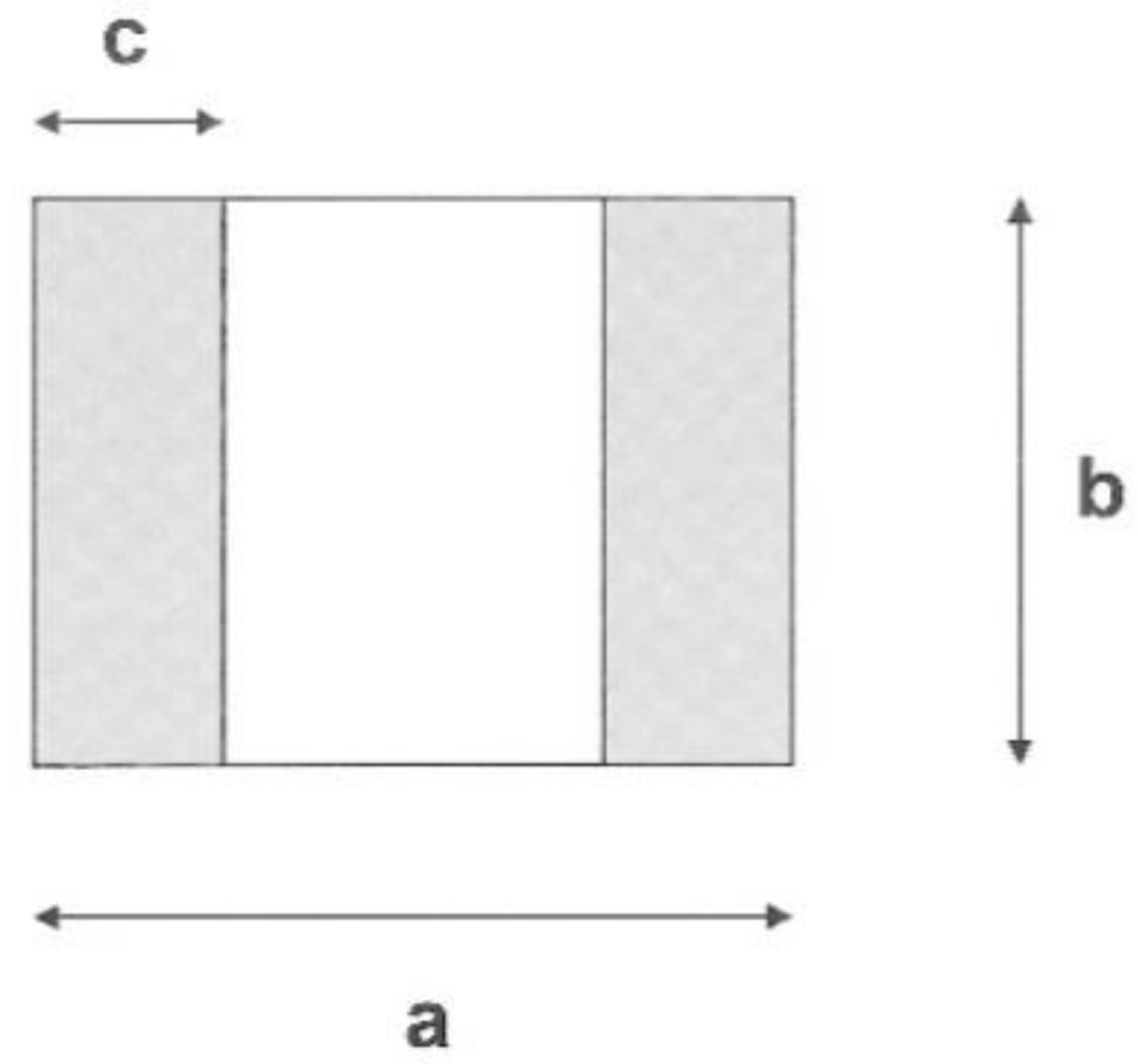
| a (mm) | b (mm) | c (mm) | Height (mm) | |
|---|---|---|---|---|
| Yoke A | 62.0 | 19.0 | 16.0 | 55.0 |
| Yoke B | 11.5 | 12.5 | 4.5 | 13.0 |
| μrel | Ψ1 (Wb) | Ψ2 (Wb) | Ψ2/Ψ1 | |
|---|---|---|---|---|
| Yoke A | 1 | 4.55 × 10⁻⁶ | 4.24 × 10⁻⁶ | 0.931 |
| Yoke A | 5 | 1.49 × 10⁻⁵ | 1.43 × 10⁻⁵ | 0.956 |
| Yoke A | 10 | 2.54 × 10⁻⁵ | 2.43 × 10⁻⁵ | 0.955 |
| Yoke B | 1 | 3.35 × 10⁻⁷ | 1.96 × 10⁻⁷ | 0.586 |
| Yoke B | 5 | 1.12 × 10⁻⁶ | 5.88 × 10⁻⁷ | 0.526 |
| Yoke B | 10 | 1.95 × 10⁻⁶ | 9.86 × 10⁻⁷ | 0.505 |
Publisher’s Note: MDPI stays neutral with regard to jurisdictional claims in published maps and institutional affiliations. |
© 2022 by the authors. Licensee MDPI, Basel, Switzerland. This article is an open access article distributed under the terms and conditions of the Creative Commons Attribution (CC BY) license (https://creativecommons.org/licenses/by/4.0/).
Share and Cite
Vértesy, G.; Gasparics, A.; Szenthe, I.; Bilicz, S. Magnetic Investigation of Cladded Nuclear Reactor Blocks. Materials 2022, 15, 1425. https://doi.org/10.3390/ma15041425
Vértesy G, Gasparics A, Szenthe I, Bilicz S. Magnetic Investigation of Cladded Nuclear Reactor Blocks. Materials. 2022; 15(4):1425. https://doi.org/10.3390/ma15041425
Chicago/Turabian StyleVértesy, Gábor, Antal Gasparics, Ildikó Szenthe, and Sándor Bilicz. 2022. "Magnetic Investigation of Cladded Nuclear Reactor Blocks" Materials 15, no. 4: 1425. https://doi.org/10.3390/ma15041425
APA StyleVértesy, G., Gasparics, A., Szenthe, I., & Bilicz, S. (2022). Magnetic Investigation of Cladded Nuclear Reactor Blocks. Materials, 15(4), 1425. https://doi.org/10.3390/ma15041425