
Optimisation of Thermal Processes with Plasma Nitriding on Vanadis 4 High Speed Steel

 , ,
, ,
Abstract
1. Introduction
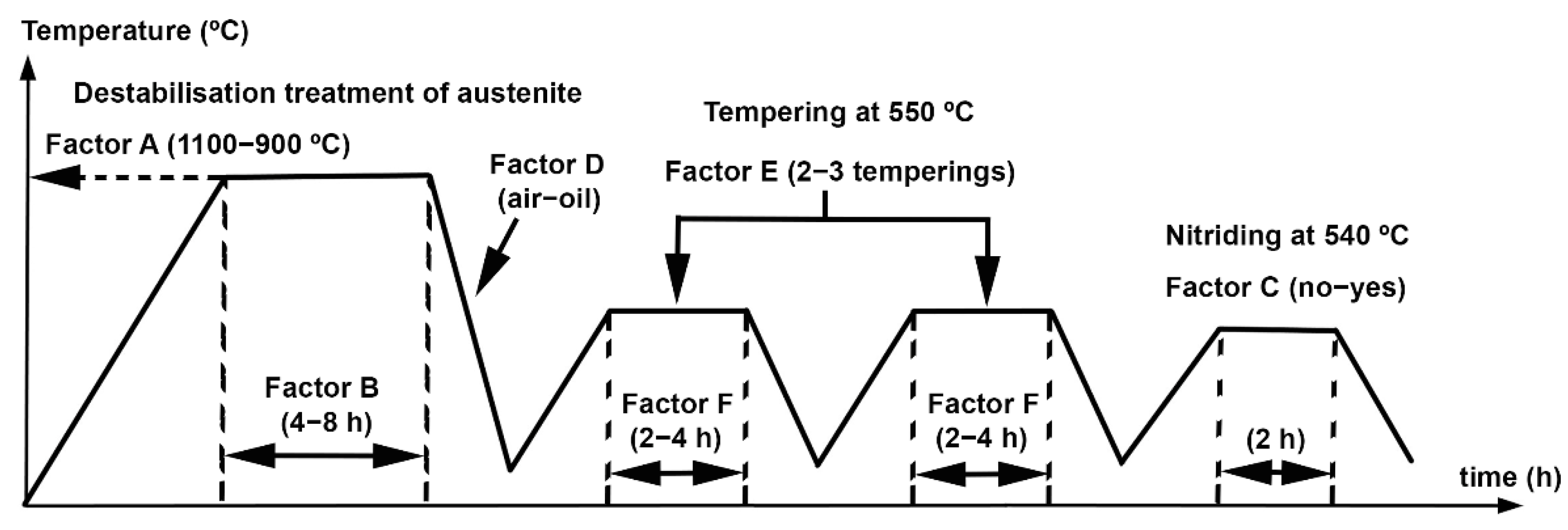
2. Materials and Methods
- The following microstructural variables:
- ⚬
- Weight percentage of tempered martensite
- ⚬
- Weight percentage of retained austenite
- ⚬
- Weight percentage of the carbides M7C3 and MC
- Vickers hardness before nitriding. The load applied was of 300 N and the estimated hardness value in each experiment was of an average value obtained as from 12 hardness indentations.
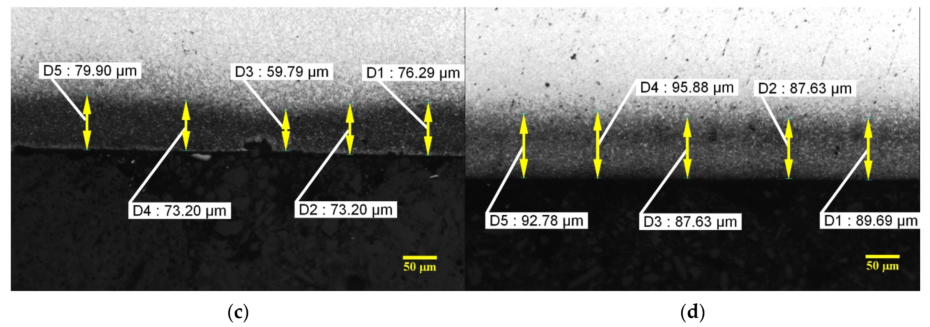
- Knoop hardness of the nitride layer in experiments 5 to 8. The load applied was of 0.5 N. The average estimated hardness value as from 12 hardness indentations carried out along the thickness of the nitrided layer.
- The resistance to wear with a pin-on-disc test with a linear speed of 0.15 m/s and a load of 30 N. A ball of WC (with 6% Co) of 5 mm in diameter and a hardness of 1660 HV acted as the pin. The total distance travelled was 4 km.
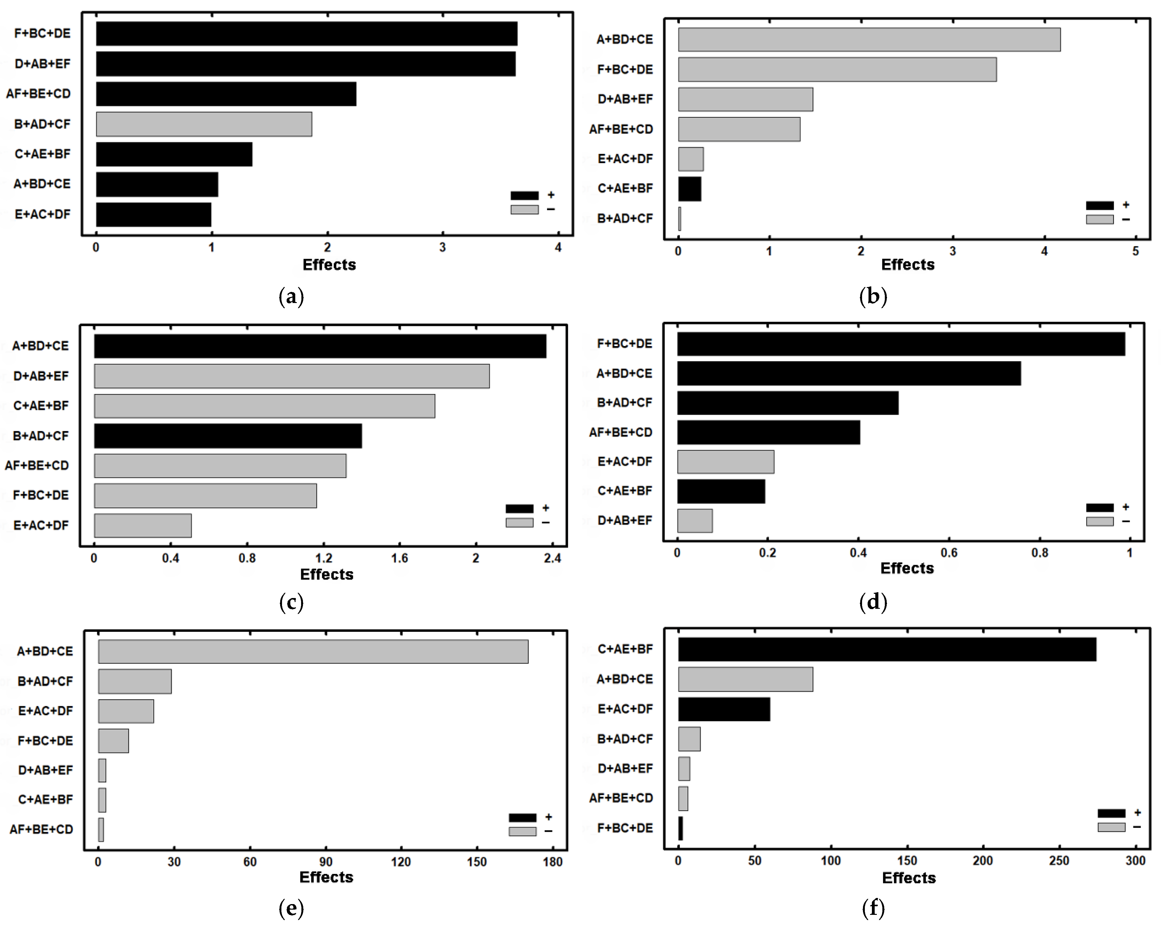
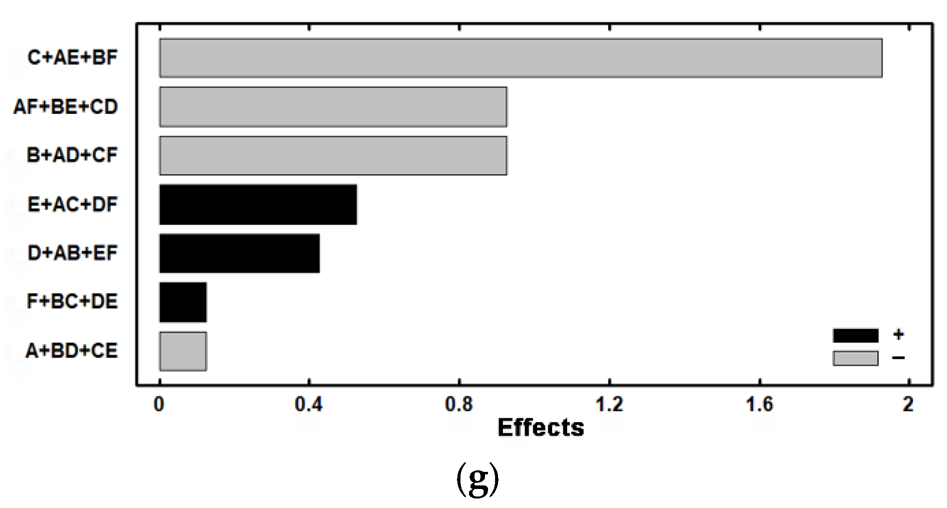
3. Results
4. Discussion
5. Conclusions
- The most effective destabilisation temperature would be 900 °C. At this temperature, a greater precipitation of secondary carbides is produced, thus raising the Ms temperature and favouring a reduction in retained austenite with values of less than 8% in weight. To complement this, if a double tempering of 4 h at 550 °C is carried out, this percentage falls to 3%.
- Nitriding significantly increases hardness, reaching values of 900 HV. This hardness is boosted if the destabilisation treatment is carried out at 1100 °C. This temperature is excessive for complete destabilisation of the austenite; therefore, the martensite formed during quenching presents greater hardness. At the same time, short tempering times maintain a certain tetragonality in the tempered martensite, thus favouring an increase in hardness.
- Resistance to wear increases notably with the nitriding treatment. To complement this, oil quenching and tempering times of 4 h are recommended. Resistance to wear increases with tempering at 500 °C for four hours. This favours the precipitation of nanometric MC carbides, associated with V.
Author Contributions
Funding
Institutional Review Board Statement
Informed Consent Statement
Data Availability Statement
Conflicts of Interest
References
- Huang, K.T.; Chang, S.H.; Chuang, C.Y. Microstructure and properties of composite produced by vacuum sintering of vanadis 4 extra steel powder with tantalum carbides and following heat treatment. Arch. Metall. Mater. 2020, 65, 555–563. [Google Scholar] [CrossRef]
- Talacchia, S.; Amador, J.; Urcola, J. High speed tool steel cut off dies made using powder metallurgy techniques. Rev. Metal. 1996, 32, 18–24. [Google Scholar] [CrossRef]
- Yan, F.; Shi, H.S.; Fan, J.F.; Xu, Z. An investigation of secondary carbides in the spray-formed high alloyed Vanadis 4 steel during tempering. Mater. Charact. 2008, 59, 883–889. [Google Scholar] [CrossRef]
- Nemec, M.; Jurci, P.; Kosnacova, P.; Kucerova, M. Evaluation of structural isotropy of Cr-V ledeburitic steel made by powder metallurgy of rapidly solidified particles. Kov. Mater.-Met. Mater. 2016, 54, 453–462. [Google Scholar] [CrossRef]
- Sobotova, J.; Jurci, P.; Adamek, J.; Salabova, P.; Prikner, O.; Sustarsic, B.; Jenko, D. Diagnostics of the microstructural changes in sub-zero-processed vanadis 6 p/m ledeburitic tool steel. Mater. Tehnol. 2013, 47, 93–98. [Google Scholar]
- Arslan, F.K.; Altinsoy, I.; Hatman, A.; Ipek, M.; Zeytin, S.; Bindal, C. Characterization of cryogenic heat treated Vanadis 4 PM cold work tool steel. Vacuum 2011, 86, 370–373. [Google Scholar] [CrossRef]
- Gunes, I.; Uzun, M.; Cetin, A.; Aslantas, K.; Cicek, A. Evaluation of wear performance of cryogenically treated Vanadis 4 Extra tool steel. Kov. Mater.-Met. Mater. 2016, 54, 195–204. [Google Scholar] [CrossRef]
- Chang, S.H.; Chuang, C.Y.; Huang, K.T. Mechanical Properties and Microstructures of Mo2C Strengthened Vanadis 4 Extra Alloy Steel by Powder Metallurgy and Heat Treatments. Isij Int. 2019, 59, 1354–1361. [Google Scholar] [CrossRef]
- Jurci, P.; Domankova, M.; Ptacinova, J.; Pasak, M.; Kusy, M.; Priknerova, P. Investigation of the Microstructural Changes and Hardness Variations of Sub-Zero Treated Cr-V Ledeburitic Tool Steel Due to the Tempering Treatment. J. Mater. Eng. Perform. 2018, 27, 1514–1529. [Google Scholar] [CrossRef]
- Pero-Sanz Elorz, J.A. Ciencia e Ingeniería de Materiales, 5th ed.; CIE DOSSAT 2000: Madrid, Spain, 2006; p. 673. [Google Scholar]
- Powell, G.L.F.; Bee, J.V. Secondary carbide precipitation in an 18 wt% Cr-1 wt% Mo white iron. J. Mater. Sci. 1996, 31, 707–711. [Google Scholar] [CrossRef]
- Gonzalez-Pocino, A.; Alvarez-Antolin, F.; Asensio-Lozano, J. Improvement of Adhesive Wear Behavior by Variable Heat Treatment of a Tool Steel for Sheet Metal Forming. Materials 2019, 12, 10. [Google Scholar] [CrossRef] [PubMed]
- Efremenko, V.; Shimizu, K.; Chabak, Y. Effect of Destabilizing Heat Treatment on Solid-State Phase Transformation in High-Chromium Cast Irons. Metall. Mater. Trans. a-Phys. Metall. Mater. Sci. 2013, 44A, 5434–5446. [Google Scholar] [CrossRef]
- Jurci, P.; Domankova, M.; Hudakova, M.; Ptacinova, J.; Pasak, M.; Palcek, P. Characterization of microstructure and tempering response of conventionally quenched, short- and long-time sub-zero treated PM Vanadis 6 ledeburitic tool steel. Mater. Charact. 2017, 134, 398–415. [Google Scholar] [CrossRef]
- Durica, J.; Ptacinova, J.; Hudakova, M.; Kusy, M.; Jurci, P. Microstructure and Hardness of Cold Work Vanadis 6 Steel after Subzero Treatment at-140 degrees C. Adv. Mater. Sci. Eng. 2018, 9, 1–7. [Google Scholar] [CrossRef]
- Gonzalez-Pocino, A.; Asensio-Lozano, J.; Alvarez-Antolin, F.; Garcia-Diez, A. Improvement of Impact Toughness and Abrasion Resistance of a 3C-25Cr-0.5Mo Alloy Using a Design of Experiment Statistical Technique: Microstructural Correlations after Heat Treatments. Metals 2021, 11, 595. [Google Scholar] [CrossRef]
- Pero-Sanz, J.A. Aceros; Dossat, Ed.; Dossat: Madrid, Spain, 2004; p. 558. [Google Scholar]
- Vilar, R.; Colaco, R.; Almeida, A. Laser surface treatment of tool steels. Laser Process. Surf. Treat. Film Depos. 1996, 307, 453–478. [Google Scholar]
- Hui, L.; Han-Guang, F.; Jiang, J.; Jun, W. Effect of heat treatment on microstructure and property of high vanadium wear-resistant alloy. Materialwissenschaft Und Werkstofftechnik 2018, 49, 1485–1493. [Google Scholar] [CrossRef]
- Selte, A.; Ozkal, B.; Arslan, K.; Ulker, S.; Hatman, A. Effect of Nitriding on the Wear Resistance of Tool Powder Steels with Different Contents of V, Cr and Mo. Metal Sci. Heat Treat. 2018, 59, 729–734. [Google Scholar] [CrossRef]
- Jurci, P. Saturation of the Cr-V ledeburitic steel with nitrogen. Kov. Mater.-Met. Mater. 2010, 48, 217–226. [Google Scholar] [CrossRef]
- Hosmani, S.S.; Schacherl, R.E.; Mittemeijer, E.J. Nitrogen uptake by an Fe-V alloy: Quantitative analysis of excess nitrogen. Acta Mater. 2006, 54, 2783–2792. [Google Scholar] [CrossRef]
- Diaz, N.E.V.; Schacherl, R.E.; Zagonel, L.F.; Mittemeijer, E.J. Influence of the microstructure on the residual stresses of nitrided iron-chromium alloys. Acta Mater. 2008, 56, 1196–1208. [Google Scholar] [CrossRef]
- Prat-Bartés, A.; Tort-Martorell, X.; Grima-Cintas, P.; Pozueta-Fernández, L.; Solé-Vidal, I. Métodos Estadísticos, 2nd ed.; UPC: Barcelona, Spain, 2004; p. 376. [Google Scholar]
- Gonzalez-Pocino, A.; Alvarez-Antolin, F.; Asensio-Lozano, J. Erosive Wear Resistance Regarding Different Destabilization Heat Treatments of Austenite in High Chromium White Cast Iron, Alloyed with Mo. Metals 2019, 9, 10. [Google Scholar] [CrossRef]
- Gonzalez-Pocino, A.; Alvarez-Antolin, F.; Asensio-Lozano, J. Influence of Thermal Parameters Related to Destabilization Treatments on Erosive Wear Resistance and Microstructural Variation of White Cast Iron Containing 18% Cr. Application of Design of Experiments and Rietveld Structural Analysis. Materials 2019, 12, 3252. [Google Scholar] [CrossRef] [PubMed]
- Gonzalez-Pocino, A.; Alvarez-Antolin, F.; Asensio-Lozano, J. Optimization of Quenching and Tempering Parameters for the Precipitation of M7C3 and MC Secondary Carbides and the Removal of the Austenite Retained in Vanadis 10 Tool Steel. Metals 2019, 9, 627. [Google Scholar] [CrossRef]


| C | Si | Mn | Cr | Mo | V |
|---|---|---|---|---|---|
| 1.4 | 0.4 | 0.5 | 4.7 | 3.5 | 3.7 |
| Factors | Levels | ||
|---|---|---|---|
| Code | Description of Factors | Level −1 | Level +1 |
| A | Destabilisation temperature (°C) | 1100 | 900 |
| B | Dwell time at destabilisation temperature (h) | 4 | 8 |
| C | Nitriding | No | Yes |
| D | Quench cooling medium | air | oil |
| E | Nº of temperings at 550 °C | 2 | 3 |
| F | Time of tempering (h) | 2 | 4 |
| No. | A | B | C | D | E | F | Restricted Confounding Pattern |
|---|---|---|---|---|---|---|---|
| 1 | −1 | −1 | −1 | +1 | +1 | +1 | A + BD + CE B + AD + CF C + AE + BF D + AB + EF E + AC + DF F + BC + DE AF + BE + CD |
| 2 | +1 | −1 | −1 | −1 | −1 | +1 | |
| 3 | −1 | +1 | −1 | −1 | +1 | −1 | |
| 4 | +1 | +1 | −1 | +1 | −1 | −1 | |
| 5 | −1 | −1 | +1 | +1 | −1 | −1 | |
| 6 | +1 | −1 | +1 | −1 | +1 | −1 | |
| 7 | −1 | +1 | +1 | −1 | −1 | +1 | |
| 8 | +1 | +1 | +1 | +1 | +1 | +1 |
| Gas Mixture | 70%N2 + 30%H2 |
|---|---|
| Gas flux (cm3/min) | 500 |
| Temperature (°C) | 540 |
| Pressure (Pa) | 400 |
| Time (min) | 120 |
| Output voltage (V) | 500 |
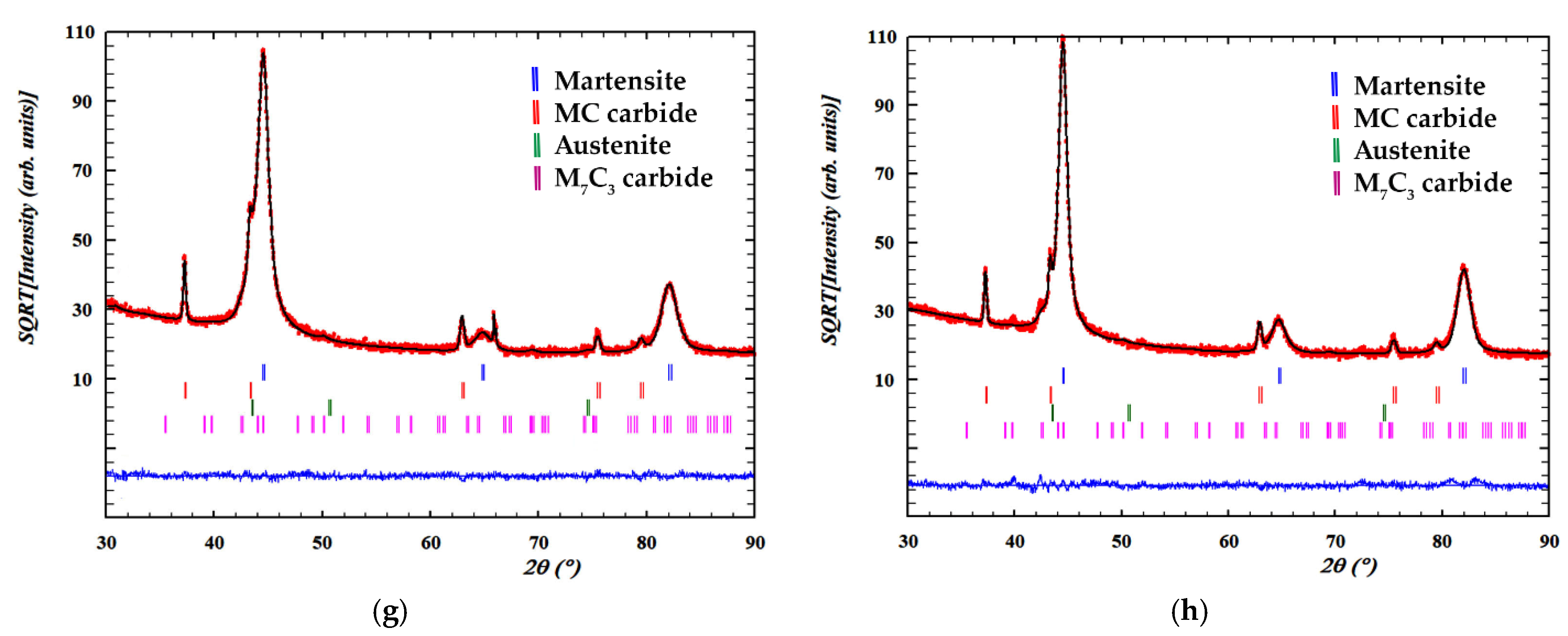
| Experiment | Martensite | Austenite | ||||||
| 2θ | I | 2θ | I | 2θ | I | 2θ | I | |
| 1 | 44.442 | 8907 | 64.710 | 109 | 81.994 | 399 | 43.676 | 1220 |
| 2 | 44.436 | 7901 | 64.613 | 192 | 81.936 | 600 | 43.778 | 722 |
| 3 | 44.426 | 8669 | 64.699 | 98 | 81.934 | 405 | 43.689 | 1489 |
| 4 | 44.408 | 7171 | 64.488 | 243 | 81.829 | 911 | 43.773 | 1093 |
| 5 | 44.427 | 10,189 | 64.761 | 120 | 82.025 | 405 | 43.850 | 1150 |
| 6 | 44.467 | 8350 | 64.550 | 192 | 81.911 | 524 | 43.802 | 1313 |
| 7 | 44.516 | 7158 | 64.816 | 101 | 82.049 | 403 | 43.824 | 425 |
| 8 | 44.456 | 8152 | 64.640 | 210 | 81.950 | 584 | 43.681 | 332 |
| Experiment | MC carbides | |||||||
| 2θ | I | 2θ | I | 2θ | I | 2θ | I | |
| 1 | 37.213 | 1246 | 62.858 | 203 | 75.396 | 111 | 79.454 | 41 |
| 2 | 37.208 | 1122 | 62.833 | 194 | 75.373 | 113 | 79.306 | 26 |
| 3 | 37.176 | 1391 | 62.797 | 222 | 75.336 | 127 | 79.290 | 32 |
| 4 | 37.180 | 786 | 62.777 | 213 | 75.296 | 128 | 79.248 | 37 |
| 5 | 37.206 | 1122 | 43.393 | 2297 | 75.415 | 107 | 79.425 | 23 |
| 6 | 37.249 | 877 | 62.830 | 159 | 75.349 | 96 | 79.179 | 26 |
| 7 | 37.262 | 1329 | 62.892 | 236 | 75.435 | 123 | 79.484 | 34 |
| 8 | 37.214 | 988 | 62.841 | 184 | 75.377 | 98 | 79.325 | 37 |
| Experiment | M7C3 carbides | |||||||
| 2θ | I | |||||||
| 1 | 43.037 | 361 | ||||||
| 2 | 42.377 | 236 | ||||||
| 3 | 42.380 | 148 | ||||||
| 4 | 42.376 | 134 | ||||||
| 5 | 42.423 | 141 | ||||||
| 6 | 42.531 | 186 | ||||||
| 7 | 42.481 | 144 | ||||||
| 8 | 42.362 | 180 | ||||||
| No. | Rietveld Fitting | Phases | a (Å) | c (Å) | wt. % | Vol. (Å3) |
|---|---|---|---|---|---|---|
| 1 | Rwp = 7.73 Rexp = 5.95 Chi2 = 1.69 | Martensite | 2.87514 | 79.46 ± 1.98 | 23.767 ± 0.004 | |
| Austenite | 3.60122 | 6.78 ± 0.64 | 46.704 ± 0.014 | |||
| M7C3 | 7.04759 | 4.53305 | 9.40 ± 1.71 | 194.986 ± 0.73 | ||
| MC | 4.17342 | 4.36 ± 0.55 | 72.690 ± 0.016 | |||
| 2 | Rwp = 10.1 Rexp = 6.99 Chi2 = 2.09 | Martensite | 2.87696 | 78.14 ± 2.26 | 23.812 ± 0.003 | |
| Austenite | 3.60122 | 3.02 ± 0.68 | 46.704 ± 0.014 | |||
| M7C3 | 7.04759 | 4.53305 | 13.02 ± 2.10 | 194.986 ± 0.73 | ||
| MC | 4.17785 | 5.81 ± 0.70 | 72.817 ± 0.015 | |||
| 3 | Rwp = 7.52 Rexp = 5.79 Chi2 = 1.68 | Martensite | 2.87675 | 72.58 ± 1.90 | 23.807 ± 0.004 | |
| Austenite | 3.60122 | 10.37 ± 0.72 | 46.704 ± 0.014 | |||
| M7C3 | 7.04759 | 4.53305 | 12.71 ± 1.88 | 194.986 ± 0.73 | ||
| MC | 4.17789 | 4.34 ± 0.54 | 72.924 ± 0.014 | |||
| 4 | Rwp = 9.42 Rexp = 6.68 Chi2 = 1.99 | Martensite | 2.88094 | 74.02 ± 2.17 | 23.911 ± 0.004 | |
| Austenite | 3.60122 | 6.33 ± 0.73 | 46.704 ± 0.014 | |||
| M7C3 | 7.04759 | 4.53305 | 14.83 ± 2.17 | 194.986 ± 0.73 | ||
| MC | 4.18092 | 4.83 ± 0.66 | 73.083 ± 0.019 | |||
| 5 | Rwp = 8.23 Rexp = 5.43 Chi2 = 2.3 | Martensite | 2.87462 | 78.42 ± 1.83 | 23.754 ± 0.004 | |
| Austenite | 3.60122 | 9.44 ± 0.65 | 46.704 ± 0.014 | |||
| M7C3 | 7.04759 | 4.53305 | 7.97 ± 1.53 | 194.986 ± 0.73 | ||
| MC | 4.17055 | 4.18 ± 0.55 | 72.541 ± 0.015 | |||
| 6 | Rwp = 8.87 Rexp = 6.68 Chi2 = 1.76 | Martensite | 2.88061 | 74.60 ± 2.23 | 23.903 ± 0.004 | |
| Austenite | 3.60122 | 7.79 ± 0.77 | 46.704 ± 0.014 | |||
| M7C3 | 7.04759 | 4.53305 | 13.21 ± 2.18 | 194.986 ± 0.73 | ||
| MC | 4.18027 | 4.40 ± 0.69 | 73.049 ± 0.018 | |||
| 7 | Rwp = 8.62 Rexp = 6.18 Chi2 = 1.94 | Martensite | 2.87563 | 74.33 ± 2.06 | 23.779 ± 0.003 | |
| Austenite | 3.60122 | 8.74 ± 0.73 | 46.704 ± 0.014 | |||
| M7C3 | 7.04759 | 4.53305 | 11.59 ± 1.97 | 194.986 ± 0.73 | ||
| MC | 4.17578 | 5.33 ± 0.65 | 72.814 ± 0.011 | |||
| 8 | Rwp = 9.96 Rexp = 7.01 Chi2 = 2.02 | Martensite | 2.87724 | 82.24 ± 2.36 | 23.819 ± 0.004 | |
| Austenite | 3.60122 | 1.50 ± 0.67 | 46.704 ± 0.014 | |||
| M7C3 | 7.04759 | 4.53305 | 10.06 ± 2.02 | 194.986 ± 0.73 | ||
| MC | 4.17644 | 6.20 ± 0.75 | 72.848 ± 0.017 |
| Experiment | Ferrite | Austenite | Effect | ||
| (wt.%) | Effect | (wt.%) | Effect | ||
| 1 | 79.46 | 76.723 | 6.78 | 6.746 | Average |
| 2 | 78.14 | 1.052 | 3.02 | −4.172 | A + BC + CE |
| 3 | 72.58 | −1.862 | 10.37 | −0.022 | B + AD + CF |
| 4 | 74.02 | 1.347 | 6.33 | 0.242 | C + AE + BF |
| 5 | 78.42 | 3.622 | 9.44 | −1.467 | D + AB + EF |
| 6 | 74.6 | 0.992 | 7.79 | −0.272 | E + AC + DF |
| 7 | 74.33 | 3.637 | 8.74 | −3.472 | F + BC + DE |
| 8 | 82.24 | 2.242 | 1.50 | −1.327 | AF + BE + CD |
| Experiment | Cr7C3 | VC | Effect | ||
| (wt.%) | Effect | (wt.%) | Effect | ||
| 1 | 9.40 | 11.598 | 4.36 | 4.931 | Average |
| 2 | 13.02 | 2.362 | 5.81 | 0.757 | A + BC + CE |
| 3 | 12.71 | 1.397 | 4.34 | 0.487 | B + AD + CF |
| 4 | 14.83 | −1.782 | 4.83 | 0.192 | C + AE + BF |
| 5 | 7.97 | −2.067 | 4.18 | −0.077 | D + AB + EF |
| 6 | 13.21 | −0.507 | 4.40 | −0.212 | E + AC + DF |
| 7 | 11.59 | −1.162 | 5.33 | 0.987 | F + BC + DE |
| 8 | 10.06 | −1.317 | 6.20 | 0.402 | AF + BE + CD |
| Experiment | Before Nitriding | After Nitriding | Effect | ||
| HV (300 N) | Effect | HV (300 N/0.5 N) | Effect | ||
| 1 | 732 | 648.5 | 732 | 786.9 | Average |
| 2 | 585 | −170.0 | 585 | −88.2 | A + BC + CE |
| 3 | 716 | −29.0 | 716 | −14.2 | B + AD + CF |
| 4 | 567 | −3.0 | 567 | 273.7 | C + AE + BF |
| 5 | 761 | −3.0 | 937 1 | −7.2 | D + AB + EF |
| 6 | 574 | −22.0 | 922 1 | 59.7 | E + AC + DF |
| 7 | 725 | −12.0 | 939 1 | 2.7 | F + BC + DE |
| 8 | 528 | −2.0 | 897 1 | −6.2 | AF + BE + CD |
| Experiment | Wear (Pin on Disk Test) | Effect | |||
| mg | Effect | ||||
| 1 | 4.2 | 1.7 | Average | ||
| 2 | 2.2 | −0.1 | A + BC + CE | ||
| 3 | 1.8 | −0.9 | B + AD + CF | ||
| 4 | 2.5 | −1.9 | C + AE + BF | ||
| 5 | 0.7 | 0.4 | D + AB + EF | ||
| 6 | 1.6 | 0.5 | E + AC + DF | ||
| 7 | 0.4 | 0.1 | F + BC + DE | ||
| 8 | 0.3 | −0.9 | AF + BE + CD | ||
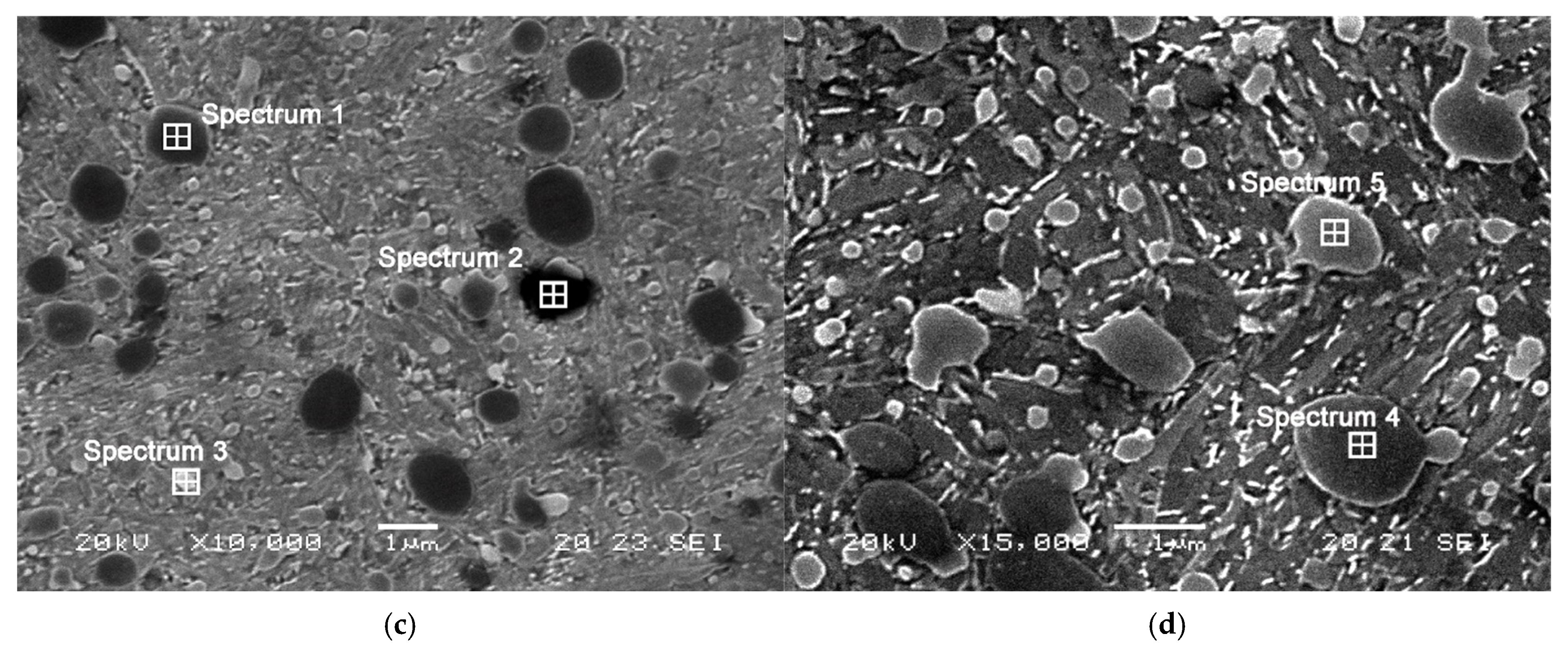
| Spectrum | %V | %Cr | %Fe | %Mo | Mixed Carbide |
|---|---|---|---|---|---|
| 1 | 20.67 | 2.89 | 25.84 | 4.44 | MC |
| 2 | 10.62 | 4.23 | 35.27 | 16.81 | M2C |
| 3 | 0.91 | 4.74 | 61.94 | 1.25 | M7C3 |
| 4 | 16.84 | 4.31 | 30.62 | 4.38 | MC |
| 5 | 0.75 | 5.51 | 63.11 | 0.94 | M7C3 |
| A(↓) × C(→) | −1 | +1 | D(↓) × F(→) | −1 | +1 |
|---|---|---|---|---|---|
| −1 | 724 | 938 | −1 | 819 | 762 |
| +1 | 576 | 909 | +1 | 752 | 814 |
| A(↓) × D(→) | −1 | +1 | C(↓) × F(→) | −1 | +1 |
|---|---|---|---|---|---|
| −1 | 1.1 | 2.4 | −1 | 2.15 | 3.2 |
| +1 | 1.9 | 1.4 | +1 | 1.15 | 0.3 |
| A(↓) × F(→) | −1 | +1 | B(↓) × E(→) | −1 | +1 | C(↓) × D(→) | −1 | +1 |
|---|---|---|---|---|---|---|---|---|
| −1 | 1.2 | 2.3 | −1 | 1.4 | 2.9 | −1 | 2.0 | 3.3 |
| +1 | 2.0 | 1.2 | +1 | 1.4 | 1.0 | +1 | 1.0 | 0.5 |
Publisher’s Note: MDPI stays neutral with regard to jurisdictional claims in published maps and institutional affiliations. |
© 2022 by the authors. Licensee MDPI, Basel, Switzerland. This article is an open access article distributed under the terms and conditions of the Creative Commons Attribution (CC BY) license (https://creativecommons.org/licenses/by/4.0/).
Share and Cite
Alvarez-Antolin, F.; Gonzalez-Pociño, A.; Cofiño-Villar, A.; Alvarez-Perez, C.H. Optimisation of Thermal Processes with Plasma Nitriding on Vanadis 4 High Speed Steel. Materials 2022, 15, 906. https://doi.org/10.3390/ma15030906
Alvarez-Antolin F, Gonzalez-Pociño A, Cofiño-Villar A, Alvarez-Perez CH. Optimisation of Thermal Processes with Plasma Nitriding on Vanadis 4 High Speed Steel. Materials. 2022; 15(3):906. https://doi.org/10.3390/ma15030906
Chicago/Turabian StyleAlvarez-Antolin, Florentino, Alejandro Gonzalez-Pociño, Alberto Cofiño-Villar, and Carlos Hugo Alvarez-Perez. 2022. "Optimisation of Thermal Processes with Plasma Nitriding on Vanadis 4 High Speed Steel" Materials 15, no. 3: 906. https://doi.org/10.3390/ma15030906
APA StyleAlvarez-Antolin, F., Gonzalez-Pociño, A., Cofiño-Villar, A., & Alvarez-Perez, C. H. (2022). Optimisation of Thermal Processes with Plasma Nitriding on Vanadis 4 High Speed Steel. Materials, 15(3), 906. https://doi.org/10.3390/ma15030906