Article

Corrosion Behavior of Candidate Functional Materials for Molten Salts Reactors in LiF–NaF–KF Containing Actinide Fluoride Imitators

The Institute of High Temperature Electrochemistry of the Ural Branch of the Russian Academy of Sciences, St. Akademicheskaya 20, 620066 Ekatherinburg, Russia
*
Author to whom correspondence should be addressed.
Materials 2022, 15(3), 761; https://doi.org/10.3390/ma15030761
Submission received: 10 November 2021 / Revised: 8 January 2022 / Accepted: 13 January 2022 / Published: 20 January 2022
(This article belongs to the Special Issue Electrochemical Energy Materials)

Abstract

:
Molten fluorides of alkali metals are considered a technological medium for molten salt reactors (MSRs). However, these media are known to be extremely corrosive. The successful implementation of high-temperature technological devices using molten alkali metal fluorides requires the selection of such structural materials that have high corrosion resistance in melts with compositional characteristic of MSRs. In this research, the corrosion behavior of 12Cr18Ni10Ti steel, the alloy Ni60Cr20Mo15, and the alloy Monel 404 (Ni50Cu50) was investigated in the LiF–NaF–KF eutectic melt, containing additions of CeF3 and NdF3 from 0 to 5 wt.% as imitator fluorides of actinides in an inert argon atmosphere at 550 °C for 100 h. Gravimetry, energy-dispersive X-ray (EDX) microanalysis of surfaces and cross-section of samples, and ICP-MS were used to establish the corrosion behavior of the investigated alloys. Corrosion resistance of the studied materials was found to decrease in a row from Monel 404 > Hastelloy C2000 > 12Cr18Ni10Ti. The addition of cerium fluoride into the melt resulted in the additional etching of the alloy surface. The addition of neodymium fluoride resulted in the formation of the point/inter-crystalline corrosion damages in the sample bulk. The samples of steel 12Cr18Ni10Ti were subjected to local cracking corrosion. The austenitic nickel-based alloys suffered specific local corrosion with formation of subsurface voids. Excellent corrosion resistance of the Monel alloy under the test conditions was found.

1. Introduction

Molten alkali metal halogenides are promising coolants, allowing for the expansion of the operating temperature range of power plants by hundreds of degrees, including nuclear reactors, to ensure efficient heat transfer from the hot zones of high-temperature devices.
Due to the thermal and radiation resistance in the temperature range from the melting point to the boiling point, halogenides compare favorably with water and organic heat carriers. In emergency situations, for example, in the case of damage or destruction to the pipeline or to the housing of the heat transfer device, they do not form explosive gas mixtures when interacting with water or a humid atmosphere. These properties, as well as basic thermophysical characteristics, make molten fluorides and chlorides of alkali metals attractive and competitive coolants, components of fuel mixtures, and regenerative media of new-generation nuclear reactors. The design of many high-temperature technological processes using molten salts, including newly developed ones, is associated with significant material science difficulties.
The significant aggressive action of alkali metal halide melts requires selection of resistant materials, development of methods of corrosion protection in molten salts, a detailed study of corrosion behavior, and the mechanism of destruction of materials.
Properties of molten fluoride salts enable their usage in molten salt reactors (MSRs) as solvents [1,2,3]. However, the successful usage of molten alkali fluorides [4,5,6,7] requires the development of functional materials having high corrosion resistance in the melt of composition characteristics for molten salts reactors. To date, this essential problem has not been solved [8,9,10]. The experimental data on metallic materials corrosion in molten salts are limited to the corrosion characteristics necessary for the analysis; apart from that, the standards of the experimental conditions are not sufficient or unavailable [11].
Molten salt reactor systems of the IV generation provide efficient fuel usage and cause minimal radioactive waste accumulation at safe and ecologically friendly operation [12]. High temperatures and concentrations of aggressive substances as well as significant rates of the interaction between metallic candidate material and electrolytes are of great concern both from economic and ecological safety perspectives for the molten salt industry [13]. The mechanism of corrosion in molten salts is fundamentally different from that in aqueous media, because the formation of the passive oxide layer on corrosion-resistant alloys becomes thermodynamically impossible [14,15], which limits usage of many known corrosion-resistant alloys [16,17].
Corrosion in the molten salt environment of reactors is associated with several factors including both thermodynamic and kinetic aspects, the formation of fluorides of functional material components as a result of interaction with the medium, and the influence of impurities containing oxygen and water as well as the fission products of spent nuclear fuel (SNF). The majority of functional candidate materials are damaged by selective chromium dissolution in the fluoride formed from the alloy in the electrolyte [18,19,20,21,22]. Moisture and oxides being typical impurities that alongside with the temperature gradient and electrochemical potential difference between various metals are considered to be the corrosion driving forces. Apart from them, doping elements of functional materials dissolved in molten salts boost their corrosion [23].
Currently, nickel-based alloys are considered to be the most promising and, consequently, the most precisely studied corrosion-resistant candidate functional materials. Aluminum is known to be more susceptible to dissolution than other components of the functional materials, and the corrosion of doping components increases from nickel and cobalt to iron, chromium, and aluminum. However, the available literature data are miscellaneous and sometimes contradictory, which is explained by the obvious experimental difficulties including the quality of the salt preparation, purity of the atmosphere over the melt, among others. It is known that plutonium and americium fluorides are imitated by cerium and neodymium fluorides [24,25,26,27,28,29]. It is reasonable first to analyze lanthanide fluorides, as the elements are similar to actinide fluorides’ physical–chemical, thermodynamic, and other properties, and then inquire into the study of individual actinide fluorides and their mixtures. MSR engineering depends greatly on the successful selection and development of the corresponding functional materials. Selection of the alloy with the ideal composition is nearly impossible, because other corrosion-preventive methods are required apart from the material doping.
We have previously studied the corrosion behavior of a number of metallic materials, including iron and nickel austenites of different element and mass compositions of alloys, during short-term corrosion tests. It was found that 12Cr18Ni10Ti and Hastelloy C2000 might be the most appropriate candidate materials for further study as MSR container materials due to the fact of their availability, low cost, and a relatively low corrosion activity in the studied aggressive media. Monel 404 has also demonstrated excellent corrosion resistance in similar temperature conditions [30].
The present paper focused on the study of the corrosion behavior [31,32,33,34,35,36,37,38,39,40,41,42,43,44,45,46,47,48,49] of the FeCrNiTi, NiCrMo, and NiCu alloys during long-term corrosion tests in the high-temperature aggressive alkali fluorides containing cerium trifluoride and neodymium trifluoride as imitators of the nuclear fuel fission products (uranium and plutonium fluorides).

2. Materials and Methods

2.1. Materials

In this work, the corrosion behavior of steel 12Cr18Ni10Ti steel and Hastelloy C2000 (Ni60Cr20Mo15) and Monel 404 (Ni50Cu50) alloys was investigated. Before testing, the alloys were certified for compliance with the actual composition of the declared one, cut into specimens of a given size convenient for testing, ground, polished successively with abrasive paper of various grain sizes, degreased in an alcohol–acetone mixture, and dried in an oven. The original grade compositions of the materials are presented in Table 1.
To determine the conformity of the real composition of the studied alloys and their declared composition, metallographic analyses was carried out using a microscope GEOL SM-5900 L. Samples of corrosion-resistant austenitic steel based on iron 12Cr18Ni10Ti were plated rounded on one side in the form of a semicircular segment with a length of 8.56–9.35 mm, width from 6.65 to 6.67, and a thickness from 1.32 to 1.41 mm. The metallographic analyses of the samples of the studied steel is shown in Figure 1.
Samples of the Hastelloy C-2000 high nickel alloy consisted of elongated square bars with a length of 6.0–8.13 mm, a width of 2.5–3.08 mm, and a thickness of 2.5–3.0 mm. Metallographic analyses of the Hastelloy C-2000 samples are shown in Figure 2.
Samples of the nickel–copper alloy “Monel 404” were square bars with a length of 6.05–6.12 mm, a width of 6.21–6.24 mm, and a thickness of 5.98 mm. Metallographic analyses of the Monel 404 samples are shown in Figure 3.
According to the results of the metallographic analyses data, the studied metals corresponded to the declared ones.
To prepare the FLiNaK eutectic mixture (46.5 LiF–11.5 NaF–42 KF, mol.%), the following individual salts were used:
  • − Lithium fluoride LiF of “extra” qualification, mass fraction of LiF: 99.0%;
  • − Sodium fluoride NaF of analytical grade, mass fraction of NaF: 99.0%;
  • − Acidic potassium fluoride KHF2, analytical grade, mass fraction KHF2: 99–101%.
A feature of the developed technique for preparing the FLiNaK eutectic mixture was that instead of the hygroscopic component KF, its acidic anhydrous salt KHF2 was used. The melting point of KHF2 is 238.7 °C, and the boiling point is in the range 400–500 °C. The decomposition reaction of KHF2 takes place already at temperatures of 300–400 °C:
KHF 2   KF + HF
Thus, the introduction of the KHF2 component leads not only to the production of anhydrous KF in the FLiNaK eutectic mixture, but also to additional fluorination of impurities. The reactions of formation of volatile compounds of oxygen, sulfur, and phosphorus, which are removed from the melt, can be written as follows:
O 2 + 2 HF   H 2 O ( g ) + 2 F
S 2 + 2 HF   H 2 S ( g ) + 2 F ;
P 3 + 3 HF   PH 3 ( g ) + 3 F
A crucible from glassy carbon with weighed portions of individual components was placed in a resistance furnace. Heating was carried out at a rate of about 2.5 °C/min to a temperature of 750 °C for 5–6 h. At this temperature, the melt was kept for 2 h. Then, the melt was cooled and transferred to a box with a controlled atmosphere (humidity not more than 2 ppm, oxygen content 2–9 ppm). The prepared melt was stored in a box in a glass container with a tightly closed lid.

2.2. Methods

A series of corrosion experiments were performed at 550 °C, the materials were exposed for 100 h in molten alkali fluorides with up to 5 wt.% additions of cerium and neodymium fluorides. All tests were performed in an inert argon glove box atmosphere with the humidity not more than 2 ppm and oxygen concentration not more than 10 ppm.
A specially developed high-temperature experimental bench containing isolated metallic tubes provided physical separation of the working areas of separate parallel experiments, which is required for operation with molten alkali halide melts. Such construction enabled parallel corrosion tests of the samples in the working space of one furnace. In addition, this bench allowed for sampling of the melt during the experiment. The samples of salts’ electrolytes were taken every 8 h to monitor the changes in the composition of corrosion products in the melt.
Five samples of the studied materials were tested in a parallel to increase the data reliability.
To perform a gravimetric analysis, the size of the samples was measured before and after the test. These data were used to calculate the contact area of the materials with the molten salt electrolyte using a digital vernier caliper. The samples were weighted multiple times using an analytical balance MSA 225P (Fisher Scientific, Waltham, MA, USA) with an accuracy of ±0.00001 g.
After the experiments, the samples were rinsed from the remaining fluoride salts in hot boric acid (5 wt.%) solution in the thermostate under continuous stirring at 80 °C for 90 min. Such rinsing fluid has an optimal composition and concentration considering the temperature dependence of the fluoride solubility, which allows for eliminating additional corrosion effects on the materials that were in contact with molten fluorides.
The grade compositions of the studied materials were primarily proved by energy-dispersive X-ray (EDX) microanalysis. The concentration of impurities was characterized using an inductively coupled plasma mass-spectrometer NexIon 2000 (Perkin Elmer, Waltham, MA, USA) and an oxygen/nitrogen/hydrogen elemental analyzer OH836 (Leco Corporation, Joseph, MI, USA).
The changes in the surface morphology and cross-section of the samples were recorded by EDX microanalysis using a JEOL JSM-5900 LV scanning electron microscope (JEOL, Tokyo, Japan).
The solidified melts after the corrosion test, electrolyte probes, and rinsing fluids were subjected to the elemental analysis using a NexION 2000 mass spectrometer (Perkin Elmer, Waltham, MA, USA). When calculating the corrosion rate using gravimetric analysis, the amount of salt remaining in the samples was determined at several points on the sample’s surface using EDX microanalysis, and the value was recalculated for the average surface area to update the real change in the sample’s mass.

3. Results and Discussion
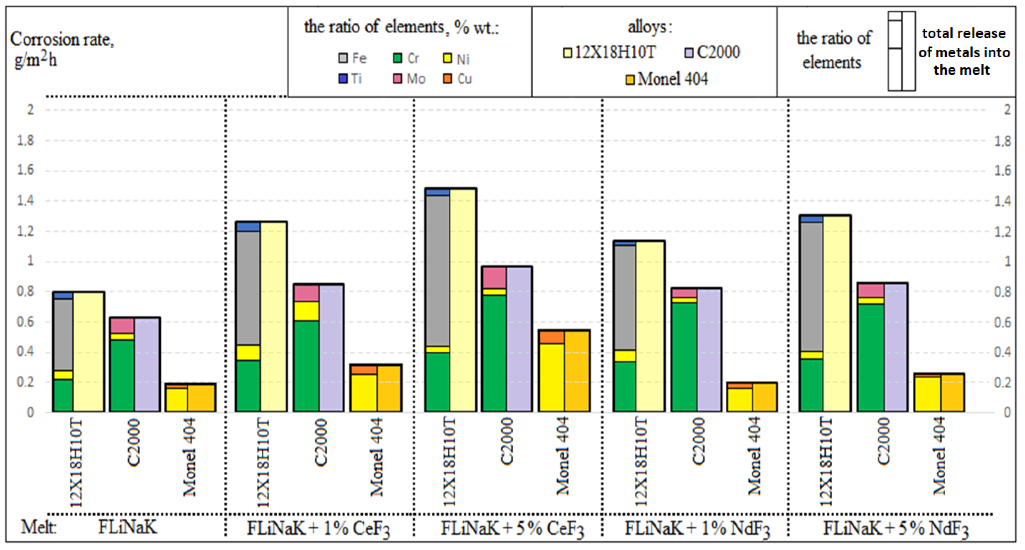
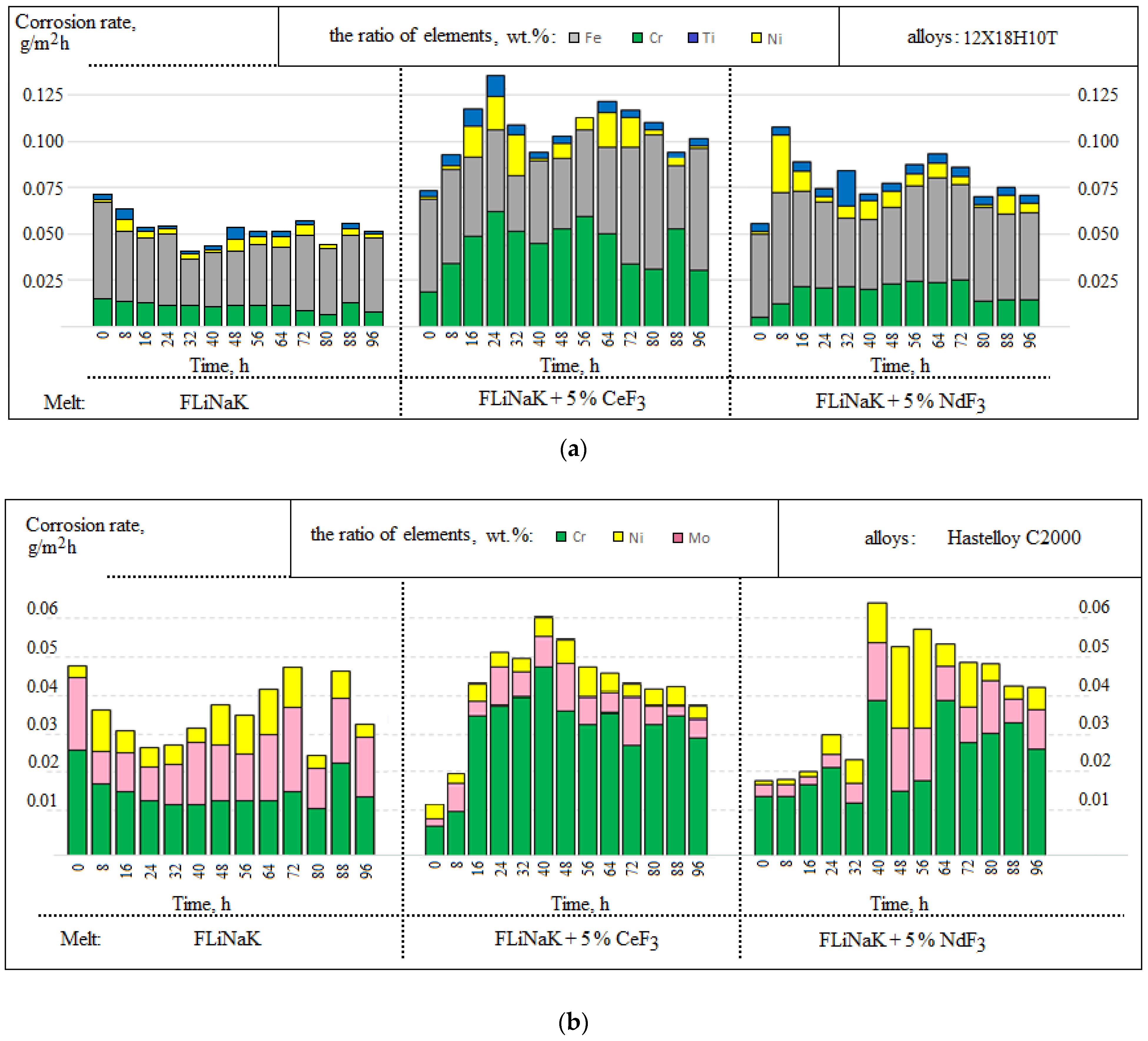
3.1. Corrosion Rate

Table 2 illustrates the rates of the candidate materials’ corrosion calculated according to gravimetric analysis with the updated real sample mass variation determined by the EDX microanalysis of the unextracted salt in some point for 12Cr18Ni10Ti, Monel 404, and Hastelloy C2000 depending on the electrolyte composition. These samples were preliminary exposed for 100 h in the fluoride melt at 550 °C.
The samples of the 12Cr18Ni10Ti steel demonstrated the largest corrosion rate, on average 1.5 times greater than those of the Hastelloy C2000 alloy and more than five times greater than those of the Monel 404 alloy. As the concentration of cerium and neodymium in fluoride melts increased, the materials’ corrosion rate also increased. Conversely, the addition of cerium fluoride into the melt led to a greater corrosion effect than the addition of neodymium fluoride.
Figure 4 shows the corrosion rates according to the chemical analysis of the melts after the experiments with samples of Monel 404, Hastelloy C2000, and steel 12Cr18Ni10Ti depending on the experimental conditions.
The rates of corrosion, calculated according to the chemical analysis of the molten salts obtained after interacting with the metallic samples, correlated with the values of the corrosion rates obtained by the modified gravimetric analysis. Considering these data, we concluded that the greater the concentration of cerium and neodymium fluorides, the greater the degradation processes in the materials.
A selective dissolution of chromium and titanium was observed in the 12Cr18Ni10Ti steel alongside an active iron transition to the melt. Considering the Hastelloy C2000 alloy, for the most part, chromium transferred to the electrolyte, whereas the nickel concentration was negligible in the frozen probes of the molten salt. The Monel 404 alloy was characterized mainly by the nickel dissolution; the addition of cerium fluoride slightly increased a copper transition to the melt.
Figure 5 illustrates the kinetic characteristics of the transfer of the initial melt components to the salt phase during the corrosion exposure in the alkali metals’ fluorides; the data are presented according to the analysis of the melt samples taken every 8 h.
According to the chemical analysis of the samples, there was a significant increase in the dissolvable Hastelloy C2000, Monel 404, and 12Cr18Ni10Ti components into the electrolyte after 16 h of exposure when cerium and neodymium fluorides were added into the electrolyte. In addition, during the experiments in the FLiNaK melt, a parabolic time dependence of corrosion was recorded. Such behavior may be related to the processes in the subsurface material volume, i.e., the denuding of the inner subsurface layers caused by the dissolution of surface layers during the corrosion tests. Such behavior intermittently increases the total corrosion rate. The corrosion charter was qualified as localized and subsurface.
Apart from that, the Hastelloy C2000 alloy illustrated high selectivity of the molybdenum transfer into the melt, which was not determined by the chemical analysis of the resulting melt (Figure 5b). This may be related with the formation of volatile molybdenum–fluorine compounds of various oxidation degrees at a long-term contact of the material with the corrosive environment during the experiment and their subsequent evacuation from the system. This explains the insignificant deviation in the data of the corrosion rates obtained by the gravimetric and chemical analyses.

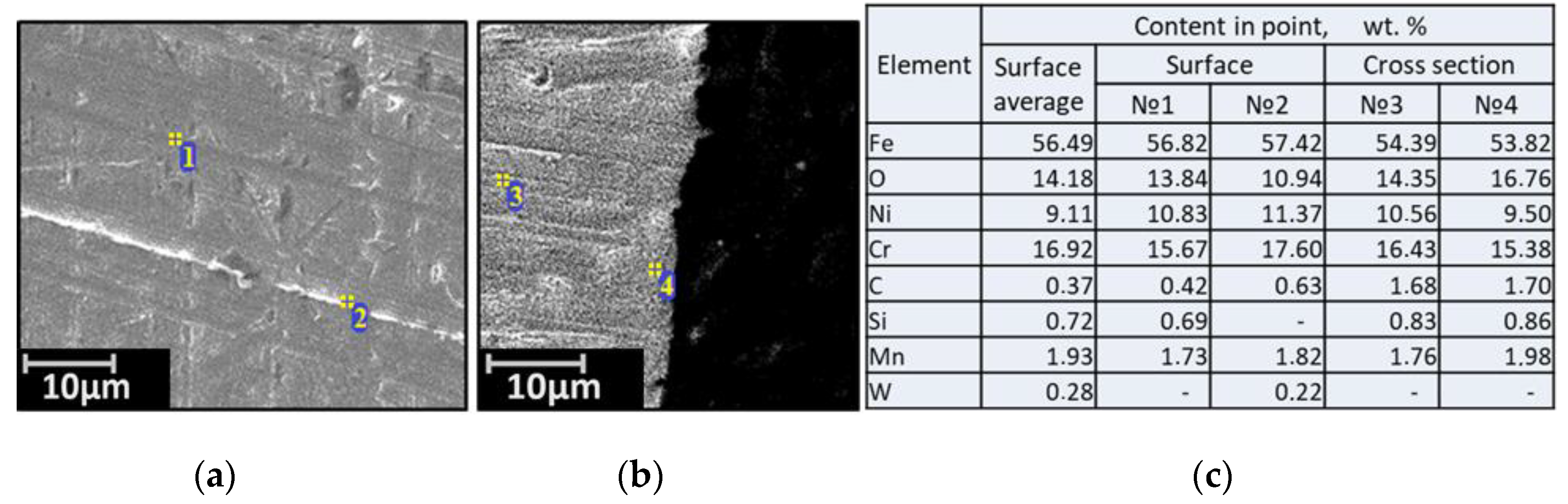
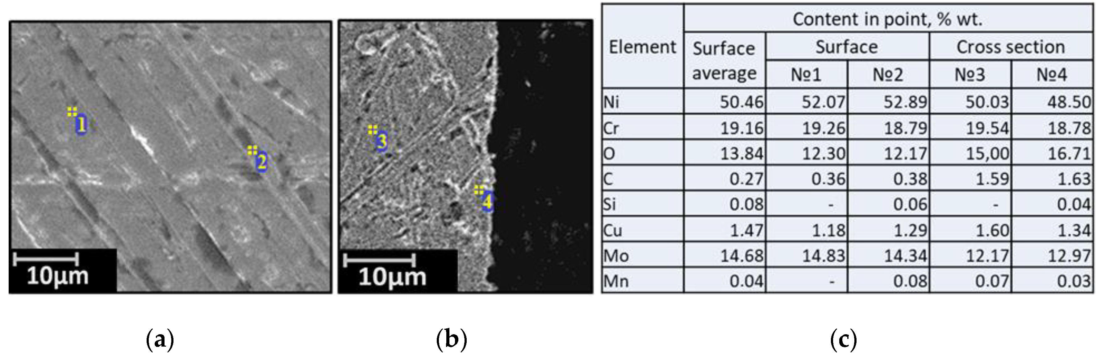
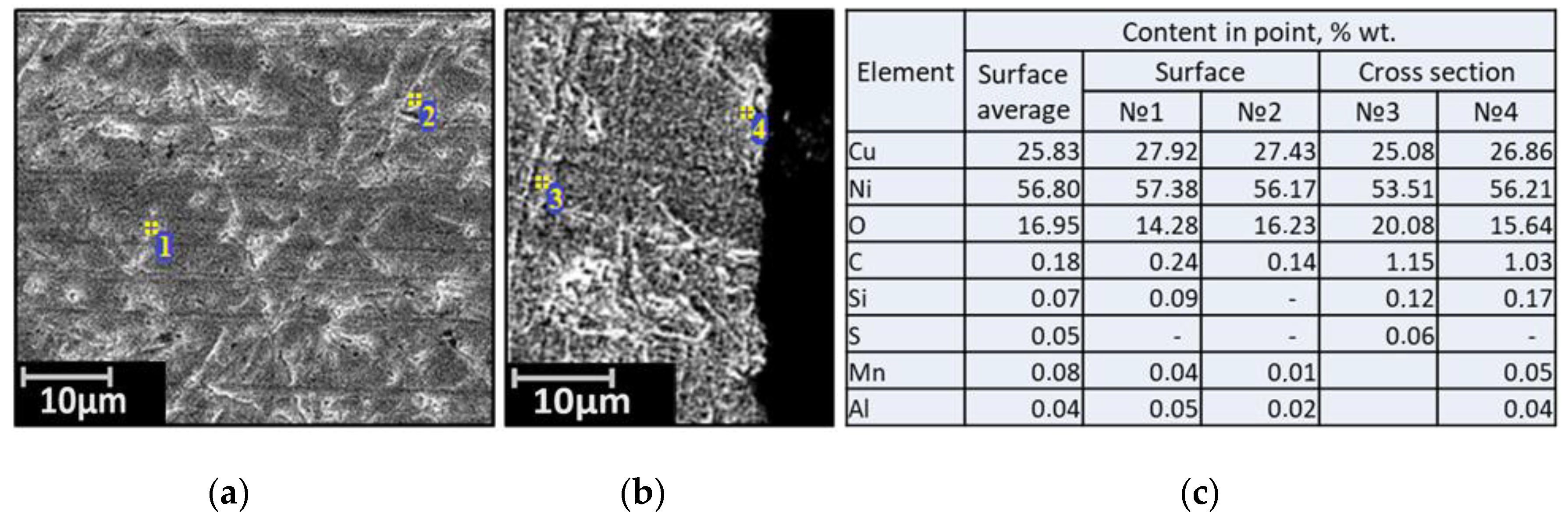
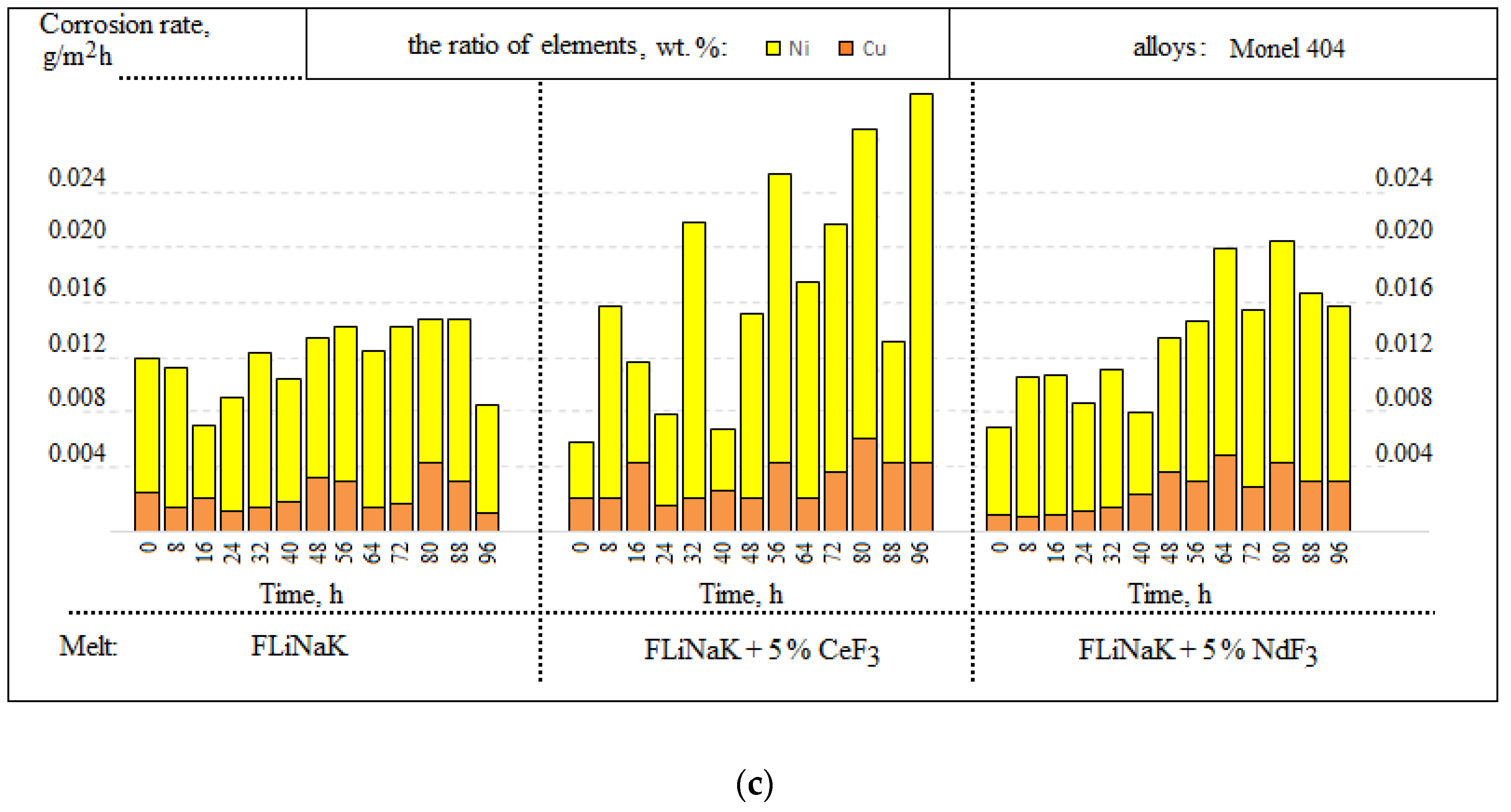
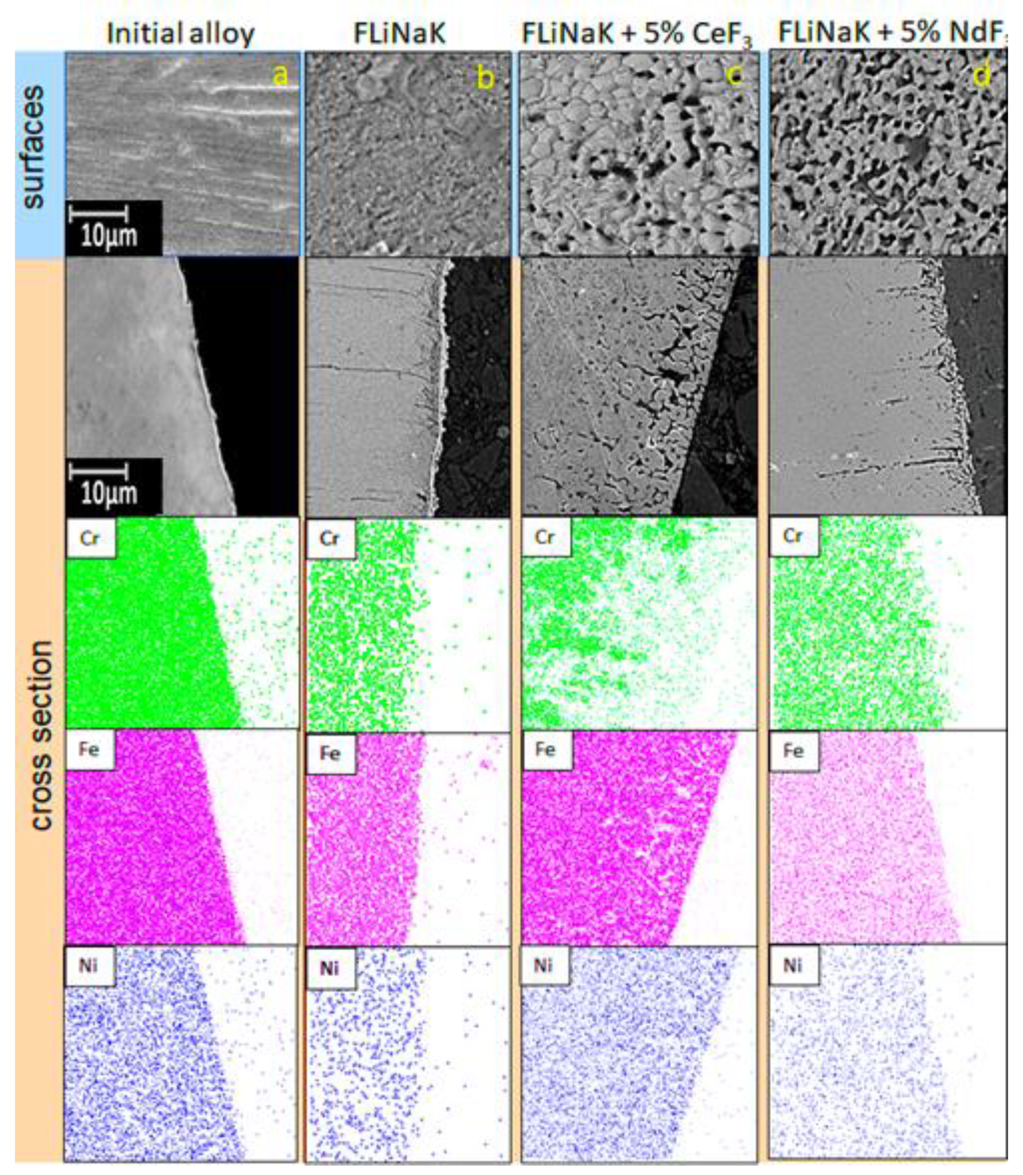
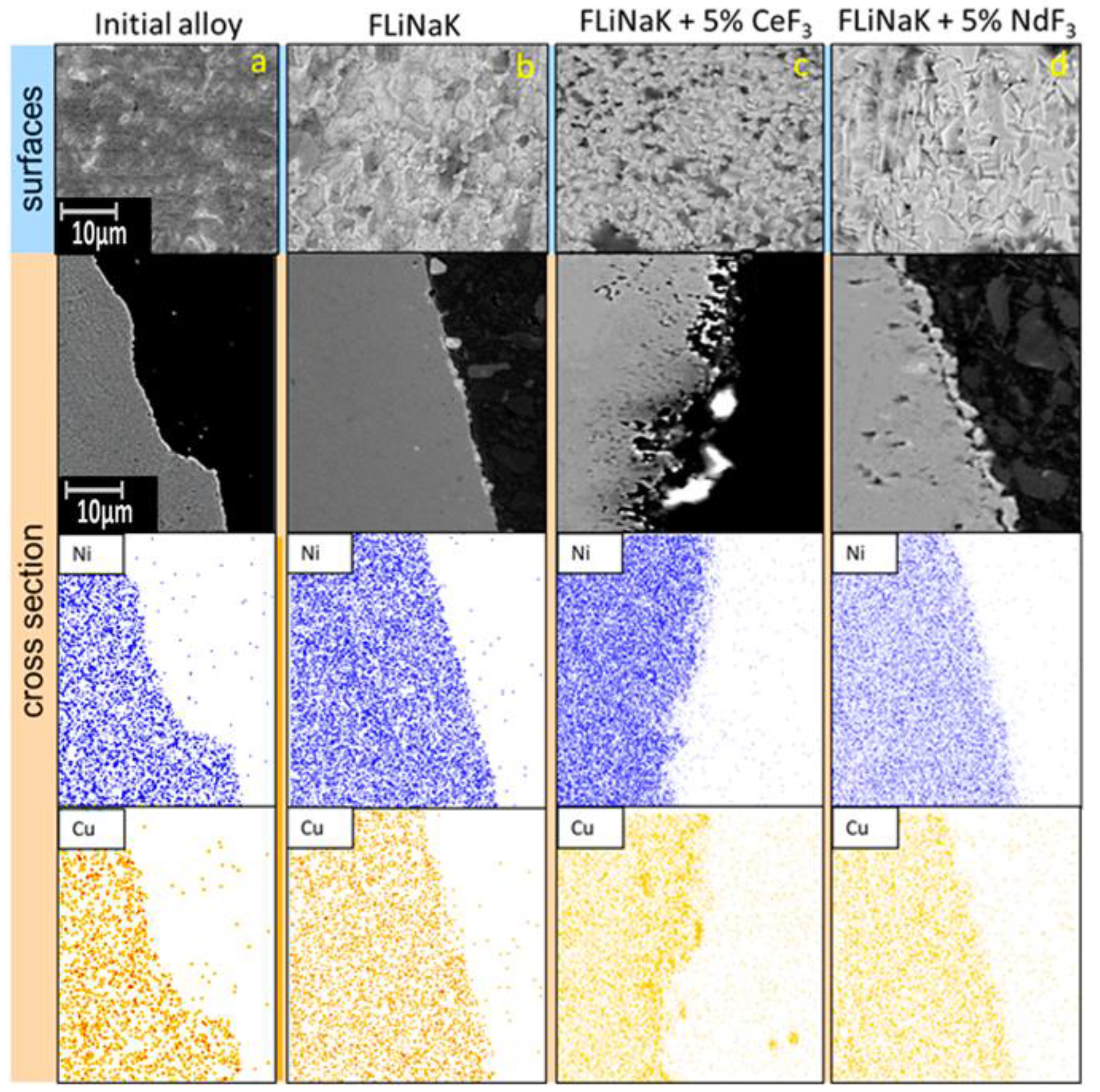
3.2. SEM of the Studied Samples

The analysis of the corresponding morphological changes in the surfaces of the studied samples was performed by EDX microanalyses of the samples’ surfaces and cross-sections. To clarify the elemental composition of the surface layer, element mapping of the sample cross-section was performed.
Figure 6 illustrates the samples of the surfaces and cross-sections for the steel exposed for 100 h in FLiNaK with the addition of cerium and neodymium fluorides at 550 °C.
The EDX microanalyses of the steel samples elucidated that during the corrosion exposure, the pitting corrosion points appeared at the sample’s surface. The addition of cerium fluoride caused the formation of subsurface cavities and significant chromium depletion of the subsurface layer of the alloy bulk. Such cavities may be formed by the development of the initial inter-crystalline corrosion. Addition of neodymium fluoride into the melt led to the formation of relatively deep selective corrosion damage. The ratio between nickel and iron ions remained almost unchanged in the subsurface volume. In other words, additions of cerium and neodymium fluorides into the melt increased the depth of corrosion points, their number, and size. The penetration depths, on average, were 6.2, 18.3, and 12.0 μm for the samples exposed in the FLiNaK, FLiNaK + (5 wt.%) CeF3, FLiNaK + (5 wt.%) NdF3, respectively. The number of local corrosion defects (per 100 μm2) /their size (μm) averages 8.1/0.9, 6.4/4.0, and 7.3/3.1 for samples exposed in FLiNaK, FLiNaK + (5 wt.%) CeF3, FLiNaK + (5 wt.%) NdF3, respectively.
Apart from that, the surface layer was subjected to large chromium depletion. There were clear signs of the inter-crystalline corrosion at the surface.
Figure 7 presents the SEM images of the surfaces and cross-sections for the Hastelloy C2000 samples that interact with the FLiNaK melt with CeF3 or NdF3 additions at 550 °C during 100 h.
Multiple localized corrosion points were present at the surface. The redistribution of the molybdenum concentration was observed in the subsurface material volume. The nickel concentration remained almost unchanged. Large chromium depletion was observed at the subsurface layer, which was especially seen at the addition of cerium cations into the melt.
The addition of cerium and neodymium fluorides into the salts’ media increased the candidate material degradation; large-size areas of pitting corrosion were observed alongside with the localized corrosion points as in the case of the samples exposed in lithium, potassium, and sodium fluorides. Apart from that, the element analysis determined that the chromium concentration decreased in the formed cavities and the molybdenum concentration increased near the cavities. On average, the depth of the corrosion was 8.5, 23.2, and 16.9 µm for the samples exposed in FLiNaK, FLiNaK + 5 wt.% CeF3, and FLiNaK + 5 wt.% NdF3, respectively.
The number of local corrosion defects (per 100 μm2)/their size (μm) averaged 6.5/1.1, 18.2/1.2, and 16.7/2.0 for samples exposed in FLiNaK, FLiNaK + (5 wt.%) CeF3, and FLiNaK + (5 wt.%) NdF3, respectively.
Figure 8 shows the images of the surface and cross-section of the Monel 404 samples exposed in the FLiNaK melt with the addition of cerium or neodymium fluorides.
Some localized corrosion points were observed at the samples’ surfaces. The addition of neodymium fluoride caused etching of the surface layer, which was observed at the surface cross-section; apart from that, the copper concentration in the subsurface layer was found to increase, which testified to the presence of the dissolution of a part of the nickel from the surface. The addition of neodymium fluoride into the melt caused insignificant fragmentary pitting corrosion. It should be noted that insignificant cavities appeared in the subsurface layer at the addition of cerium and neodymium fluorides. Their formation may be associated with the point etching of minor impurities (iron) from the alloy. On average, the corrosion depth was 0.3, 5.2, and 4.0 µm for the samples exposed in FLiNaK, FLiNaK + 5 wt.% CeF3, and FLiNaK + 5 wt.% NdF3, respectively. The number of local corrosion defects (per 100 μm2)/their size (μm) averaged 0/0, 7.3/1.7, and 2.4/0.7 for samples exposed in FLiNaK, FLiNaK + (5 wt.%) CeF3, and FLiNaK + (5 wt.%) NdF3, respectively.
Thus, it can be concluded that the addition of fluorides of f-elements significantly enhances the local corrosion of materials and increases the size of corrosion foci, their number, and depth.
Considering the data on the Monel 404 alloy, we concluded that the surface morphology was not subjected to any serious changes during the corrosion tests relative to the analogous experiments with the Hastelloy C2000 and 12Cr18Ni10Ti alloys.
We may conclude that Monel 404 demonstrates excellent corrosion resistance in the FLiNaK melt under the studied extremely aggressive conditions. Such a conclusion obtained by the EDX microanalysis is in agreement with the earlier obtained data by the gravimetric and chemical analyses.
However, the actual implementation of the MSR functional materials requires experiments with uranium and plutonium additions into the corrosion media alongside those using imitators of the fission products, i.e., cerium and neodymium.
The corrosion tests with irradiated materials are crucial, because the structure of a great number of materials is known to change under radiation. This may have a significant impact on the anticorrosive properties of the material.
Based on the calculations of the ion force of molten alkali fluorides containing desired concentrations of f-elements fluorides and correlation of the candidate materials according to their corrosion rates, we may conclude that cerium fluoride being a plutonium fluoride imitator creates the highest possible aggressiveness of the electrolyte as opposed to the FLiNaK with the addition NdF3. As a result of the performed tests, we may assume that the electrochemical mechanism of the studied corrosion processes has a limiting stage, that is the transition into the chromium and molybdenum salt phase that forms volatile fluorides of various compositions and oxidation degrees under studied temperatures. This causes the formation of subsurface cavities in the samples made of nickel–chromium–molybdenum alloys and pitting corrosion in the samples made of 12Cr18Ni10Ti steel.

4. Conclusions

Corrosion resistance of the studied materials was found to decrease in a row from Monel 404 > Hastelloy C2000 > 12Cr18Ni10Ti in a eutectic FLiNaK melt containing cerium fluoride as an imitator of plutonium trifluoride or neodymium fluoride as an imitator of uranium fluoride. Cerium fluoride caused a significantly greater change in the morphology of the candidate materials compared to neodymium fluoride. The addition of fluorides of f-elements significantly enhanced the local corrosion of materials and increased the size of corrosion spots, their number, and depth.
The samples of steel 12Cr18Ni10Ti were subjected to local cracking corrosion. The addition of cerium fluoride into the melt resulted in the additional etching of the alloy surface and deep chromium depletion of the surface. The addition of neodymium fluoride resulted in the formation of the point/inter-crystalline corrosion damage in the sample bulk.
The EDX microanalyses of the Hastelloy C2000 samples illustrated that local corrosion formed at the surface of the samples exposed in the eutectic molten salt electrolyte during the corrosion tests. The addition of cerium and neodymium fluorides resulted in the formation of subsurface vacancies and significant continuous chromium depletion of the subsurface alloy bulk. Moreover, the doping of cerium and neodymium fluorides into the melt increased the fraction of the yield of molybdenum and nickel in the electrolyte.
The samples made of Monel 404 demonstrated an outstanding corrosion resistance under the studied conditions. That is why Monel 404 may be considered a candidate material for molten salt reactors.

Author Contributions

Conceptualization, E.N. and E.K.; methodology, E.N.; software, E.K.; validation, E.N., K.K. and A.K.; formal analysis, N.M.; investigation, M.E.; resources, P.M.; data curation, A.M.; writing—original draft preparation, E.K.; writing—review and editing, P.C.; visualization, K.S.; supervision, E.N.; project administration, V.T.; funding acquisition, E.K. All authors have read and agreed to the published version of the manuscript.

Funding

The reported study was funded by RFBR and ROSATOM according to the research project № 20-21-00022.

Institutional Review Board Statement

Not applicable.

Informed Consent Statement

Not applicable.

Acknowledgments

The research was partially performed using the facilities of the Shared Access Centre Composition of compounds (SAC COC) of the Institute of High Temperature Electrochemistry of the Ural Branch of the Russian Academy of Sciences.

Conflicts of Interest

The authors declare no conflict of interest. The funders had no role in the design of the study; in the collection, analyses or interpretation of data; in the writing of the manuscript, or in the decision to publish the results.

References

  1. LeBlanc, D. Molten salt reactors: A new beginning for an old idea. Nucl. Eng. Des. 2010, 240, 1644–1656. [Google Scholar] [CrossRef]
  2. Komarov, V.E.; Smolenskiy, V.V.; Afonichkin, V.K. Prospects for the use of molten salts in radiochemical technologies. Melts 2000, 2, 59–65. [Google Scholar]
  3. Khokhlov, V.; Ignatiev, V.; Afonichkin, V. Evaluating physical properties of molten salt reactor fluoride mixtures. J. Fluor. Chem. 2009, 130, 30–37. [Google Scholar] [CrossRef]
  4. Ignatiev, V.V.; Kormilitsyn, M.V.; Kormilitsyna, L. Molten-salt reactor for nuclear fuel cycle closure on all actinides. At. Energy 2018, 125, 251–255. [Google Scholar] [CrossRef]
  5. Ignatiev, V.; Feynberg, O.; Gnidoi, I.; Merzlyakov, A. Molten salt actinide recycler and transforming system without and with Th-U support: Fuel cycle flexibility and key material properties. Ann. Nucl. Energy 2014, 64, 408–420. [Google Scholar] [CrossRef]
  6. Ponomarev, L.I.; Belonogov, M.N.; Volkov, I.A.; Simonenko, V.A.; Sheremet’eva, U.F. LiF–NaF–KF Eutectic Based Fast Molten-Salt Reactor as Np, Am, Cm Transmuter. At. Energy 2019, 126, 139–149. [Google Scholar] [CrossRef]
  7. Ignat’ev, V.V.; Feinberg, O.S.; Smirnov, V.P.; Vanyukova, G.V.; Lopatkin, A.V. Analysis of the Fuel-Loop Characteristics of a Molten-Salt Nuclear Reactor with a Cavity Core. At. Energy 2019, 126, 156–162. [Google Scholar] [CrossRef]
  8. Dolan, T.J. Molten Salt Reactors and Thorium Energy; Woodhead Publishing: Cambridge, MA, USA, 2017; Volume 1, pp. 452–540. [Google Scholar]
  9. Sridharan, K.; Allen, T.R.R. Corrosion in Molten Salts; Elsevier Inc.: Amsterdam, The Netherlands, 2013; Volume 1, pp. 241–267. [Google Scholar]
  10. Ignatiev, V.; Surenkov, A. 5–corrosion phenomena induced by molten salts in Generation IV nuclear reactors. Struct. Mater. Gener. IV Nucl. React. 2017, 1, 153–189. [Google Scholar]
  11. Raiman, S.S.; Sangkeun, L. Aggregation and data analysis of corrosion studies in molten chloride and fluoride salts. J. Nucl. Mater. 2018, 511, 523–535. [Google Scholar] [CrossRef]
  12. Guo, S.; Zhang, J.; Wub, W.; Zhou, W. Corrosion in the molten fluoride and chloride salts and materials development for nuclear applications. Prog. Mater. Sci. 2018, 97, 448–487. [Google Scholar] [CrossRef]
  13. Wang, Y.; Zhang, S.; Ji, X.; Wang, P.; Li, W. Material corrosion in molten fluoride salts. Int. J. Electrochem. Sci. 2018, 13, 4891–4900. [Google Scholar] [CrossRef]
  14. Wagner, C. The formation of thin oxide films on metals. Corros. Sci. 1973, 13, 23–52. [Google Scholar] [CrossRef]
  15. Young, D.J. High Temperature Oxidation and Corrosion of Metals; Elsevier Science: Oxford, UK, 2016; pp. 320–355. [Google Scholar]
  16. Azhazha, V.M.; Andriiko, A.A.; Bakai, A.S.; Volkov, S.V.; Devyatkin, S.V.; Dovbnya, A.N.; Lavrienenko, S.D.; Omelchuk, A.A.; Shirokov, B.M. Corrosion of irradiated Ni-Mo alloys in sodium fluoride-zirconium fluoride melt. Quest. Atom. Sci. Tech. 2005, 3, 134–139. [Google Scholar]
  17. Bakay, A.S.; Checkin, A.V.; Juk, V.V. Mekhanicheskiye. Fizicheskiye. Korrozionnyye i Radiatsionnyye Svoystva splavov tipa KHASTELLOY N v Rasplavakh Ftoridnykh soley: Obzor; NNC KHFTI: Kharkov, Ukraine, 2005. [Google Scholar]
  18. Serp, J.; Allibert, M.; Beneš, O.; Delpech, S.; Feynberg, O.; Ghetta, V.; Heuer, D.; Holcomb, D.; Ignatiev, V.; Kloosterman, J.L.; et al. The molten salt reactor (MSR) in generation IV: Overview and perspectives. Prog. Nucl. Energy 2014, 77, 308–319. [Google Scholar] [CrossRef]
  19. Williams, D.F. Assessment of Candidate Molten Salt Coolants for the Advanced High-Temperature Reactor (AHTR); Ridge National Laboratory: Oak Ridge, TN, USA, 2006; p. 86. [Google Scholar]
  20. Hogerton, J.F. Reactor Handbook: Materials; Technical Information Service, U.S. Atomic Energy Commission: Germantown, ML, USA, 1955; Volume 4. [Google Scholar]
  21. Manly, W.D.; Coobs, J.H.; DeVan, J.H.; Douglas, D.A.; Inui, H.; Patriarca, P.; Roche, T.; Scott, J. Metallurgical Problems in Molten Fluoride System. Nucl. Fuel React. Mater. 1959, 6, 36–52. [Google Scholar]
  22. Manly, W.D.; Adamson, G.M.; Coobs, J.H.; DeVan, J.H.; Douglas, D.A.; Hoffman, E.E.; Patriarca, P. Aircraft Reactor Experiment-Metallurgical Aspects; Ridge National Laboratory: Oak Ridge, TN, USA, 1957; p. 1. [Google Scholar]
  23. Ignatiev, V.; Surenkov, A.; Gnidoi, I.; Fedulov, V.; Uglov, V.; Afonichkin, V.; Bovet, A.; Subbotin, V.; Panov, A.; Toropov, A. Compatibility of Selected Ni-Based Alloys in Molten Li,Na,Be/F Salts with PuF3 and Tellurium Additions. Nucl. Technol. 2008, 164, 130–142. [Google Scholar] [CrossRef]
  24. Lizin, A.A.; Tomilin, S.V.; Gnevashov, O.E.; Gazizov, R.K.; Osipenko, A.G.; Kormilitsyn, M.V.; Baranov, A.A.; Zaharova, L.V.; Naumov, V.S.; Ponomarev, L.L. PuF3, AmF3, CeF3 and NdF3 solubility in LiF-NaF-KF melt. At. Energy 2013, 115, 11–17. [Google Scholar] [CrossRef]
  25. Belonogov, M.N.; Volkov, I.A.; Modestov, D.G.; Rykovanov, G.N.; Simonenko, V.A.; Khmel’nitskii, D.V. On an Optimal Minor-Actinide Transmutation Regime in a Molten-Salt Reactor. At. Energy 2020, 128, 143–150. [Google Scholar] [CrossRef]
  26. Ponomarev, L.I.; Seregin, M.B.; Mikhalichenko, A.A.; Parshin, A.P.; Zagorez, L.P. Validation of actinide fluoride simulators for studying solubility in fuel salt of molten-salt reactors. At. Energy 2012, 112, 417–422. [Google Scholar] [CrossRef]
  27. Nikitina, E.V.; Kazakovtseva, N.A.; Karfidov, E.A. Corrosion of 16Cr12MoWSVNbB (EP-823) steel in the LiCl-KCl melt containing CeCl3, NdCl3 and UCl3. J. Alloys Compd. 2019, 811, 152032. [Google Scholar] [CrossRef]
  28. Nikitina, E.V.; Kazakovtseva, N.A. Investigation of corrosion steel 12Cr18Ni10Ti in a melt LiCl-KCl-nNdCl3. Russ. Met. 2018, 8, 715–717. [Google Scholar]
  29. Nikitina, E.V.; Karfidov, E.A. Corrosion of construction materials of separator in molten carbonates of alkali metals. Int. J. Hydrog. Energy 2021, 46, 16925–16931. [Google Scholar] [CrossRef]
  30. Nikitina, E.V.; Kazakovtseva, N.A.; Maikov, M.A.; Malkov, V.B.; Karfidov, E.A.; Chuikin, A.Y. Electrochemical Corrosion Behavior of Monel Alloy in Carbonate Melts. Russ. J. Electrochem. 2018, 54, 697–701. [Google Scholar] [CrossRef]
  31. DeVan, J.H.; Evans, R.B. Corrosion Behavior of Reactor Materials in Fluoride Salt Mixtures; Ridge National Laboratory: Oak Ridge, TN, USA, 1962; Volume 1, pp. 3–35. [Google Scholar]
  32. Zheng, G.; He, L.; Carpenter, D.; Sridharan, K. Corrosion-induced microstructural developments in 316 stainless steel during exposure to molten Li2BeF4 (FLiBe) salt. J. Nucl. Mater. 2016, 482, 147–155. [Google Scholar] [CrossRef] [Green Version]
  33. Olson, L.C.; Ambrosek, J.W.; Sridharan, K.; Anderson, M.H.; Allen, T.R. Materials corrosion in molten LiF–NaF–KF salt. J. Fluor. Chem. 2009, 130, 67–73. [Google Scholar] [CrossRef]
  34. Kelleher, B.C.; Dolan, K.P.; Brooks, P.; Anderson, M.H.; Sridharan, K. Batch-Scale Hydrofluorination of Li2BeF4 to Support Molten Salt Reactor Development. J. Nucl. Eng. Radiat. Sci. 2015, 1, 1–12. [Google Scholar] [CrossRef]
  35. Zheng, G.; Kelleher, B.; Cao, G.; Anderson, M.; Allen, T.; Sridharan, K. Corrosion of 316 stainless steel in high temperature molten Li2BeF4 (FLiBe) salt. J. Nucl. Mater. 2015, 46, 143–150. [Google Scholar] [CrossRef]
  36. Keiser, J.R.; Manning, D.L.; Clausing, R.E. Corrosion resistance of some nickel base alloys to molten fluoride salts containing UF4 and tellurium in: Molten Salts. Electrochem. Soc. 1976, 6, 315–328. [Google Scholar] [CrossRef]
  37. Distefano, J.R.; DeVan, J.H.; Keiser, J.R.; Klueh, R.L.; Eatherly, W.P. Materials Considerations for Molten Salt Accelerator Based Plutonium Conversion Systems; Ridge National Laboratory: Oak Ridge, TN, USA, 1995; Volume 1, pp. 3–31. [Google Scholar]
  38. Keiser, J.R. Compatability studies of potential molten salt breeder reactor materials in molten fluoride salts. Met. Ceram. Div. 1977, 1, 1–21. [Google Scholar]
  39. Koger, J.W. Evaluation of Hastelloy N Alloy after Nine Years Exposure to Both a Molten Fluoride Salt and at Temperatures from 700 to 560 °C; Oak Ridge National Laboratory: Oak Ridge, TN, USA, 1972; Volume 1, pp. 1–35. [Google Scholar]
  40. Koger, J. Intergranular Corrosion of Hastelloy N; Oak Ridge National Laboratory: Oak Ridge, TN, USA, 1972; Volume 1, pp. 65–68. [Google Scholar]
  41. Koger, J.W.; Litman, A.P. Compatibility of Molybdenum-Base Alloy TZM, with LiFBeF2-ThF4-UF₄ (68–20–11.7–0.3 Mole Percent) at 1100 °C; Oak Ridge National Laboratory: Oak Ridge, TN, USA, 1969; Volume 1, pp. 1–11. [Google Scholar]
  42. Dai, Q.; Ye, X.X.; Ai, H.; Chen, S.; Jiang, L.; Liang, J.; Yu, K.; Leng, B.; Li, Z.; Zhou, X. Corrosion of Incoloy 800 H alloys with nickel cladding in FLiNaK salts at 850 °C. Corros. Sci. 2018, 133, 349–357. [Google Scholar] [CrossRef]
  43. Olson, L.C.; Fuentes, R.E.; Martinez-Rodriguez, M.J.; Ambrosek, J.W.; Sridharan, K.; Anderson, M.H.; Garcia-Diaz, B.L.; Gray, J.; Allen, T.R. Impact of corrosion test container material in molten fluorides. J. Sol. Energy Eng. 2015, 137, 1–8. [Google Scholar] [CrossRef]
  44. Dong, L.; Peng, Q.; Zhang, Z.; Shoji, T.; Han, E.H.; Ke, W.; Wang, L. Effect of dissolved hydrogen on corrosion of 316NG stainless steel in high temperature water. Nucl. Eng. Des. 2015, 295, 403–414. [Google Scholar] [CrossRef]
  45. Ye, X.X.; Ai, H.; Guo, Z.; Huang, H.F.; Jiang, L.; Wang, J.Q.; Li, Z.J.; Zhou, X.T. The hightemperature corrosion of Hastelloy N alloy (UNS N10003) in molten fluoride salts analysed by STXM, XAS, XRD, SEM, EPMA, TEM/EDS. Corros. Sci. 2016, 106, 249–259. [Google Scholar] [CrossRef]
  46. Ouyang, F.-Y.; Chang, C.-H.; You, B.-C.; Yeh, T.-K.; Kai, J.-J. Effect of moisture on corrosion of Ni-based alloys in molten alkali fluoride FLiNaK salt environments. J. Nucl. Mater. 2013, 437, 201–207. [Google Scholar] [CrossRef]
  47. Warchilováa, T.; Dillingerováa, V.; Škodac, R.; Šimod, T.; Matald, O.; Vaculoviča, T.; Kanickýa, V. Corrosion of nickel-based structural materials for nuclear reactors by molten fluoride salt: From bulk content of corrosion products to elemental imagingof corrosion changes. Spectrochim. Acta Part B 2018, 148, 113–117. [Google Scholar] [CrossRef]
  48. Chan, K.J.; Ambrecht, R.J.; Luong, J.M.; Choi, W.T.; Singh, P.M. Carburization effects on the corrosion of Cr, Fe, Ni, W, and Mo in fluoride-salt cooled high temperature reactor (FHR) coolant. Ann. Nucl. Energy 2018, 120, 279–285. [Google Scholar] [CrossRef]
  49. Delpech, S.; Cabet, C.; Slim, C.; Picard, G.S. Molten fluorides for nuclear applications. Mater. Today 2010, 13, 34–41. [Google Scholar] [CrossRef]
Figure 1. Micrographs of the surface (a), the cross-section (b), and the elemental composition (c) of the source material steel 12Cr18Ni10Ti.
Materials 15 00761 g001
Figure 2. Micrographs of the surface (a), the cross-section (b), and the elemental composition (c) of the source material Hastelloy C2000.
Materials 15 00761 g002
Figure 3. Micrographs of the surface (a), the cross-section (b), and the elemental composition (c) of the source material Monel 404.
Materials 15 00761 g003
Figure 4. Results of the chemical analysis.
Materials 15 00761 g004
Figure 5. Sampling results of the studied alloys: (a) 12Cr18Ni10Ti; (b) Hastelloy C2000; (c) Monel 404.
Materials 15 00761 g005aMaterials 15 00761 g005b
Figure 6. Structure of the surface layers of the 12Cr18Ni10Ti samples after long-term corrosion tests: (a) initial; (b) exposed in FLiNaK; (c) exposed in the FLiNaK + 5 wt.% CeF3 melt; (d) exposed in the FLiNaK + 5 wt.% NdF3 melt.
Materials 15 00761 g006
Figure 7. Structure of the surface layers of the samples of Hastelloy C2000 alloy after long-term corrosion tests: (a) initial; (b) exposed in FLiNaK; (c) exposed in the FLiNaK + 5 wt.% CeF3 melt; (d) exposed in the FLiNaK + 5 wt.% NdF3 melt.
Materials 15 00761 g007
Figure 8. Structure of the surface layers of the Monel 404 samples after long-term corrosion tests: (a) initial; (b) exposed in FLiNaK; (c) exposed in the FLiNaK + 5 wt.% CeF3 melt; (d) exposed in the FLiNaK + 5 wt.% NdF3 melt.
Materials 15 00761 g008
Table 1. Content of the components in the materials.
AlloyElements, wt.%
FeCSiMnNiSPCrTiWCuCoAlMo
Monel 404<0.5<0.15<0.1<0.152.0–57.0<0.024----Base-<0.05-
Hastelloy C2000<3.0<0.01<0.08<0.05Base<0.01<0.02522.0–24.0--1.3–1.9<2.0<0.515.0–17.0
Steel 12Cr18Ni10TiBase<0.08<0.8<2.09.0–11.0<0.02<0.03517.0–19.00.5–0.8-<0.1---
Table 2. Corrosion rate of the studied materials with an experiment time of 100 h.
Studied Fluoride MeltCorrosion Rate, g/m2h
Alloy
12Cr18Ni10TiHastelloy C2000Monel 404
FLiNaK0.806 ± 0.0400.597 ± 0.0300.122 ± 0.006
FLiNaK + 1 wt.% CeF31.260 ± 0.0630.857 ± 0.0430.222 ± 0.011
FLiNaK + 5 wt.% CeF31.483 ± 0.0740.948 ± 0.0470.294 ± 0.015
FLiNaK + 1 wt.% NdF31.138 ± 0.0570.805 ± 0.0400.137 ± 0.007
FLiNaK + 5 wt.% NdF31.303 ± 0.0650.854 ± 0.0430.167 ± 0.008
Publisher’s Note: MDPI stays neutral with regard to jurisdictional claims in published maps and institutional affiliations.

