
Removing Auxetic Properties in f.c.c. Hard Sphere Crystals by Orthogonal Nanochannels with Hard Spheres of Another Diameter

 , ,
, ,  , , ,
, , ,  and
and
Abstract
:1. Introduction
2. The Model
3. The Method
3.1. Theory
3.2. Simulations
4. Results and Discussion
5. Conclusions
Author Contributions
Funding
Institutional Review Board Statement
Informed Consent Statement
Data Availability Statement
Acknowledgments
Conflicts of Interest
Abbreviations
| PR | Poisson’s ratio |
| f.c.c. | face centered cubic |
| HS | Hard Sphere (potential) |
| MC | Monte Carlo |
References
- Landau, L.D.; Lifshitz, E.M. Theory of Elasticity; Pergamon Press: London, UK, 1986. [Google Scholar]
- Evans, K.E. Auxetic polymers: A new range of materials. Endeavour 1991, 15, 170–174. [Google Scholar] [CrossRef]
- Prawoto, Y. Seeing auxetic materials from the mechanics point of view: A structural review on the negative Poisson’s ratio. Comput. Mater. Sci. 2012, 58, 140–153. [Google Scholar] [CrossRef]
- Wojciechowski, K.W. Constant thermodynamic tension Monte Carlo studies of elastic properties of a two-dimensional system of hard cyclic hexamers. Mol. Phys. 1987, 61, 1247–1258. [Google Scholar] [CrossRef]
- Gibson, L.J.; Ashby, M.F. Cellular Solids: Structure and Properties; Pergamon Press: Oxford, UK, 1988. [Google Scholar]
- Wojciechowski, K.W. Two-dimensional isotropic model with a negative Poisson ratio. Phys. Lett. A 1989, 137, 60–64. [Google Scholar] [CrossRef]
- Bathurst, R.J.; Rothenburg, L. Note on a random isotropic granular material with negative Poisson’s ratio. Int. J. Eng. Sci. 1988, 26, 373–383. [Google Scholar] [CrossRef]
- Lakes, R.S. Foam structures with a negative Poisson’s ratio. Science 1987, 235, 1038–1040. [Google Scholar] [CrossRef]
- Mizzi, L.; Attard, D.; Casha, A.; Grima, J.N.; Gatt, R. On the suitability of hexagonal honeycombs as stent geometries. Phys. Status Solidi B Basic Solid State Phys. 2014, 251, 328–337. [Google Scholar] [CrossRef]
- Ren, X.; Shen, J.; Phuong, T.; Ngo, T.; Xie, Y.M. Auxetic nail: Design and experimental study. Comp. Struct. 2018, 184, 288–298. [Google Scholar] [CrossRef]
- Wang, Y.C.; Lai, H.W.; Ren, J.X. Enhanced Auxetic and Viscoelastic Properties of Filled Reentrant Honeycomb. Phys. Status Solidi B Basic Solid State Phys. 2020, 257, 1900184. [Google Scholar] [CrossRef]
- Zhang, X.Y.; Ren, X. A Simple Methodology to Generate Metamaterials and Structures with Negative Poisson’s Ratio. Phys. Status Solidi B Basic Solid State Phys. 2020, 257, 2000439. [Google Scholar] [CrossRef]
- Evans, K.E.; Alderson, A. Auxetic Materials: Functional Materials and Structures from Lateral Thinking! Adv. Mater. 2000, 12, 617–628. [Google Scholar] [CrossRef]
- Hoover, W.G.; Hoover, C.G. Searching for auxetics with DYNA3D and ParaDyn. Phys. Status Solidi B Basic Solid State Phys. 2005, 242, 585–594. [Google Scholar] [CrossRef] [Green Version]
- Ho, D.T.; Kim, H.; Kwon, S.Y.; Kim, S.Y. Auxeticity of face–centered cubic metal (001) nanoplates. Phys. Status Solidi B Basic Solid State Phys. 2015, 252, 1492–1501. [Google Scholar] [CrossRef]
- Tretiakov, K.V.; Piglowski, P.M.; Hyzorek, K.; Wojciechowski, K.W. Enhanced auxeticity in Yukawa systems due to introduction of nanochannels in [001]-direction. Smart Mater. Struct. 2016, 25, 054007. [Google Scholar] [CrossRef]
- Goldstein, R.V.; Gorodtsov, V.A.; Lisovenko, D.S.; Volkov, M.A. Two-Layered Tubes from Cubic Crystals: Auxetic Tubes. Phys. Status Solidi B Basic Solid State Phys. 2017, 254, 1600815. [Google Scholar] [CrossRef]
- Gorodtsov, V.A.; Volkov, M.A.; Lisovenko, D.S. Out-of-Plane Tension of Thin Two-Layered Plates of Cubic Crystals. Phys. Status Solidi B Basic Solid State Phys. 2021, 258, 2100184. [Google Scholar] [CrossRef]
- Ho, D.T.; Park, S.; Kwon, S.; Han, T.; Kim, S.Y. Negative Poisson’s ratio in cubic materials along principal directions. Phys. Status Solidi B Basic Solid State Phys. 2016, 253, 1288–1294. [Google Scholar] [CrossRef]
- Lisovenko, D.S.; Baimova, J.A.; Rysaeva, L.K.; Gorodtsov, V.A.; Rudskoy, A.I.; Dmitriev, S.V. Equilibrium diamond-like carbon nanostructures with cubic anisotropy: Elastic properties. Phys. Status Solidi B Basic Solid State Phys. 2016, 253, 1295–1302. [Google Scholar] [CrossRef]
- Grima-Cornish, J.N.; Vella-Żarb, L.; Wojciechowski, K.W.; Grima, J.N. Shearing deformations of β-cristobalite-like boron arsenate. Symmetry 2021, 13, 977. [Google Scholar] [CrossRef]
- Verma, P.; Shofner, M.L.; Lin, A.; Wagner, K.B.; Griffin, A.C. Induction of auxetic response in needle-punched nonwovens: Effects of temperature, pressure, and time. Phys. Status Solidi B Basic Solid State Phys. 2016, 253, 1270–1278. [Google Scholar] [CrossRef]
- Gao, Y.J.; Liu, S.; Wu, W.B.; Chen, X.G.; Studd, R. Manufacture and Evaluation of Auxetic Yarns and Woven Fabrics. Phys. Status Solidi B Basic Solid State Phys. 2020, 257, 1900112. [Google Scholar] [CrossRef]
- Farrugia, P.S.; Gatt, R.; Attard, D.; Attenborough, F.R.; Evans, K.E.; Grima, J.N. The Auxetic Behavior of a General Star-4 Structure. Phys. Status Solidi B Basic Solid State Phys. 2021, 258, 2100158. [Google Scholar] [CrossRef]
- Brańka, A.C.; Heyes, D.M.; Wojciechowski, K.W. Auxeticity of cubic materials under pressure. Phys. Status Solidi B Basic Solid State Phys. 2011, 248, 96–104. [Google Scholar] [CrossRef]
- Lakes, R.S. Advances in negative Poisson’s ratio materials. Adv. Mater. 1993, 5, 293–296. [Google Scholar] [CrossRef]
- Lakes, R. Negative-Poisson’s-Ratio Materials: Auxetic Solids. Annu. Rev. Mater. Res. 2017, 47, 63–81. [Google Scholar] [CrossRef]
- Lim, T.C. Mechanics of Metamaterials with Negative Parameters; Springer: Singapore, 2020. [Google Scholar]
- Dudek, K.K.; Gatt, R.; Dudek, M.R.; Grima, J.N. Controllable hierarchical mechanical metamaterials guided by the hinge design. Materials 2021, 14, 758. [Google Scholar] [CrossRef]
- Baughman, R.H.; Shacklette, J.M.; Zakhidov, A.A.; Stafstrom, S. Negative Poisson’s ratios as a common feature of cubic metals. Nature 1998, 392, 362–365. [Google Scholar] [CrossRef]
- Fozdar, D.Y.; Soman, P.; Lee, J.W.; Han, L.H.; Chen, S.C. Three-dimensional polymer constructs exhibiting a tunable negative Poisson’s ratio. Adv. Funct. Mater. 2011, 21, 2712–2720. [Google Scholar] [CrossRef]
- Alderson, K.; Nazaré, S.; Alderson, A. Large-scale extrusion of auxetic polypropylene fibre. Phys. Status Solidi B Basic Solid State Phys. 2016, 253, 1279–1287. [Google Scholar] [CrossRef]
- Alderson, K.L.; Simkins, V.R.; Coenen, V.L.; Davies, P.J.; Alderson, A.; Evans, K.E. How to make auxetic fibre reinforced composites. Phys. Status Solidi B Basic Solid State Phys. 2005, 242, 509–518. [Google Scholar] [CrossRef]
- Duncan, O.; Alderson, A.; Allen, T. Fabrication, characterization and analytical modeling of gradient auxetic closed cell foams. Smart Mater. Struct. 2021, 30, 035014. [Google Scholar] [CrossRef]
- Allen, T.; Hewage, T.; Newton–Mann, C.; Wang, W.; Duncan, O.; Alderson, A. Fabrication of Auxetic Foam Sheets for Sports Applications. Phys. Status Solidi B Basic Solid State Phys. 2017, 254, 1700596. [Google Scholar] [CrossRef] [Green Version]
- Wang, Y.C.; Shen, M.W.; Liao, S.M. Microstructural effects on the Poisson’s ratio of star-shaped two-dimensional systems. Phys. Status Solidi B Basic Solid State Phys. 2017, 254, 1700024. [Google Scholar] [CrossRef]
- Photiou, D.; Avraam, S.; Sillani, F.; Verga, F.; Jay, O.; Papadakis, L. Experimental and numerical analysis of 3d printed polymer tetra-petal auxetic structures under compression. Appl. Sci. 2021, 11, 10362. [Google Scholar] [CrossRef]
- Malfa, F.L.; Puce, S.; Rizzi, F.; Vittorio, M.D. A Flexible Carbon Nanotubes-Based Auxetic Sponge Electrode for Strain Sensors. Nanomaterials 2020, 10, 2365. [Google Scholar] [CrossRef]
- Chen, Y.Y.; Li, T.T.; Scarpa, F.; Wang, L.F. Lattice metamaterials with mechanically tunable Poisson’s ratio for vibration control. Phys. Rev. Appl. 2017, 7, 024012. [Google Scholar] [CrossRef] [Green Version]
- Li, D.; Yin, J.; Dong, L. Numerical analysis of a two-dimensional open cell topology with tunable Poisson’s ratio from positive to negative. Phys. Status Solidi-Rapid Res. Lett. 2018, 12, 1700374. [Google Scholar] [CrossRef]
- Usta, F.; Scarpa, F.; Turkmen, H.S.; Johnson, P.; Perriman, A.W.; Chen, Y.Y. Multiphase lattice metamaterials with enhanced mechanical performance. Smart Mater. Struct. 2021, 30, 025014. [Google Scholar] [CrossRef]
- Verma, P.; He, C.B.; Griffin, A.C. Implications for Auxetic Response in Liquid Crystalline Polymers: X-Ray Scattering and Space-Filling Molecular Modeling. Phys. Status Solidi B Basic Solid State Phys. 2020, 257, 2000261. [Google Scholar] [CrossRef]
- Iftekhar, H.; Khan, R.M.W.U.; Nawab, Y.; Hamdani, S.T.A.; Panchal, S. Numerical Analysis of Binding Yarn Float Length for 3D Auxetic Structures. Phys. Status Solidi B Basic Solid State Phys. 2020, 257, 2000440. [Google Scholar] [CrossRef]
- Gambin, D.; Dudek, K.K.; Dudek, M.R.; Grima, J.N.; Gatt, R. The mechanical properties of ice “X” with particular emphasis on its auxetic potential. J. Phys. Chem. Solids 2021, 150, 109717. [Google Scholar] [CrossRef]
- Czarnecki, S.; Lewinski, T. Pareto optimal design of non-homogeneous isotropic material properties for the multiple loading conditions. Phys. Status Solidi B Basic Solid State Phys. 2017, 254, 1600821. [Google Scholar] [CrossRef]
- Bacigalupo, A.; Lepidi, M.; Gnecco, G.; Gambarotta, L. Optimal design of auxetic hexachiral metamaterials with local resonators. Smart Mater. Struct. 2016, 25, 054009. [Google Scholar] [CrossRef] [Green Version]
- Pasternak, E.; Shufrin, I.; Dyskin, A.V. Thermal stresses in hybrid materials with auxetic inclusions. Comp. Struct. 2016, 138, 313–321. [Google Scholar] [CrossRef] [Green Version]
- Ho, D.T.; Nguyen, C.T.; Kwon, S.Y.; Kim, S.Y. Auxeticity in metals and periodic metallic porous structures induced by elastic instabilities. Phys. Status Solidi B Basic Solid State Phys. 2018, 256, 1800122. [Google Scholar] [CrossRef] [Green Version]
- Narojczyk, J.W.; Wojciechowski, K.W.; Tretiakov, K.V.; Smardzewski, J.; Scarpa, F.; Piglowski, P.M.; Kowalik, M.; Imre, A.R.; Bilski, M. Auxetic properties of a f.c.c. crystal of hard spheres with an array of [001]-nanochannels filled by hard spheres of another diameter. Phys. Status Solidi B Basic Solid State Phys. 2019, 256, 1800611. [Google Scholar] [CrossRef] [Green Version]
- Narojczyk, J.W.; Wojciechowski, K.W. Poisson’s ratio of the f.c.c. hard sphere crystals with periodically stacked (001)-nanolayers of hard spheres of another diameter. Materials 2019, 12, 700. [Google Scholar] [CrossRef] [Green Version]
- Narojczyk, J.W.; Wojciechowski, K.W.; J. Smardzewski, A.R.I.; Grima, J.N.; Bilski, M. Cancellation of auxetic properties in f.c.c. hard sphere crystals by hybrid layer-channel nanoinclusions filled by hard spheres of another diameter. Materials 2021, 14, 3008. [Google Scholar] [CrossRef]
- Nye, J.F. Physical Properties of Crystalls, Their Representation by Tensors and Matrices; Clarendon Press: Oxford, UK, 1957. [Google Scholar]
- Wiliams, J.S.; Poate, J.M. Ion Implantation and Beam Processing; Academic Press: London, UK, 1984. [Google Scholar]
- Nastasi, M.; Mayer, J.W. Ion Implantation and Synthesis of Materials; Springer: Berlin/Heidelberg, Germany, 2006. [Google Scholar]
- Morozow, D.; Barlak, M.; Werner, Z.; Pisarek, M.; Konarski, P.; Zagórski, J.; Rucki, M.; Chałko, L.; Łagodziński, M.; Narojczyk, J.; et al. Wear resistance improvement of cemented tungsten carbide deep-hole drills after ion implantation. Materials 2021, 14, 239. [Google Scholar] [CrossRef]
- Hansen, J.P.; McDonald, I.R. Theory of Simple Liquids; Academic Press: Amsterdam, The Netherlands, 2006. [Google Scholar]
- Frenkel, D. Order through entropy. Nat. Mater. 2015, 14, 9–12. [Google Scholar] [CrossRef]
- Wojciechowski, K.W.; Tretiakov, K.V.; Kowalik, M. Elastic properties of dense solid phases of hard cyclic pentamers and heptamers in two dimensions. Phys. Rev. E 2003, 67, 036121. [Google Scholar] [CrossRef] [PubMed] [Green Version]
- Tretiakov, K.V.; Wojciechowski, K.W. Auxetic, partially auxetic, and nonauxetic behaviour in 2D crystals of hard cyclic tetramers. Phys. Status Solidi-Rapid Res. Lett. 2020, 14, 2000198. [Google Scholar] [CrossRef]
- Tretiakov, K.V.; Wojciechowski, K.W. Poisson’s ratio of the fcc hard sphere crystal at high densities. J. Chem. Phys. 2005, 123, 074509. [Google Scholar] [CrossRef] [PubMed]
- Tretiakov, K.V.; Piglowski, P.M.; Narojczyk, J.W.; Wojciechowski, K.W. Selective enhancement of auxeticity through changing a diameter of nanochannels in Yukawa systems. Smart Mater. Struct. 2018, 27, 115021. [Google Scholar] [CrossRef]
- Parrinello, M.; Rahman, A. Polymorphic transitions in single crystals: A new molecular dynamics method. J. Appl. Phys. 1981, 52, 7182–7190. [Google Scholar] [CrossRef]
- Parrinello, M.; Rahman, A. Strain fluctuations and elastic constants. J. Chem. Phys. 1982, 76, 2662–2666. [Google Scholar] [CrossRef]
- Wojciechowski, K.W.; Brańka, A.C. Negative Poisson ratio in a two-dimensional isotropic solid. Phys. Rev. A 1989, 40, 7222–7225. [Google Scholar] [CrossRef]
- Tokmakova, S.P. Stereographic projections of Poisson’s ratio in auxetic crystals. Phys. Status Solidi B Basic Solid State Phys. 2005, 242, 721–729. [Google Scholar] [CrossRef]
- Tretiakov, K.V.; Wojciechowski, K.W. Partially auxetic behavior in fcc crystals of hard-core repulsive Yukawa particles. Phys. Status Solidi B Basic Solid State Phys. 2014, 251, 383–387. [Google Scholar] [CrossRef]


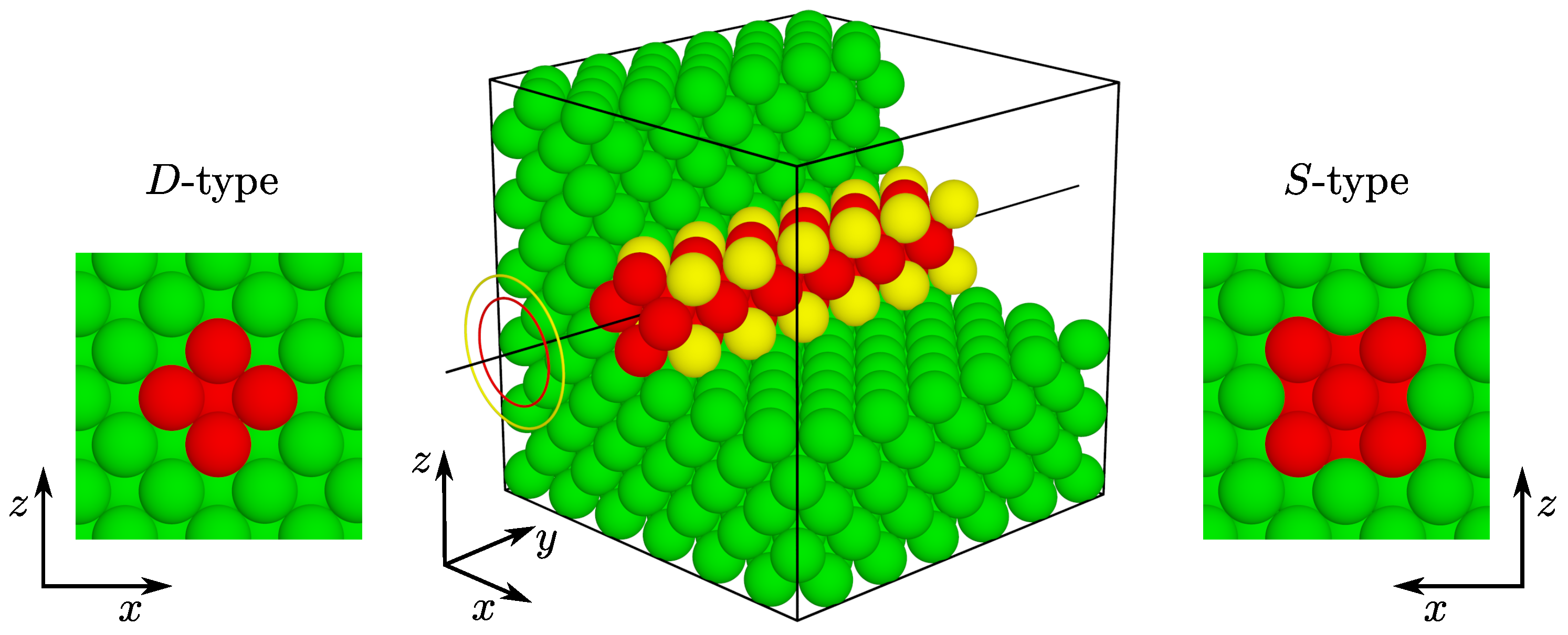
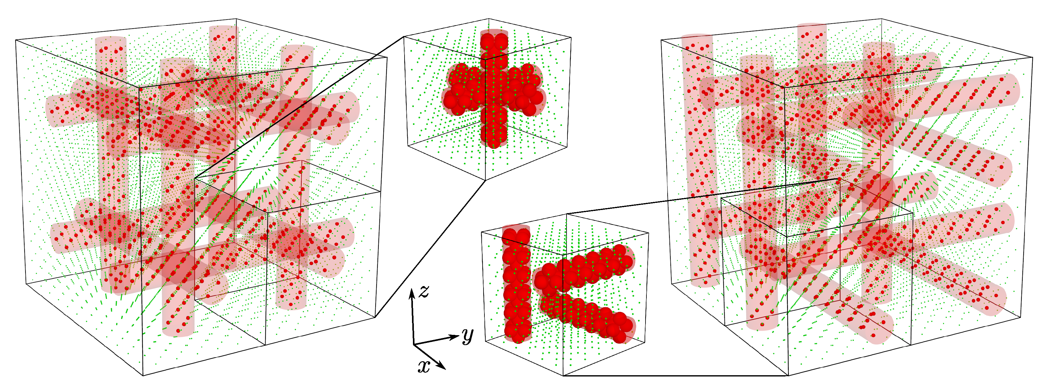
| Crossing Channels | Separate Channels | ||||
|---|---|---|---|---|---|
| Label | Diameter [] | [%] | [%] | ||
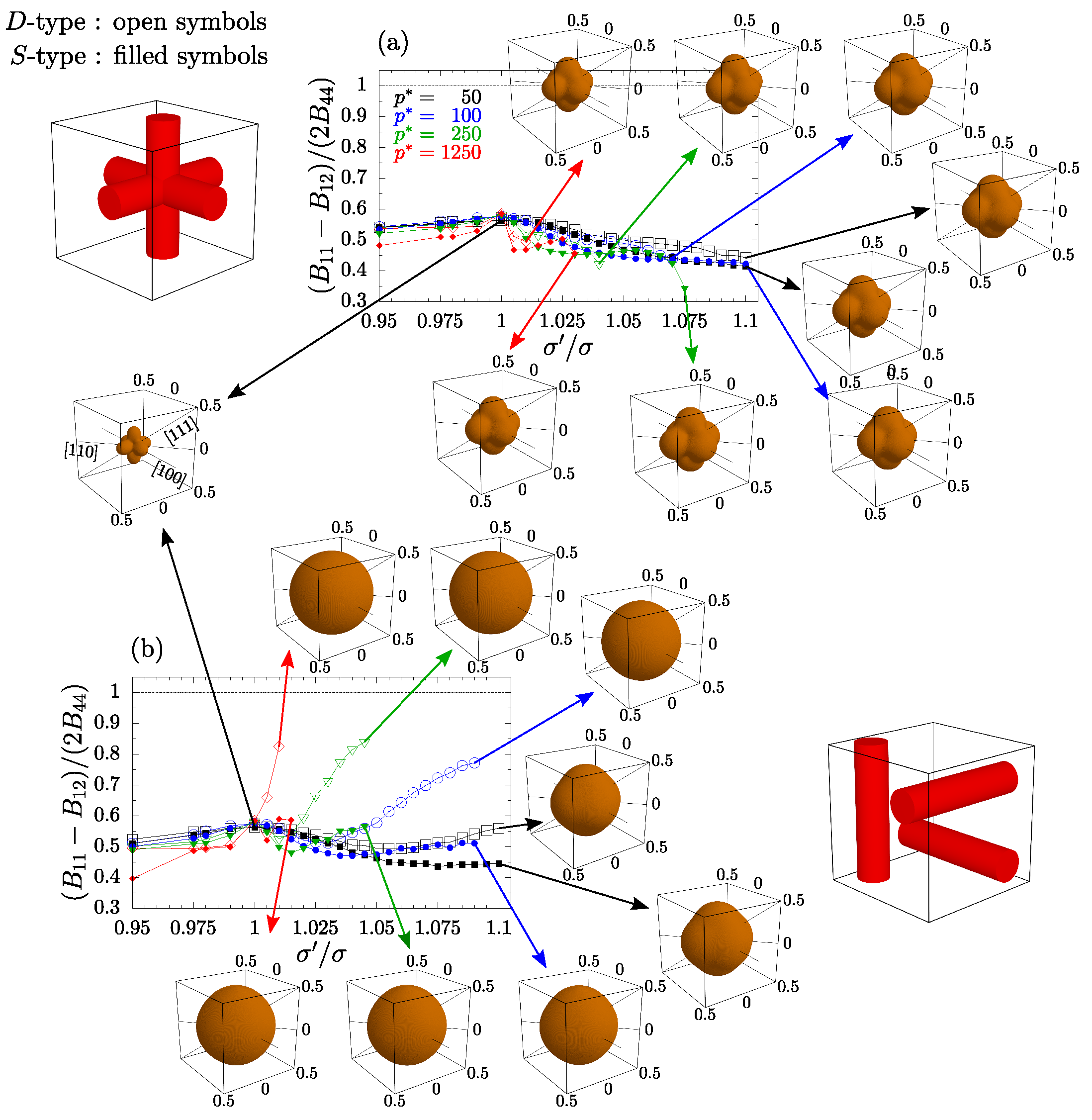
| D-type | 2 | 76 | 90 | 10.42 | |
| S-type | 136 | 162 | 18.75 | ||
Publisher’s Note: MDPI stays neutral with regard to jurisdictional claims in published maps and institutional affiliations. |
© 2022 by the authors. Licensee MDPI, Basel, Switzerland. This article is an open access article distributed under the terms and conditions of the Creative Commons Attribution (CC BY) license (https://creativecommons.org/licenses/by/4.0/).
Share and Cite
Narojczyk, J.W.; Bilski, M.; Grima, J.N.; Kędziora, P.; Morozow, D.; Rucki, M.; Wojciechowski, K.W. Removing Auxetic Properties in f.c.c. Hard Sphere Crystals by Orthogonal Nanochannels with Hard Spheres of Another Diameter. Materials 2022, 15, 1134. https://doi.org/10.3390/ma15031134
Narojczyk JW, Bilski M, Grima JN, Kędziora P, Morozow D, Rucki M, Wojciechowski KW. Removing Auxetic Properties in f.c.c. Hard Sphere Crystals by Orthogonal Nanochannels with Hard Spheres of Another Diameter. Materials. 2022; 15(3):1134. https://doi.org/10.3390/ma15031134
Chicago/Turabian StyleNarojczyk, Jakub W., Mikołaj Bilski, Joseph N. Grima, Przemysław Kędziora, Dmitrij Morozow, Mirosław Rucki, and Krzysztof W. Wojciechowski. 2022. "Removing Auxetic Properties in f.c.c. Hard Sphere Crystals by Orthogonal Nanochannels with Hard Spheres of Another Diameter" Materials 15, no. 3: 1134. https://doi.org/10.3390/ma15031134
APA StyleNarojczyk, J. W., Bilski, M., Grima, J. N., Kędziora, P., Morozow, D., Rucki, M., & Wojciechowski, K. W. (2022). Removing Auxetic Properties in f.c.c. Hard Sphere Crystals by Orthogonal Nanochannels with Hard Spheres of Another Diameter. Materials, 15(3), 1134. https://doi.org/10.3390/ma15031134