Article

Non-Volatile Memory and Synaptic Characteristics of TiN/CeOx/Pt RRAM Devices

Division of Electronics and Electrical Engineering, Dongguk University, Seoul 04620, Republic of Korea
*
Author to whom correspondence should be addressed.
These authors contributed equally to this work.
Materials 2022, 15(24), 9087; https://doi.org/10.3390/ma15249087
Submission received: 19 November 2022 / Revised: 13 December 2022 / Accepted: 16 December 2022 / Published: 19 December 2022
(This article belongs to the Special Issue Memristive Materials and Devices)

Abstract

:
In this study, we investigate the synaptic characteristics and the non-volatile memory characteristics of TiN/CeOx/Pt RRAM devices for a neuromorphic system. The thickness and chemical properties of the CeOx are confirmed through TEM, EDS, and XPS analysis. A lot of oxygen vacancies (ions) in CeOx film enhance resistive switching. The stable bipolar resistive switching characteristics, endurance cycling (>100 cycles), and non-volatile properties in the retention test (>10,000 s) are assessed through DC sweep. The filamentary switching model and Schottky emission-based conduction model are presented for TiN/CeOx/Pt RRAM devices in the LRS and HRS. The compliance current (1~5 mA) and reset stop voltage (−1.3~−2.2 V) are used in the set and reset processes, respectively, to implement multi-level cell (MLC) in DC sweep mode. Based on neural activity, a neuromorphic system is performed by electrical stimulation. Accordingly, the pulse responses achieve longer endurance cycling (>10,000 cycles), MLC (potentiation and depression), spike-timing dependent plasticity (STDP), and excitatory postsynaptic current (EPSC) to mimic synapse using TiN/CeOx/Pt RRAM devices.

1. Introduction

Recently, the amount of data and information have increased significantly with the development of new technologies such as artificial intelligence (AI) and the internet of thing (IoT) [1,2]. Therefore, data program/erase/read speed, power consumption, and operating voltage become significantly important. However, conventional memory devices such as flash memory have disadvantages in delaying memory access time because of their serial processing of information [3]. The human brain, which consists of approximately 1012 neurons and 1015 synapses, can compute and memorize data simultaneously in the same place [4,5]. Therefore, neuromorphic system devices, which mimic a biological system with parallel processing, are more suitable for energy-efficient and fast computing processing [6,7]. These devices are imitated by remembering, learning, and recognizing the functions of the human brain using neurons and synapses [8,9]. Resistive random-access memory (RRAM), which emulates the functionality of synaptic devices, has attracted enormous attention in the field of non-volatile memory (NVM) applications [10,11,12]. RRAM has several advantages, including long data retention, fast switching speed, long program/erase cycle endurance, and multi-level cell (MLC) capability [13].
The switching process of the RRAM is to change the resistance by applying an external voltage [14,15,16,17,18]. In other words, the RRAM stores “0” in the high resistance state (HRS) and “1” in the low resistance state (LRS). This resistive switching operation is possible because of the resistance change of the insulator in RRAM with bias. The sputtering system, which is a physical vapor deposition (PVD) technique for metal oxide deposition, permits several defects such as oxygen vacancies and grain boundaries [19,20,21]. Among them, the oxygen vacancies can be moved by an electrical force, providing a conducting path for electrons to flow [22]. There are major parameters in electrical signals such as voltage, time (width), and compliance current. By adjusting these parameters, the number of oxygen vacancies can be varied. The controlled vacancies exhibit multi-states rather than a simple “0” or “1” state [23]. As a synaptic device, the RRAM should represent the conductance for the weight of the synapse and should be implemented when the synapse (device) is stimulated (electrical signal). Excitatory postsynaptic current (EPSC) that is as conductance becomes fire indicates signal transmission in artificial neural networks [24,25]. In addition, continuously accumulated conductance is termed potentiation, and decreasing conductance is termed depression. Potentiation and depression are related to synaptic characteristics [26].
RRAM device consists of an insulating film sandwiched between two metal electrodes, which is called a metal-insulator-metal (MIM) structure [27]. The resistive switching properties are dependent on the material used for the metal electrode and the insulating layer. Various materials are used in insulator films, and transition metal oxides (TMO) are one of the most promising types. Because of its high compatibility, binary transition metal oxides, such as TaOx [28], NiO [29], TiO x [30], and HfO x [31,32] have been studied. However, recent research results show that many rare-earth metal oxides, such as Gd2O3 [33], CeO2 [34], and Sm2O3 [35] also exhibit good resistive switching properties for NVM. Among them, the CeO x thin films have attracted significant attention, owing to their strong ability to conduct oxygen ions or oxygen vacancy for RRAM devices [36,37]. The reaction of Pt and Al as top electrodes on the switching behavior of CeO2 films has also been studied [38,39]. In addition, the generation of oxygen vacancies was attributed to the effect between the CeO x and TiN bottom layers when TiN was used as the bottom layer [40]. However, the resistive switching characteristics of CeO x thin films still need to be studied systematically in various device configurations by using assorted top/bottom electrode materials.
This study reports on the effect of rare-earth transition metal oxides CeOx films on synaptic properties and DC properties. The device is composed of a TiN material as the top electrode and Pt material as the bottom electrode. The top/bottom electrode materials influence the window and stability of the resistive switching. We report excellent bipolar switching properties in TiN/CeOx/Pt memory devices, which can provide a clear perception of the switching process and attractive options of dielectric materials for RRAM applications.

2. Experiments

The fabrication process of the TiN/CeOx/Pt device is as follows: a ~100-nm-thick Pt/Ti layer was formed as the bottom electrode on a SiO2/Si substrate wafer by a sputtering system. The Ti layer acts as an adhesion layer between Pt and SiO2, regardless of the electrical characteristics. After that, a ~20 nm CeOx switching layer was deposited by a reactive sputtering system using a 3-inch Ce target. The Ar flow rate was 20 sccm, the O2 flow rate was 6 sccm, and the working pressure was 5 mTorr during sputtering at room temperature (RT). Finally, to deposit the top electrode with a thickness of 100 nm, a Ti metal target was reactive sputtered in an ambiance of N2 and Ar gases. The photolithography and lift-off process was performed to separate the cells from each other when depositing the top electrode. The square cell area is 100 μm × 100 μm. To analyze the electrical characteristics, Keithley’s 4200-SCS and 4225-PMU semiconductor parameter modules were utilized for DC sweep and pulse switching, respectively. The ground was applied to Pt BE while voltage bias was applied to TiN TE.

3. Results and Discussions

Figure 1a shows the schematic of the fabricated RRAM device. The TiN top electrode on the CeOx layer is separated at regular intervals to operate resistive switching in a cell of 100 × 100 μm area. Figure 1b shows the transmission electron microscopy (TEM) image and the energy dispersive spectrometer (EDS) mapping of the TiN/CeOx/Pt stack. The thickness of the CeOx layer is approximately 20 nm. Figure 1c,d shows the X-ray photoelectron spectroscopy (XPS) binding energy profiles of Ce 3d and O 1s for CeOx insulator film. Figure 1c shows the Ce3+ and Ce4+ spectra in the XPS spectra of Ce 3d. This indicates that a non-stoichiometric state CeOx film was deposited (1.3 < x < 2) [38]. Figure 1d shows the O 1s spectrum. The O 1s spectrum can be fitted by two peaks, corresponding to the binding energies of approximately 528.5 and 530.7 eV. In the binding energies of the two peaks, the higher energy (green fitting line) is assigned to O1− ions, and the other binding energy (sky blue fitting line) is assigned to O2− ions. The O1− ions and O2− ions denote the non-lattice oxygen and lattice oxygen, respectively [41,42]. The non-lattice oxygen ions contribute to resistive switching. In addition, the atomic concentration is calculated, and the result shows that the ratio of O to Ce is approximately 1.69 in CeOx bulk.
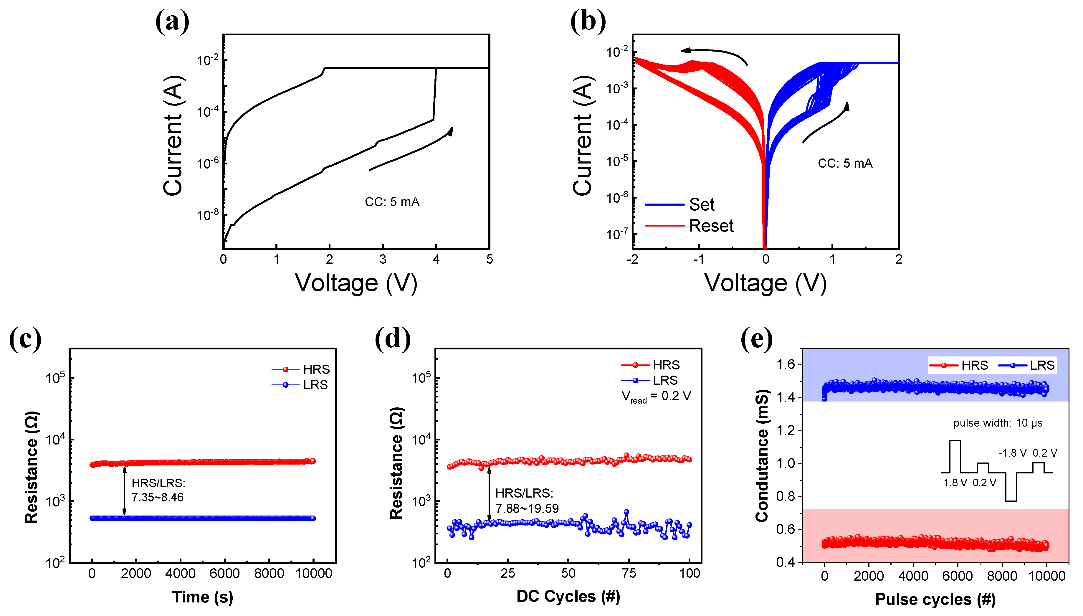
Figure 2a shows the I-V curve of the forming process of the device. Initially, an extremely high current flows, indicating that the CeOx layer has many oxygen vacancies. Figure 2b shows the repetitive I-V curves of the TiN/CeOx/Pt device. The set and reset process occurs repetitively by the positive bias and negative bias, respectively. The current begins to increase noticeably between 0.5 V and 1 V and is limited by a compliance current of 3 mA. The set process changes the device state from a high-resistance state (HRS) to a low-resistance state (LRS) by increasing the conducting defects in the CeOx layer. The oxygen vacancies (ions) near the interface of the CeOx and Pt (TiN) layer increase during the set process [43]. At positive bias voltage, the current in the backward sweep is higher than the current in the forward sweep for resistive memory switching. On the contrary, the reset process occurs when a negative bias is applied to the device. A gradual resistance change is observed during the reset process. The resistance in the RRAM device increases by the recombination between the oxygen and oxygen vacancies. In addition, the set voltage is significantly lowered in the paper reported Pt/CeOx/Pt [44] with only different top electrodes. This phenomenon allows the TiN to absorb oxygen ions and can operate the device as LRS at low voltage. Non-volatile memory properties in the LRS and HRS are verified by a retention test. HRS and LRS are nearly constant without degradation for 10,000 s, as shown in Figure 2c. Moreover, Figure 2d,e shows the endurance cycle test by DC sweep and pulse mode, respectively. The LRS and HRS at the reading of 0.2 V have enough on/off ratio (>10) for 100 cycles in DC mode. In pulse mode, the conductance ratio (LRS and HRS) exhibits identical stability.
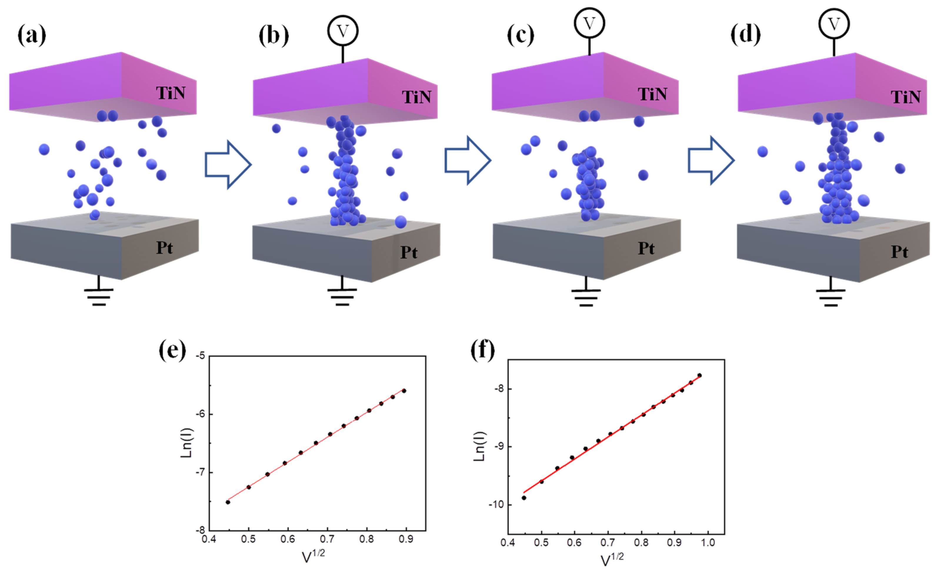
Figure 3a–d shows the schematics of resistive switching based on the filamentary model for the TiN/CeOx/Pt device. The CeOx layer has many oxygen vacancies in the initial state owing to the reactive sputtering (PVD), as shown in Figure 3a. The oxygen vacancies form the conducting path at a specific threshold voltage. It is usually known as the electroforming process or soft breakdown in Figure 3b. Subsequently, the filament is partially ruptured by the reset process, as shown in Figure 3c. At this time, the oxygen ions (anions) and the oxygen vacancies (cations) are electrically bonded [45]. Conversely, in Figure 3d, the filament gap is refilled by the set process again. The gap could be related to the Schottky barrier, which is verified by the fitting of ln(I) versus V1/2 in Figure 3e,f [39].
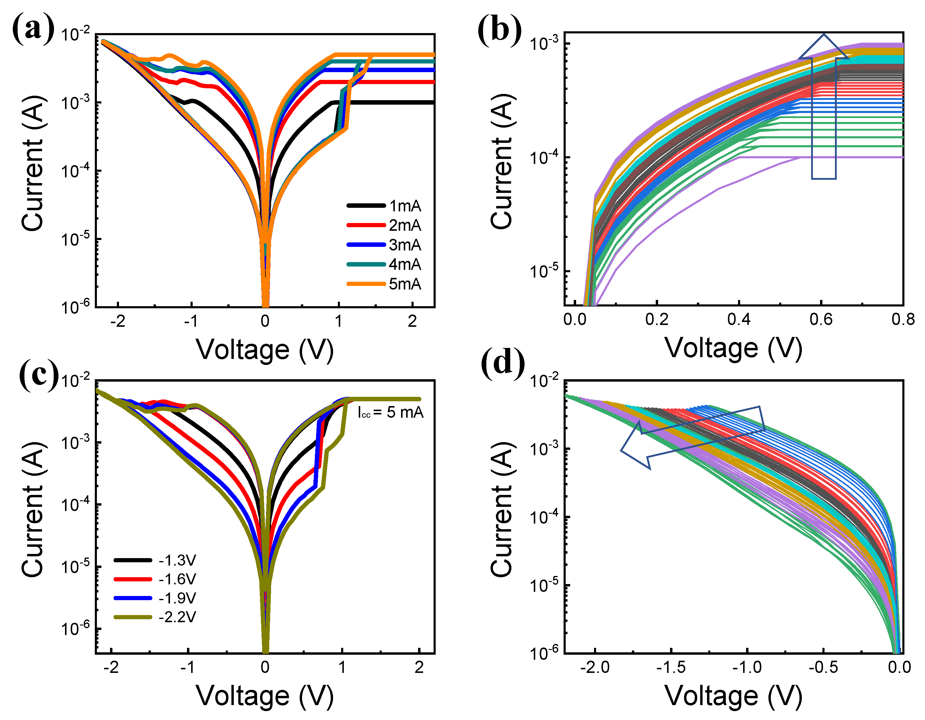
Next, we demonstrate the MLC by controlling the compliance current and resetting the stop voltage in the DC sweep. Figure 4a shows the I-V characteristics with different compliance current conditions (1 mA, 2 mA, 3 mA, 4 mA, and 5 mA) and the same reset stop voltage of −2 V. As the compliance current increases, the LRS current increases. However, the HRS current always returns to an almost constant value by the same reset stop voltage. Moreover, the fine control of the resistance state is achieved by compliance current, as shown in Figure 4b. The compliance current is varied from 0.1 mA to 1 mA in increments of 0.025 mA. As the compliance current increases, it is confirmed that the current generally increases. Figure 4c shows the I-V characteristics by controlling the reset stop voltage (−1.3 V, −1.6 V, −1.9 V, and −2.2 V) with the fixed compliance current (5 mA). The current decreases on increasing the absolute voltage of the reset stop voltage. However, the LRS current is maintained constant by controlling the same compliance current. Moreover, we demonstrate the clear adjustment of the current by changing the reset stop voltage from −1.25 V to −2.2 V in increments of −0.025 V. In this case, a more gradual reset transition is observed as compared to the set transition.
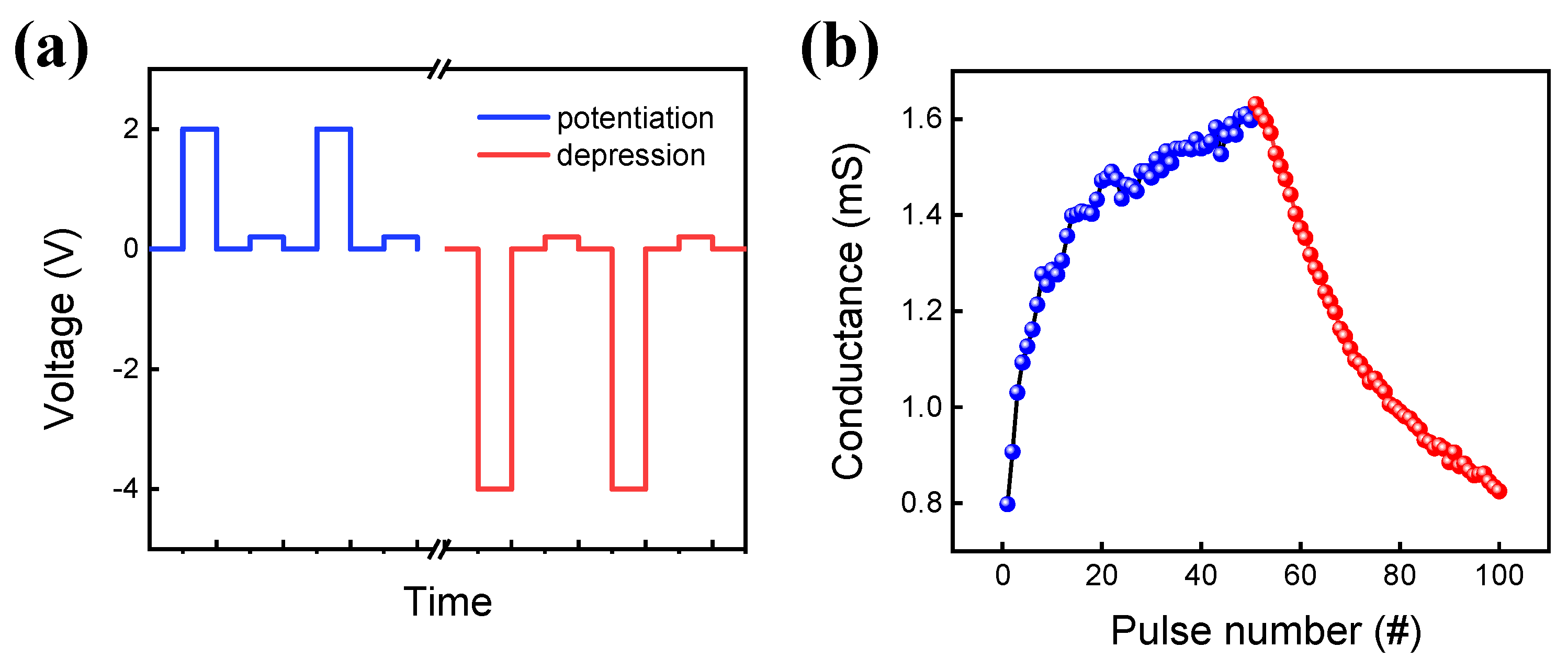
Next, we study the conductance control by a pulse for a more practical measurement system. Firstly, the pulse endurance is performed by a set pulse of 1.8 V and a reset pulse of −1.8 V with a pulse width of 10 μs, as shown in Figure 5a. The voltage of the read pulse is 0.2 V to minimize the read disturbance on the RRAM device. The long switching (10,000 cycles) in the pulse mode [46] can be endured although the on/off ratio is smaller than that of DC endurance. Figure 5b shows the potentiation and depression curves that are essential to implement the hardware-based neuromorphic system [47]. The set pulse (amplitude voltage: 1.8 V, width: 100 μs) and reset pulse (amplitude voltage: −1.8 V, width: 100 μs) are used for potentiation and depression, respectively.
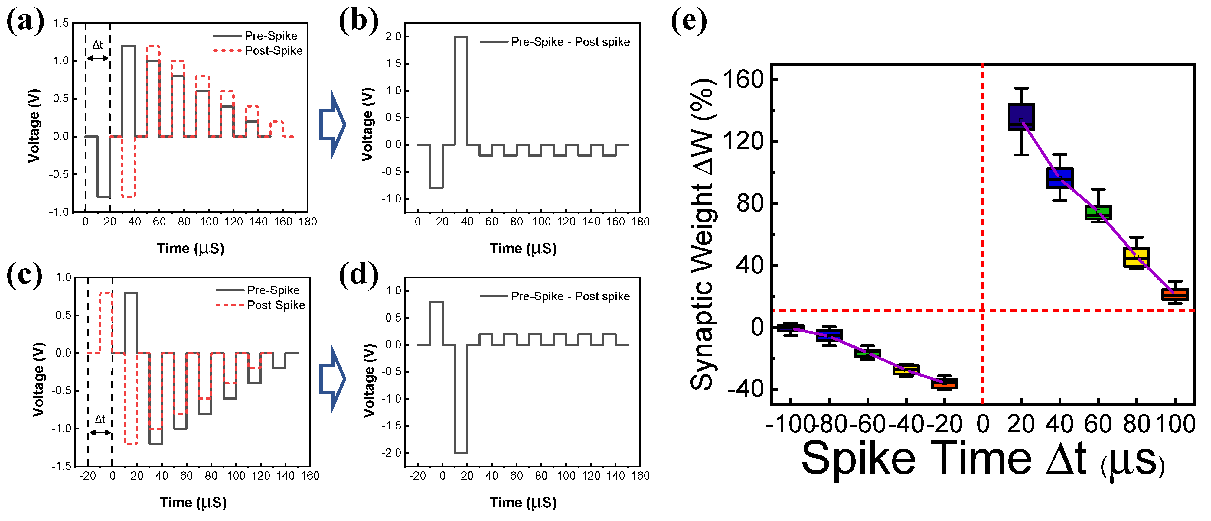
Finally, we emulate the spike-timing dependent plasticity (STDP) and excitatory postsynaptic current (EPSC) of biological synapses using the gradual resistive switching characteristics of the RRAM device. STDP is a biological process that controls the strength of the connections between neurons via synapses in the brain. The basic rule of STDP is based on the relative timing of a particular neuron’s input spike and output spike.
As the time interval decreases, the synaptic weight increases. EPSC is a postsynaptic potential that induces the postsynaptic neuron to easily fire an action potential [48]. Figure 6a,b shows the overlap of pulse trains for potentiation in which the effective set pulse is applied to the device. The overlapped pulse indicates that a pre-spike appears before the post-spike by Δt. Similarly, Figure 6c,d shows the overlap of pulse trains that a pre-spike appears after post-spike for depression. A negative voltage is effectively applied to the devices. Figure 6e shows the STDP characteristics by applying a pulse train consisting of five pulses on the device. Spike-timing-dependent synaptic weight is well emulated in the RRAM device. Figure 7a,b shows the change in the synaptic weight as a function of pulse voltage for EPSC. The change in the synaptic weight increases with increasing the absolute value of the voltage for both positive and negative voltage regimes.

4. Conclusions

The resistive switching characteristics of TiN/CeOx/Pt RRAM devices are investigated for non-volatile memory and neuromorphic system applications. The I-V curves are obtained by DC sweep for bipolar resistive switching. Moreover, 100 cycles of repetitive DC endurance and stable retention for 10,000 s are demonstrated to prove the reliability of the RRAM as a memory device. The filamentary switching with gap and Schottky emission-based conduction models that indicate resistive switching possibility are also presented. The compliance current and reset stop voltage to implement MLC could control the gradual resistance change in the set and reset processes. Compared to the set transition, a more gradual reset transition is exhibited. Furthermore, stable longer pulse endurance and MLC are obtained not only in DC mode but also in pulse mode by set and reset pulses. Finally, STDP and EPSC in biological systems are mimicked using TiN/CeOx/Pt RRAM devices for neuromorphic systems. The larger change in the synaptic weight is observed as the interval time between the pair stimuli is shorter or the stimuli are stronger.

Author Contributions

H.H. and J.P.: designed the experiment, conducted the electrical measurements, and wrote the original manuscript; Y.L.: validation; S.K.: visualization, supervision, and project administration. All authors have read and agreed to the published version of the manuscript.

Funding

This work was supported, in part, by the National Research Foundation of Republic of Korea (NRF), grant funded by the Korean government (MSIP) under Grant 2021R1C1C1004422 and Korea Institute of Energy Technology Evaluation and Planning (KETEP) grant funded by the Republic of Korea government (MOTIE) under Grant 20224000000020.

Institutional Review Board Statement

Not applicable.

Informed Consent Statement

Not applicable.

Data Availability Statement

Not applicable.

Conflicts of Interest

The authors declare no conflict of interest.

References

  1. Zhang, Z.; Wang, Z.; Shi, T.; Bi, C.; Rao, F.; Cai, Y.; Liu, Q.; Wu, H.; Zhou, P. Memory Materials and Devices: From Concept to Application. InfoMat 2020, 2, 261–290. [Google Scholar] [CrossRef] [Green Version]
  2. Atzori, L.; Iera, A.; Morabito, G. The Internet of Things: A Survey. Comput. Netw. 2010, 54, 2787–2805. [Google Scholar] [CrossRef]
  3. Zahoor, F.; Azni Zulkifli, T.Z.; Khanday, F.A. Resistive Random Access Memory (RRAM): An Overview of Materials, Switching Mechanism, Performance, Multilevel Cell (Mlc) Storage, Modeling, and Applications. Nanoscale Res. Lett. 2020, 15, 90. [Google Scholar] [CrossRef] [PubMed]
  4. Lin, Y.; Zeng, T.; Xu, H.; Wang, Z.; Zhao, X.; Liu, W.; Ma, J.; Liu, Y. Transferable and Flexible Artificial Memristive Synapse Based on WOx Schottky Junction on Arbitrary Substrates. Adv. Electron. Mater. 2018, 4, 1800373. [Google Scholar] [CrossRef]
  5. Hu, D.C.; Yang, R.; Jiang, L.; Guo, X. Memristive Synapses with Photoelectric Plasticity Realized in ZnO1−x/AlOy Heterojunction. ACS Appl. Mater. Interfaces 2018, 10, 6463–6470. [Google Scholar] [CrossRef]
  6. Park, M.; Kang, M.; Kim, S. Pulse Frequency Dependent Synaptic Characteristics in Ta/SiN/Si Memristor Device for Neuromorphic System. J. Alloys Compd. 2021, 882, 160760. [Google Scholar] [CrossRef]
  7. Lu, K.; Li, Y.; He, W.F.; Chen, J.; Zhou, Y.X.; Duan, N.; Jin, M.M.; Gu, W.; Xue, K.H.; Sun, H.J.; et al. Diverse Spike-Timing-Dependent Plasticity Based on Multilevel HfOx Memristor for Neuromorphic Computing. Appl. Phys. A Mater. Sci. Process. 2018, 124, 438. [Google Scholar] [CrossRef]
  8. Kim, S.; Jung, S.; Kim, M.H.; Chen, Y.C.; Chang, Y.F.; Ryoo, K.C.; Cho, S.; Lee, J.H.; Park, B.G. Scaling Effect on Silicon Nitride Memristor with Highly Doped Si Substrate. Small 2018, 14, e1704062. [Google Scholar] [CrossRef]
  9. Sun, B.; Zhou, G.; Guo, T.; Zhou, Y.N.; Wu, Y.A. Biomemristors as the next Generation Bioelectronics. Nano Energy 2020, 75, 104938. [Google Scholar] [CrossRef]
  10. Guo, T.; Sun, B.; Ranjan, S.; Jiao, Y.; Wei, L.; Norman Zhou, Y.; Wu, Y.A. From Memristive Materials to Neural Networks. ACS Appl. Mater. Interfaces 2020, 12, 54243–54265. [Google Scholar] [CrossRef]
  11. Mikhaylov, A.; Belov, A.; Korolev, D.; Antonov, I.; Kotomina, V.; Kotina, A.; Gryaznov, E.; Sharapov, A.; Koryazhkina, M.; Kryukov, R.; et al. Multilayer Metal-Oxide Memristive Device with Stabilized Resistive Switching. Adv. Mater. Technol. 2020, 5, 1900607. [Google Scholar] [CrossRef]
  12. Wan, W.; Kubendran, R.; Schaefer, C.; Eryilmaz, S.B.; Zhang, W.; Wu, D.; Deiss, S.; Raina, P.; Qian, H.; Gao, B.; et al. A Compute-in-Memory Chip Based on Resistive Random-Access Memory. Nature 2022, 608, 504–512. [Google Scholar] [CrossRef] [PubMed]
  13. Khan, R.; Ilyas, N.; Shamim, M.Z.M.; Khan, M.I.; Sohail, M.; Rahman, N.; Khan, A.A.; Khan, S.N.; Khan, A. Oxide-Based Resistive Switching-Based Devices: Fabrication, Influence Parameters and Applications. J. Mater. Chem. C Mater. 2021, 9, 15755–15788. [Google Scholar] [CrossRef]
  14. Strukov, D.B.; Snider, G.S.; Stewart, D.R.; Williams, R.S. The Missing Memristor Found. Nature 2008, 453, 80–83. [Google Scholar] [CrossRef]
  15. Ryu, H.; Kim, S. Pseudo-Interface Switching of a Two-Terminal Taox/Hfo2 Synaptic Device for Neuromorphic Applications. Nanomaterials 2020, 10, 1550. [Google Scholar] [CrossRef]
  16. Shen, Z.; Zhao, C.; Qi, Y.; Xu, W.; Liu, Y.; Mitrovic, I.Z.; Yang, L.; Zhao, C. Advances of RRAM Devices: Resistive Switching Mechanisms, Materials and Bionic Synaptic Application. Nanomaterials 2020, 10, 1437. [Google Scholar] [CrossRef]
  17. Kim, K.H.; Gaba, S.; Wheeler, D.; Cruz-Albrecht, J.M.; Hussain, T.; Srinivasa, N.; Lu, W. A Functional Hybrid Memristor Crossbar-Array/CMOS System for Data Storage and Neuromorphic Applications. Nano Lett. 2012, 12, 389–395. [Google Scholar] [CrossRef]
  18. Jeon, Y.R.; Abbas, Y.; Sokolov, A.S.; Kim, S.; Ku, B.; Choi, C. Study of in Situ Silver Migration in Amorphous Boron Nitride CBRAM Device. ACS Appl. Mater. Interfaces 2019, 11, 23329–23336. [Google Scholar] [CrossRef]
  19. Lee, H.J.; Kim, D.; Choi, W.S.; Kim, C.; Choi, S.J.; Bae, J.H.; Kim, D.M.; Kim, S.; Kim, D.H. Effect of Oxygen Flow Rate on Long-Term and Short-Term Schottky Barrier Modulations in Pd/IGZO/SiO2/P+-Si Memristors. Mater. Sci. Semicond. Process. 2023, 153, 107183. [Google Scholar] [CrossRef]
  20. Kong, P.; Pu, Y.; Ma, P.; Zhu, J. Relationship between Oxygen Defects and Properties of Scandium Oxide Films Prepared by Ion-Beam Sputtering. Coatings 2019, 9, 517. [Google Scholar] [CrossRef]
  21. Ali, F.; Pham, N.D.; Bradford, H.J.; Khoshsirat, N.; Ostrikov, K.; Bell, J.M.; Wang, H.; Tesfamichael, T. Tuning the Amount of Oxygen Vacancies in Sputter-Deposited SnOx Films for Enhancing the Performance of Perovskite Solar Cells. ChemSusChem 2018, 11, 3096–3103. [Google Scholar] [CrossRef] [PubMed] [Green Version]
  22. Yildirim, H.; Pachter, R. Mechanistic Analysis of Oxygen Vacancy-Driven Conductive Filament Formation in Resistive Random Access Memory Metal/NiO/Metal Structures. ACS Appl. Mater. Interfaces 2018, 10, 9802–9816. [Google Scholar] [CrossRef] [PubMed]
  23. Lin, J.; Wang, S.; Liu, H. Multi-Level Switching of al-Doped HfO2 RRAM with a Single Voltage Amplitude Set Pulse. Electronics 2021, 10, 731. [Google Scholar] [CrossRef]
  24. Mahata, C.; Ismail, M.; Kang, M.; Kim, S. Synaptic Plasticity and Quantized Conductance States in TiN-Nanoparticles-Based Memristor for Neuromorphic System. Nanoscale Res. Lett. 2022, 17, 58. [Google Scholar] [CrossRef] [PubMed]
  25. Matsukatova, A.N.; Iliasov, A.I.; Nikiruy, K.E.; Kukueva, E.V.; Vasiliev, A.L.; Goncharov, B.V.; Sitnikov, A.V.; Zanaveskin, M.L.; Bugaev, A.S.; Demin, V.A.; et al. Convolutional Neural Network Based on Crossbar Arrays of (Co-Fe-B)x(LiNbO3)100−x Nanocomposite Memristors. Nanomaterials 2022, 12, 3455. [Google Scholar] [CrossRef]
  26. Lee, Y.; Park, J.; Chung, D.; Lee, K.; Kim, S. Multi-Level Cells and Quantized Conductance Characteristics of Al2O3-Based RRAM Device for Neuromorphic System. Nanoscale Res. Lett. 2022, 17, 84. [Google Scholar] [CrossRef]
  27. Ohno, T.; Hasegawa, T.; Tsuruoka, T.; Terabe, K.; Gimzewski, J.K.; Aono, M. Short-Term Plasticity and Long-Term Potentiation Mimicked in Single Inorganic Synapses. Nat. Mater. 2011, 10, 591–595. [Google Scholar] [CrossRef]
  28. Prakash, A.; Jana, D.; Maikap, S. TaO X-Based Resistive Switching Memories: Prospective and Challenges. Nanoscale Res. Lett. 2013, 8, 418. [Google Scholar] [CrossRef] [Green Version]
  29. Ye, J.Y.; Li, Y.Q.; Gao, J.; Peng, H.Y.; Wu, S.X.; Wu, T. Nanoscale Resistive Switching and Filamentary Conduction in NiO Thin Films. Appl. Phys. Lett. 2010, 97, 132108. [Google Scholar] [CrossRef]
  30. Cheng, C.-H.; Chin, A.; Hsu, H.-H. Forming-Free SiGeOx/TiOy Resistive Random Access Memories Featuring Large Current Distribution Windows. J. Nanosci. Nanotechnol. 2019, 19, 7916–7919. [Google Scholar] [CrossRef]
  31. Wang, Q.; Niu, G.; Roy, S.; Wang, Y.; Zhang, Y.; Wu, H.; Zhai, S.; Bai, W.; Shi, P.; Song, S.; et al. Interface-Engineered Reliable HfO2-Based RRAM for Synaptic Simulation. J. Mater. Chem. C Mater. 2019, 7, 12682–12687. [Google Scholar] [CrossRef]
  32. Chen, Y.S.; Lee, H.Y.; Chen, P.S.; Wu, T.Y.; Wang, C.C.; Tzeng, P.J.; Chen, F.; Tsai, M.J.; Lien, C. An Ultrathin Forming-Free HfOx Resistance Memory with Excellent Electrical Performance. IEEE Electron. Device Lett. 2010, 31, 1473–1475. [Google Scholar] [CrossRef]
  33. Liu, K.C.; Tzeng, W.H.; Chang, K.M.; Chan, Y.C.; Kuo, C.C.; Cheng, C.W. The Resistive Switching Characteristics of a Ti/Gd2O3/Pt RRAM Device. Microelectron. Reliab. 2010, 50, 670–673. [Google Scholar] [CrossRef]
  34. Lin, C.Y.; Lee, D.Y.; Wang, S.Y.; Lin, C.C.; Tseng, T.Y. Reproducible Resistive Switching Behavior in Sputtered CeO2 Polycrystalline Films. Surf. Coat. Technol. 2008, 203, 480–483. [Google Scholar] [CrossRef]
  35. Huang, S.Y.; Chang, T.C.; Chen, M.C.; Chen, S.C.; Lo, H.P.; Huang, H.C.; Gan, D.S.; Sze, S.M.; Tsai, M.J. Resistive Switching Characteristics of Sm2O3 Thin Films for Nonvolatile Memory Applications. Solid State Electron. 2011, 63, 189–191. [Google Scholar] [CrossRef]
  36. Beie, H.-J.; Gnorich, A. Oxygen Gas Sensors Based on CeO, Thick and Thin Films. Sens. Actuators B Chem. 1991, 4, 393–399. [Google Scholar] [CrossRef]
  37. Ismail, M.; Talib, I.; Huang, C.Y.; Hung, C.J.; Tsai, T.L.; Jieng, J.H.; Chand, U.; Lin, C.A.; Ahmed, E.; Rana, A.M.; et al. Resistive Switching Characteristics of Pt/CeOx/TiN Memory Device. Jpn. J. Appl. Phys. 2014, 53, 060303. [Google Scholar] [CrossRef]
  38. Zhou, Q.; Zhai, J. Study of the Resistive Switching Characteristics and Mechanisms of Pt/CeOx/TiN Structure for RRAM Applications. Integr. Ferroelectr. 2012, 140, 16–22. [Google Scholar] [CrossRef]
  39. Chen, C.F.; Schrott, A.; Lee, M.H.; Raoux, S.; Shih, Y.H.; Breitwisch, M.; Baumann, F.H.; Lai, E.K.; Shaw, T.M.; Flaitz, P.; et al. 2009 IEEE International Memory Workshop; IEEE: Piscataway, NJ, USA, 2009; ISBN 9781424437610. [Google Scholar]
  40. Sun, X.; Sun, B.; Liu, L.; Xu, N.; Liu, X.; Han, R.; Kang, J.; Xiong, G.; Ma, T.P. Resistive Switching in CeOχ Films for Nonvolatile Memory Application. IEEE Electron. Device Lett. 2009, 30, 334–336. [Google Scholar] [CrossRef]
  41. Pan, T.M.; Lu, C.H. Forming-Free Resistive Switching Behavior in Nd2O3, Dy2O3, and Er2O3 Films Fabricated in Full Room Temperature. Appl. Phys. Lett. 2011, 99, 113509. [Google Scholar] [CrossRef]
  42. Holgado, J.P.; Munuera, G.; Espinos, J.P.; Gonzalez-Elipe, A.R. XPS Study of Oxidation Processes of CeO Defective Layers. Appl. Surf. Sci. 2000, 158, 164–171. [Google Scholar] [CrossRef]
  43. Gao, P.; Wang, Z.; Fu, W.; Liao, Z.; Liu, K.; Wang, W.; Bai, X.; Wang, E. In Situ TEM Studies of Oxygen Vacancy Migration for Electrically Induced Resistance Change Effect in Cerium Oxides. Micron 2010, 41, 301–305. [Google Scholar] [CrossRef] [PubMed]
  44. Kim, H.J.; Zheng, H.; Park, J.S.; Hun Kim, D.; Jung Kang, C.; Tae Jang, J.; Hwan Kim, D.; Yoon, T.S. Artificial Synaptic Characteristics with Strong Analog Memristive Switching in a Pt/CeO2/Pt Structure. Nanotechnology 2017, 28, 285203. [Google Scholar] [CrossRef] [PubMed]
  45. Zhang, R.; Huang, H.; Xia, Q.; Ye, C.; Wei, X.; Wang, J.; Zhang, L.; Zhu, L.Q. Role of Oxygen Vacancies at the TiO2/HfO2 Interface in Flexible Oxide-Based Resistive Switching Memory. Adv. Electron. Mater. 2019, 5, 1800833. [Google Scholar] [CrossRef]
  46. Younis, A.; Chu, D.; Li, S. Oxygen Level: The Dominant of Resistive Switching Characteristics in Cerium Oxide Thin Films. J. Phys. D Appl. Phys. 2012, 45, 355101. [Google Scholar] [CrossRef]
  47. Saleem, A.; Simanjuntak, F.M.; Chandrasekaran, S.; Rajasekaran, S.; Tseng, T.Y.; Prodromakis, T. Transformation of Digital to Analog Switching in TaOx-Based Memristor Device for Neuromorphic Applications. Appl. Phys. Lett. 2021, 118, 112103. [Google Scholar] [CrossRef]
  48. Yan, X.; Zhou, Z.; Ding, B.; Zhao, J.; Zhang, Y. Superior Resistive Switching Memory and Biological Synapse Properties Based on a Simple TiN/SiO2/p-Si Tunneling Junction Structure. J. Mater. Chem. C Mater. 2017, 5, 2259–2267. [Google Scholar] [CrossRef]
Figure 1. (a) Schematic of TiN/CeOx/Pt RRAM cells, (b) cross-sectional TEM image with EDS mapping that consists of Ti (red), N (purple), Ce (green), O (yellow), Pt (sky blue), and (c) Ce 3d and (d) O 1s XPS spectra of CeOx film.
Materials 15 09087 g001
Figure 2. I-V curves of (a) forming process and (b) bipolar resistive switching including set and reset processes. (c) Retention and (d) endurance test by DC sweep. (e) Endurance test by pulse mode.
Materials 15 09087 g002
Figure 3. (ac) Schematic diagram of the filament evolution for (a) initial state, (b) forming, (c) reset, and (d) set. ln(I) versus V1/2 for Schottky emission of (e) LRS and (f) HRS.
Materials 15 09087 g003
Figure 4. (a) I-V curves by controlling compliance current (1 mA, 2 mA, 3 mA, 4 mA, and 5 mA) and (b) MLC set process by increasing compliance current. (c) I-V curves by reset stop voltage (−1.3 V, −1.6 V, −1.9 V, and −2.2 V) and (d) MLC reset process by fine control of reset voltage.
Materials 15 09087 g004
Figure 5. (a) Pulse schematic. (b) Potentiation and depression in cycles.
Materials 15 09087 g005
Figure 6. (a) Pulse schemes of pre-spike (black line) and post-spike (red line). (b) Pre-spike occurs before post-spike by Δt, causing the overlapped pulse for potentiation. (c) Pulse schemes of pre-spike (black line) and post-spike (red line). (d) Pre-spike occurs after post-spike by Δt, causing the overlapped pulse for depression. (e) Synaptic weight change as a function of spike time for STDP emulation.
Materials 15 09087 g006
Figure 7. EPSC characteristics in (a) positive voltage and (b) negative voltage.
Materials 15 09087 g007
Publisher’s Note: MDPI stays neutral with regard to jurisdictional claims in published maps and institutional affiliations.