


Efficiency Decreases in a Laminated Solar Cell Developed for a UAV


Abstract
1. Introduction
- Adhering to an existing wing—this method is good for retrofitting an existing UAV. Aerodynamics are normally not affected as modules are extremely thin. The biggest advantage of this solution is it allows the possibility of replacing PV cells in the event of damage. Wiring between modules is time-consuming with large wings, as strings of solar cells run from root to tip. The biggest disadvantage of this solution is the sealing of the gap between two modules [20,30].
- Placed into a mold—the challenge is to fix the modules in their exact position and to ensure no resin leaks onto the front of the module. The advantage of this solution is the wiring, which is easy to arrange. The effects of PV modules on aerodynamics are largely eliminated but modules cannot be swapped in case of damage. One variation of this method is to place solar cells inside the wing structure with a transparent coating, e.g., transparent film. This technology is mainly practiced within hobby modeling circles and the production process can be seen on models that are often developed by enthusiasts, e.g., on YouTube channels. Due to the labor-intensive nature of this method and the impossibility of replacing damaged elements, it is rarely used in commercial UAVs.
2. Materials and Methods
2.1. Lamination Process
- Improving the aerodynamics of the wing with elimination of sharp edges;
- Protection against scratching of the solar cell, action of chemicals, and harmful effects of weather conditions.
- Testing of films of various thicknesses involving local damage to samples and then checking their reaction to external forces. This study enables the selection of a suitable film ultimately used in the UAV.
- Examination of the selected film with a spectrophotometer to find out its characteristics of reflection, absorption, and transmission.
- Covering the solar cell with the selected film. During lamination of the solar cells, an important aspect is the selection of appropriate process parameters.
- Testing the current–voltage characteristics of solar cells before and after the lamination process.
2.2. Film for Lamination
2.3. Initial Film Thickness Tests
2.4. Parameters of the Lamination Process
3. Test Stands
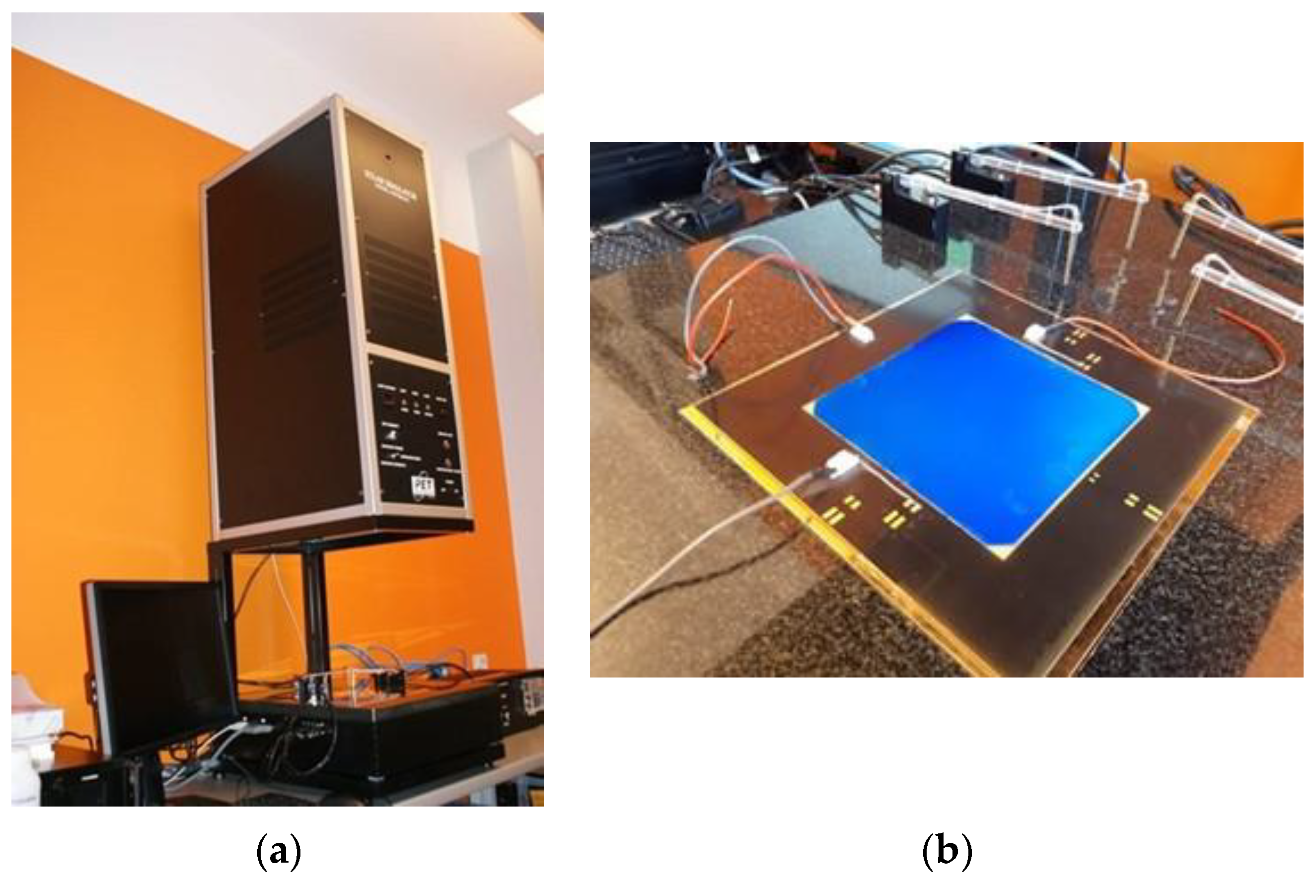
3.1. Test Stand for Collecting the Characteristics of Transmission, Absorption, and Reflection
3.2. Microscale Characterization Method
3.3. Test Stand for Collecting Current–Voltage Characteristics of a Solar Cell
4. Results and Discussion
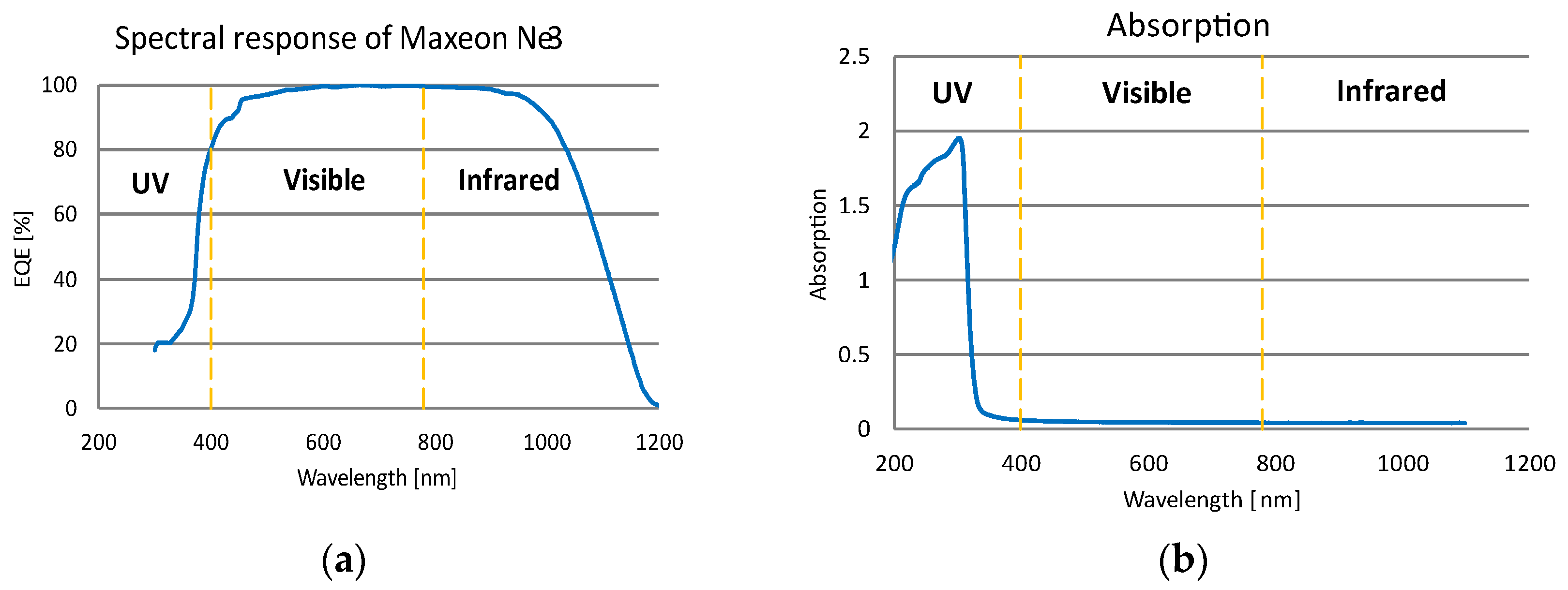
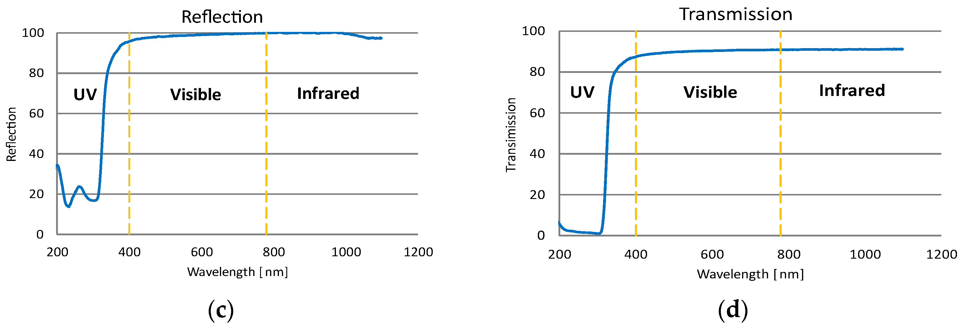
4.1. Transmission, Absorption, and Reflection of the Film
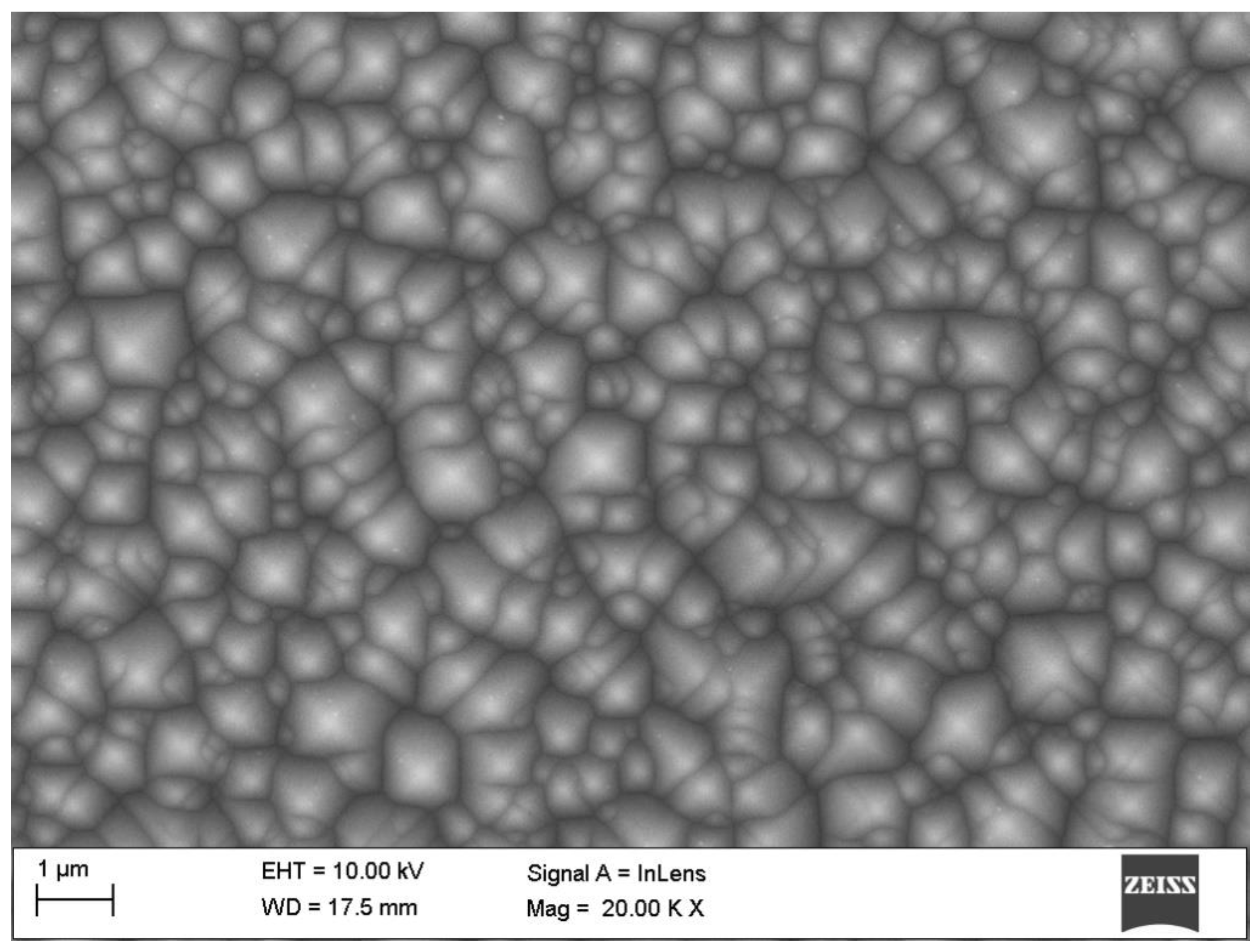
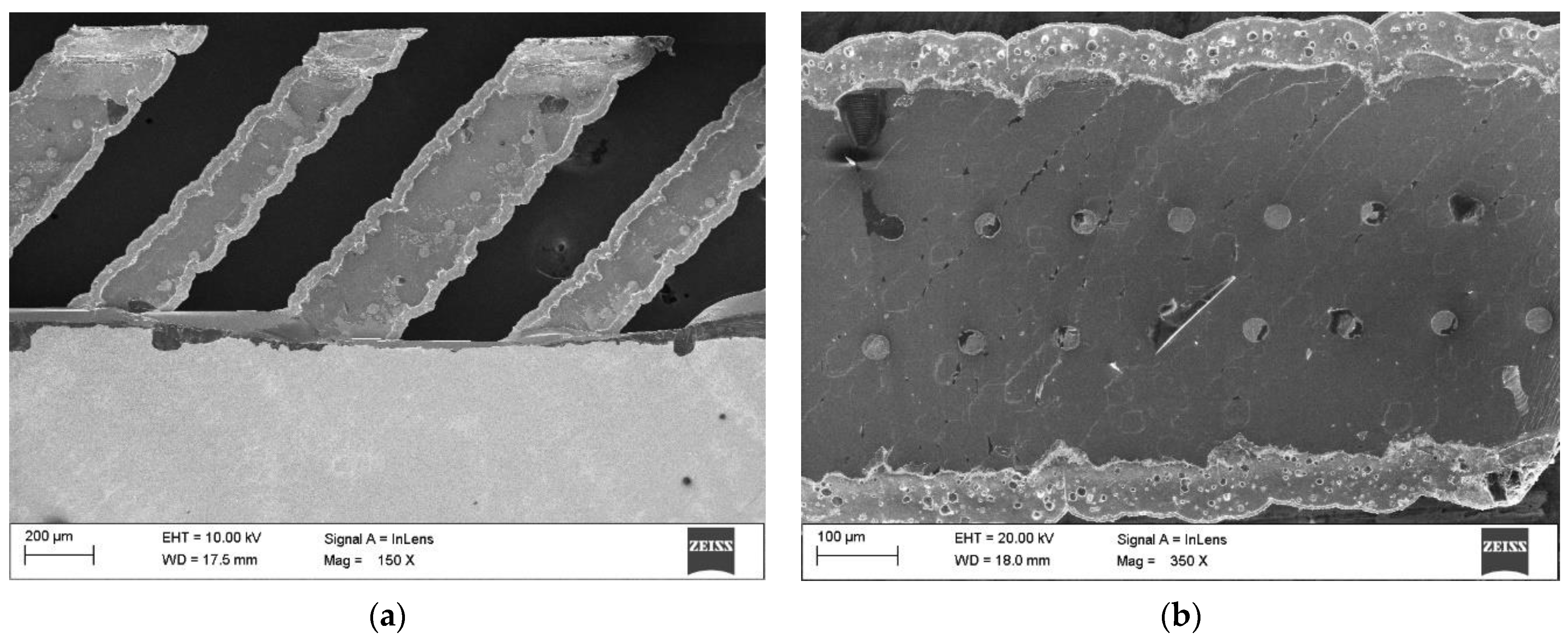
4.2. Microscopic Scale Observations of the Solar Cell
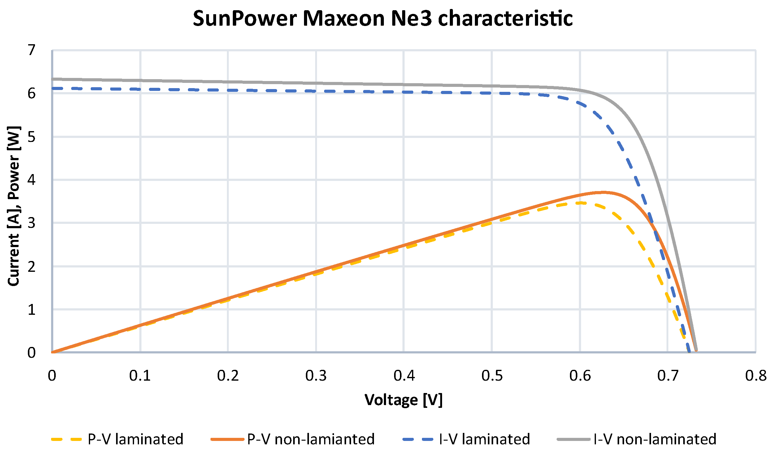
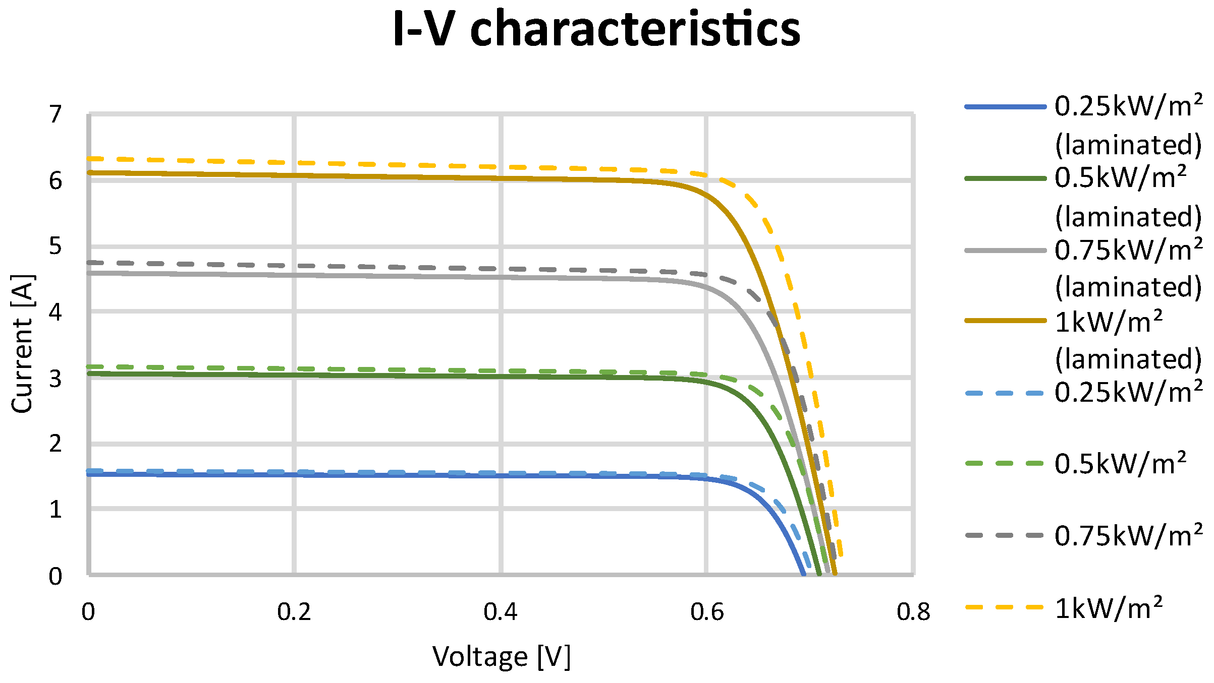
4.3. Solar Cell Characteristics
5. Conclusions
Author Contributions
Funding
Institutional Review Board Statement
Informed Consent Statement
Data Availability Statement
Acknowledgments
Conflicts of Interest
Abbreviations
| AM | Air mass |
| EVA | Ethylene–vinyl acetate |
| GaAs | Gallium arsenide |
| I-V | Current–voltage |
| IR | Infrared |
| P-V | Power–voltage |
| PV | Photovoltaics |
| PVC | Polyvinyl chloride |
| RSD | Relative standard deviation |
| STC | Standard test conditions |
| TS | TwinStratos |
| UAV | Unmanned aerial vehicle |
| UV | Ultraviolet |
References
- McEvoy, A.; Markvart, T.; Castañer, L. Practical Handbook of Photovoltaics Fundamentals and Applications, 2nd ed.; Elsevier: Waltham, MA, USA, 2011. [Google Scholar]
- Zhang, J.; Lou, M.; Xiang, L.; Hu, L. Power cognition: Enabling intelligent energy harvesting and resource allocation for solar-powered UAVs. Future Gener. Comput. Syst. 2020, 110, 658–664. [Google Scholar] [CrossRef]
- Bakar, A.; Ke, L.; Liu, H.; Xu, Z.; Wen, D. Design of Low Altitude Long Endurance Solar-Powered UAV Using Genetic Algorithm. Aerospace 2021, 8, 228. [Google Scholar] [CrossRef]
- Rydh, C.J.; Sandén, B.A. Energy analysis of batteries in photovoltaic systems. Part I: Performance and energy requirements. Energy Convers. Manag. 2005, 46, 1957–1979. [Google Scholar] [CrossRef]
- Rydh, C.J.; Sandén, B.A. Energy analysis of batteries in photovoltaic systems Part II: Energy return factors and overall battery efficiencies. Energy Convers. Manag. 2005, 46, 1980–2000. [Google Scholar] [CrossRef]
- Doskocz, J.; Kardasz, P.; Hejduk, M.; Wiejkut, P. The possibilities of using drones in the courier services. World Sci. News 2016, 48, 119–132. [Google Scholar]
- Papež, N.; Dallaev, R.; Ţălu, Ş.; Kaštyl, J. Overview of the Current State of Gallium Arsenide-Based Solar Cells. Materials 2021, 14, 3075. [Google Scholar] [CrossRef] [PubMed]
- Oettershagen, P.; Melzer, A.; Mantel, T.; Rudin, K.; Lotz, R.; Siebenmann, D. A Solar-Powered Hand-Launchable UAV for Low-Altitude Multi-Day Continuous Flight. In Proceedings of the IEEE International Conference on Robotics and Automation (ICRA), Seattle, WA, USA, 26–30 May 2015; pp. 3986–3993. [Google Scholar]
- Aktaş, A.; Kirçiçek, Y. Solar Hybrid Systems: Chapter 13—Examples of Solar Hybrid System Layouts, Design Guidelines, Energy Performance, Economic Concern, and Life Cycle Analyses; Elsevier: San Diego, CA, USA, 2021; pp. 331–349. [Google Scholar]
- Kalogirou, S.A. Solar Energy Engineering; Academic Press: Cambridge, MA, USA, 2009. [Google Scholar]
- Qazi, S. Standalone Photovoltaic (PV) Systems for Disaster Relief and Remote Areas: Chapter 7—Solar Thermal Electricity and Solar Insolation; Elsevier: Amsterdam, The Netherlands, 2017; pp. 203–237. [Google Scholar]
- Li, J.; Aierken, A.; Zhuang, Y.; Xu, P.Q.; Wu, H.Q.; Zhang, Q.Y.; Wang, X.B.; Mo, J.H.; Yang, X.; Chen, Q.Y.; et al. 1 MeV electron and 10 MeV proton irradiation effects on inverted metamorphic GaInP/GaAs/InGaAs triple junction solar cell. Sol. Energy Mater. Sol. Cells 2021, 224, 111022. [Google Scholar] [CrossRef]
- Singh, A. SunPower: A Path toward Strategic Development. Emerg. Econ. Cases J. 2021, 3, 77–86. [Google Scholar] [CrossRef]
- Omazic, A.; Oreski, G.; Halwachs, M.; Eder, G.C.; Hirschl, C.; Neumaier, L.; Pinter, G.; Erceg, M. Relation between degradation of polymeric components in crystalline silicon PV module and climatic conditions: A literature review. Sol. Energy Mater. Sol. Cells 2019, 192, 123–133. [Google Scholar] [CrossRef]
- Xue, B.; Li, F.; Song, M.; Shang, X.; Cui, D.; Chu, J.; Dai, S. Crack Extraction for Polycrystalline Solar Panels. Energies 2021, 14, 374. [Google Scholar] [CrossRef]
- Blakers, A.W.; Armour, T. Flexible silicon solar cells. Sol. Energy Mater. Sol. Cells 2009, 93, 1440–1443. [Google Scholar] [CrossRef]
- Li, X.; Li, P.; Wu, Z.; Luo, D.; Yu, H.Y.; Lu, Z.H. Review and perspective of materials for flexible solar cells. Mater. Rep. Energy 2021, 1, 100001. [Google Scholar] [CrossRef]
- Kim, S.; Hoang, V.Q.; Bark, C.W. Silicon-Based Technologies for Flexible Photovoltaic (PV) Devices: From Basic Mechanism to Manufacturing Technologies. Nanomaterials 2021, 11, 2944. [Google Scholar] [CrossRef] [PubMed]
- Oettershagen, P.; Melzer, A.; Mantel, T.; Rudin, K.; Stastny, T.; Wawrzacz, B.; Hinzmann, T.; Leutenegger, S.; Alexis, K.; Siegwart, R. Design of small hand-launched solar-powered UAVs: From concept study to a multi-day world endurance record flight. J. Field Robot. 2017, 34, 1352–1377. [Google Scholar] [CrossRef]
- Kokkos, S.; Morfidis, E. Aerodynamic Design and Analysis of Solar Powered UAV (Unmanned Aerial Vehicle). Master’s Thesis, University of Thessaly, Volos, Greece, 2020. [Google Scholar]
- Fegade, U.A.; Jethave, G.N. Interface Science and Technology, Chapter 15—Photocatalytic Reduction of CO2 in Hydrocarbon: A Greener Approach for Energy Production; Elsevier: Amsterdam, The Netherlands, 2021; pp. 871–915. [Google Scholar]
- Brochure: Evolution 201 and 220 UV-Visible Spectrophotometers. Available online: https://assets.thermofisher.com/TFS-Assets%2FMSD%2Fbrochures%2FBR51944-evolution-201-220.pdf (accessed on 29 September 2022).
- Liu, Y.; Xu, Z.; Du, H.; Lv, M. Multidisciplinary Optimization of Thermal Insulation Layer for Stratospheric Airship with a Solar Array. Aerospace 2022, 9, 83. [Google Scholar] [CrossRef]
- Feister, U.; Cabrol, N.; Häder, D. UV Irradiance Enhancements by Scattering of Solar Radiation from Clouds. Atmosphere 2015, 6, 1211–1228. [Google Scholar] [CrossRef]
- Brizon, M. Solar Energy Generation Model for High Altitude Long Endurance Platforms. Master’s Thesis, KTH—Royal Institute of Technology, Stockholm, Sweden, 2016. [Google Scholar]
- Han, X.T.; Xie, A.Y.; Bi, X.C.; Liu, S.J.; Hu, L.H. Effects of altitude, ambient temperature and solar radiation on fasting heat production in yellow cattle (Bos taurus). Br. J. Nutr. 2003, 89, 399–408. [Google Scholar] [CrossRef]
- Semenova, O.V.; Yuzova, V.A.; Patrusheva, T.N.; Merkushev, F.F.; Railko, M.Y.; Podorozhnyak, S.A. Antireflection and protective films for silicon solar cells. In Proceedings of the IOP Conference Series Materials Science and Engineering, Tomsk, Russia, 14–18 April 2014. [Google Scholar]
- Swatowska, B.; Stapinski, T.; Drabczyk, K.; Panek, P. The role of antireflective coatings in silicon solar cells—The influence on their electrical parameters. Opt. Appl. 2011, 41, 487–492. [Google Scholar]
- Microfractures in Solar Modules: Causes, Detection and Consequences. GSES Technical Papers. Available online: https://www.gses.com.au/wp-content/uploads/2016/03/GSES_microfractures.pdf (accessed on 29 September 2022).
- Tsach, S.; Ankri, L.; Cohen, M.; Ehrlich, Y.; Goldenberg, T.; Levy, H.; Regev, I.; Vladimirsky, A.; Weider, A.; Yossef, Z. Sunsailor: Solar Powered UAV. In Proceedings of the 47th Israel Annual Conference on Aerospace Sciences, Tel Aviv, Israel, 21–22 February 2007. [Google Scholar]
- Sousa, J.C. Solar System for a Long Endurance Electric UAV. Master’s Thesis, University of Beira Interior, Covellian, Portugal, 2015. [Google Scholar]
- Oettershagen, P. Solar-Powered Unmanned Aerial Vehicles: Design and Environment-Aware Navigation for Robust Low-Altitude Multi-Day Continuous Flight. Doctor Thesis, ETH Zurich, Zurich, Switzerland, 2018. [Google Scholar]
- Energy to Cross Oceans and Continents. Available online: https://aroundtheworld.solarimpulse.com/adventure (accessed on 15 June 2022).
- Polymers Aiding Solar Impulse 2′s Round-the-World Adventure. Available online: https://knowledge.ulprospector.com/4541/polymers-aiding-solar-impulse-2s-round-world-adventure/ (accessed on 15 June 2022).
- Mateja, K.; Skarka, W. Towards energetic autonomy of UAV. In Proceedings of the 27th ISTE International Conference on Transdisciplinary Engineering, Warsaw, Poland, 1–10 July 2020; pp. 423–432. [Google Scholar]
- Zenowicz, K.; Skarka, W. Verification of Flutter Method for the Purposes of Building a Very Flexible Wing Generative Model. In Proceedings of the 27th ISTE International Conference on Transdisciplinary Engineering, Warsaw, Poland, 1–10 July 2020; pp. 383–392. [Google Scholar]
- Skarka, W.; Jałowiecki, A. Automation of a Thin-Layer Load-Bearing Structure Design on the Example of High Altitude Long Endurance Unmanned Aerial Vehicle (HALE UAV). Appl. Sci. 2021, 11, 2645. [Google Scholar] [CrossRef]
- Datasheet SunPower Maxeon Ne3. Available online: https://www.makeyoursolar.com/ (accessed on 29 September 2022).
- Targosz, M.; Skarka, W.; Przystałka, P. Model-based optimization of velocity strategy for lightweight electric racing cars. J. Adv. Transp. 2018, 2018, 3614025. [Google Scholar] [CrossRef]
- Niestrój, R.; Rogala, T.; Skarka, W. An Energy Consumption Model for Designing an AGV Energy Storage System with a PEMFC Stack. Energies 2020, 13, 3435. [Google Scholar] [CrossRef]
- Peciak, M.; Skarka, W. Assessment of the Potential of Electric Propulsion for General Aviation Using Model-Based System Engineering (MBSE) Methodology. Aerospace 2022, 9, 74. [Google Scholar] [CrossRef]
- Dwivedi, V.S.; Patrikar, J.; Addamane, A.; Ghosh, A.K. MARAAL: A Low Altitude Long Endurance Solar Powered UAV for Surveillance and Mapping Applications. In Proceedings of the 23rd International Conference on Methods & Models in Automation & Robotics (MMAR), Miedzyzdroje, Poland, 27–30 August 2018; pp. 449–454. [Google Scholar] [CrossRef]
- Sisanth, K.S.; Thomas, M.G.; Abraham, J.; Thomas, S. General Introduction to Rubber Compounding. In Progress in Rubber Nanocomposites; Elsevier: Amsterdam, The Netherlands, 2017; pp. 1–39. ISBN 978-0-08-100409-8. [Google Scholar]
- IEC 60904-3; Photovoltaic Devices—Part 3: Measurement Principles for Terrestrial Photovoltaic (PV) Solar Devices with Reference Spectral Irradiance Data. IEC: Geneva, Switzerland, 2019.
- IEC 60904-1; Photovoltaic Devices—Part 1: Measurement of PV Current-Voltage Characteristics. IEC: Geneva, Switzerland, 2019.
- Leitão, D.; Torres, J.P.N.; Fernandes, J.F.P. Spectral Irradiance Influence on Solar Cells Efficiency. Energies 2020, 13, 5017. [Google Scholar] [CrossRef]
- Sankarasubramaniam, S.; Saud, G.K.; Shashikala, M.; Suratkar, P.; Saravanan, S. Impact of surface texturization on overall performance of mono-crystalline silicon solar cells. ECS Trans. 2015, 66, 9–17. [Google Scholar] [CrossRef]
- Dobrzański, L.A.; Drygała, A. Laser application in photovoltaics for surface texturization of silicon and front electrode deposition. Mater. Perform. Charact. 2019, 8, 1136–1146. [Google Scholar] [CrossRef]
- Kulesza-Matlak, G.; Gawlińska, K.; Starowicz, Z.; Sypień, A.; Drabczyk, K.; Drabczyk, B.; Lipiński, M.; Zięba, P. Black silicon obtained in two-step short wet etching as a texture for silicon solar cells—Surface microstructure and optical properties studies. Arch. Metall. Mater. 2018, 63, 1009–1017. [Google Scholar]


| Film Thickness (μm) | Effect |
|---|---|
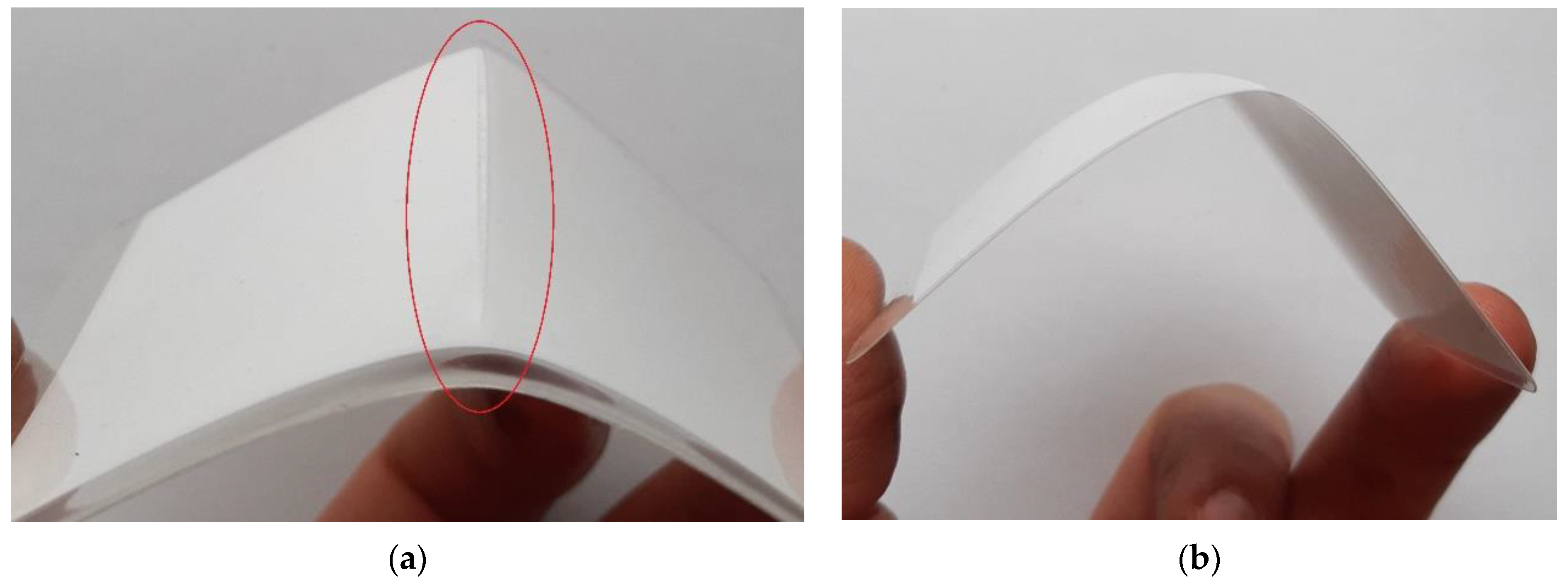
| ≤100 | The incision damaged the inner side of the film. Due to the high flexibility of the film, the incision did not enlarge. |
| 125–200 | The incision damaged the inside of the film, enlarging the gap due to prolonged bending. |
| ≥250 | The incision did not damage the inner side of the film. However, due to bending, the gap burst. |
| Film Thickness (μm) | Effect |
|---|---|
| <100 | In the case of thin film, the defect easily increased due to its delicate surface. |
| 100–200 | In the case of the intermediate films, the defect increased, but more slowly than in the case of thin and thick films. |
| ≥250 | In the case of thick films, the defect increased easily due to their greater brittleness/fragility. |
| Data | Manufacturer Data (Non-Laminated) | Non-Laminated | Laminated (100 μm Film) |
|---|---|---|---|
| Voc (V) | >0.731 | 0.733 | 0.726 |
| Isc (A) | >6.382 | 6.330 | 6.061 |
| Vmp (V) | >0.625 | 0.627 | 0.624 |
| Imp (A) | >6.050 | 5.92 | 5.747 |
| Pmpp (Wp) | >3.77 | 3.71 | 3.589 |
| Fill Factor (%) | 80.8 | 80.8 | 81 |
| Efficiency (%) | >24.34 | 24.29 | 23.33 |
| Data | Non-Laminated | Laminated (100 μm Film) | ||||
|---|---|---|---|---|---|---|
| Min | Max | RSD (%) | Min | Max | RSD (%) | |
| Voc (V) | 0.728 | 0.738 | 0.77 | 0.725 | 0.731 | 1.81 |
| Isc (A) | 6.109 | 6.33 | 0.28 | 6.032 | 6.421 | 0.24 |
| Vmp (V) | 0.616 | 0.639 | 1.04 | 0.604 | 0.629 | 1.47 |
| Imp (A) | 5.793 | 6.039 | 0.79 | 5.724 | 6.05 | 1.15 |
| Pmpp (Wp) | 3.619 | 3.82 | 1.32 | 3.51 | 3.7 | 1.27 |
| Fill Factor (%) | 79.9 | 84.2 | 1.23 | 77.1 | 82.2 | 1.9 |
| Efficiency (%) | 24 | 24.77 | 1.12 | 23.01 | 23.79 | 0.85 |
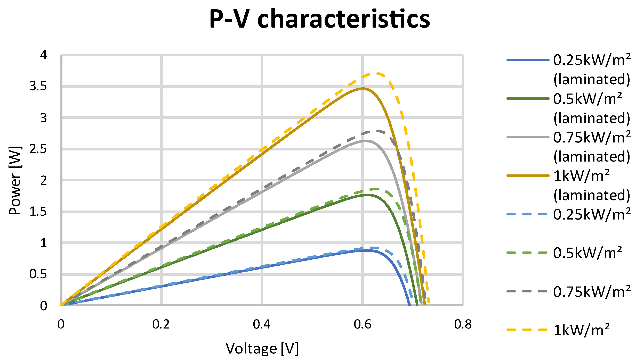
| Non-Laminated | ||||
| Irradiation (W/m2) | Voltage (V) | Current (A) | Power (W) | Fill Factor (%) |
| 1000 | 0.627 | 5.92 | 3.709 | 80.8 |
| 750 | 0.626 | 4.439 | 2.779 | 59.9 |
| 500 | 0.622 | 2.961 | 1.842 | 39.7 |
| 250 | 0.611 | 1.482 | 0.906 | 19.5 |
| Laminated | ||||
| Irradiation (W/m2) | Voltage (V) | Current (A) | Power (W) | Fill Factor (%) |
| 1000 | 0.624 | 5.748 | 3.588 | 81 |
| 750 | 0.622 | 4.317 | 2.684 | 61 |
| 500 | 0.618 | 2.872 | 1.776 | 40 |
| 250 | 0.606 | 1.437 | 0.871 | 19.8 |
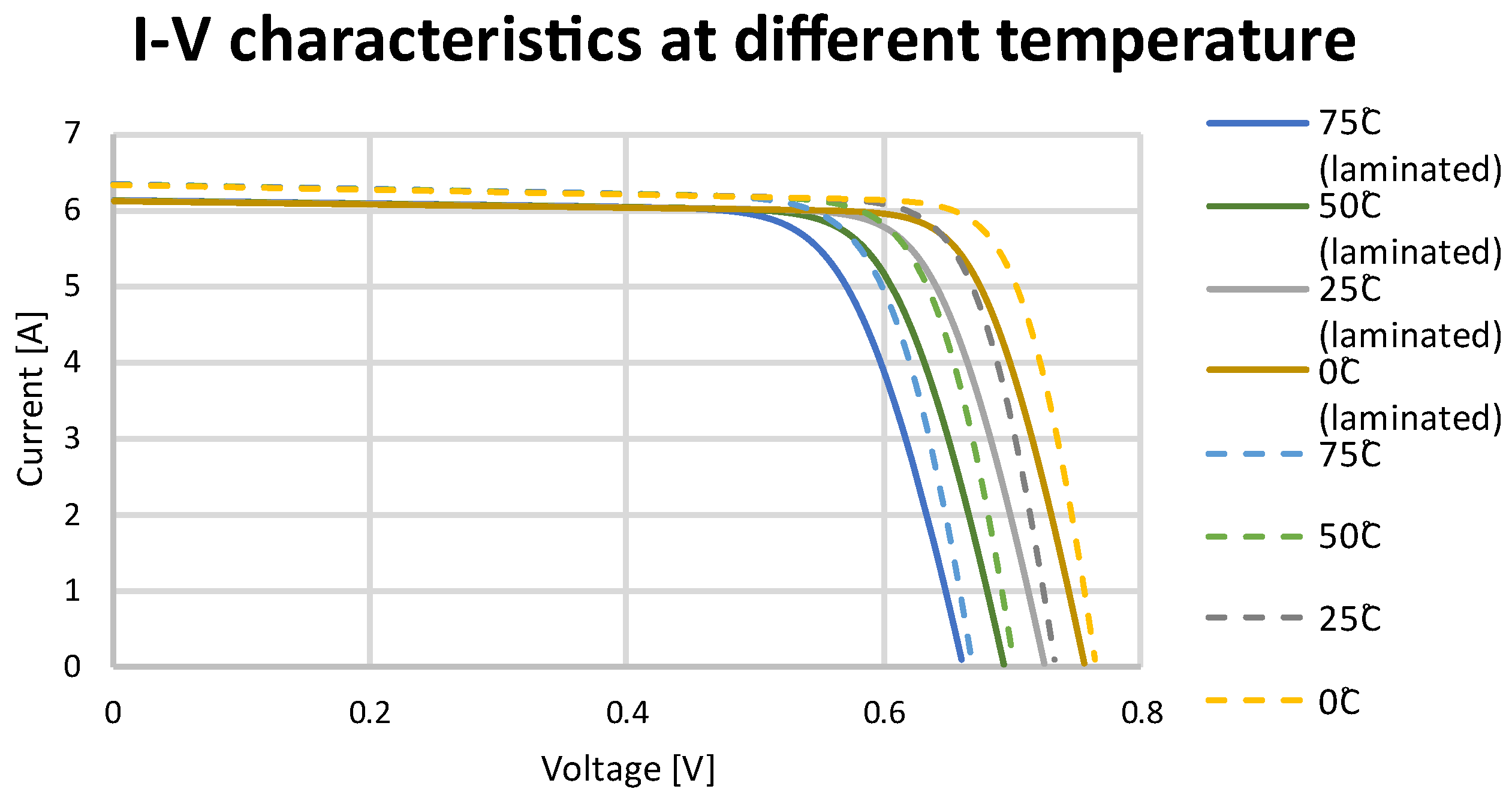
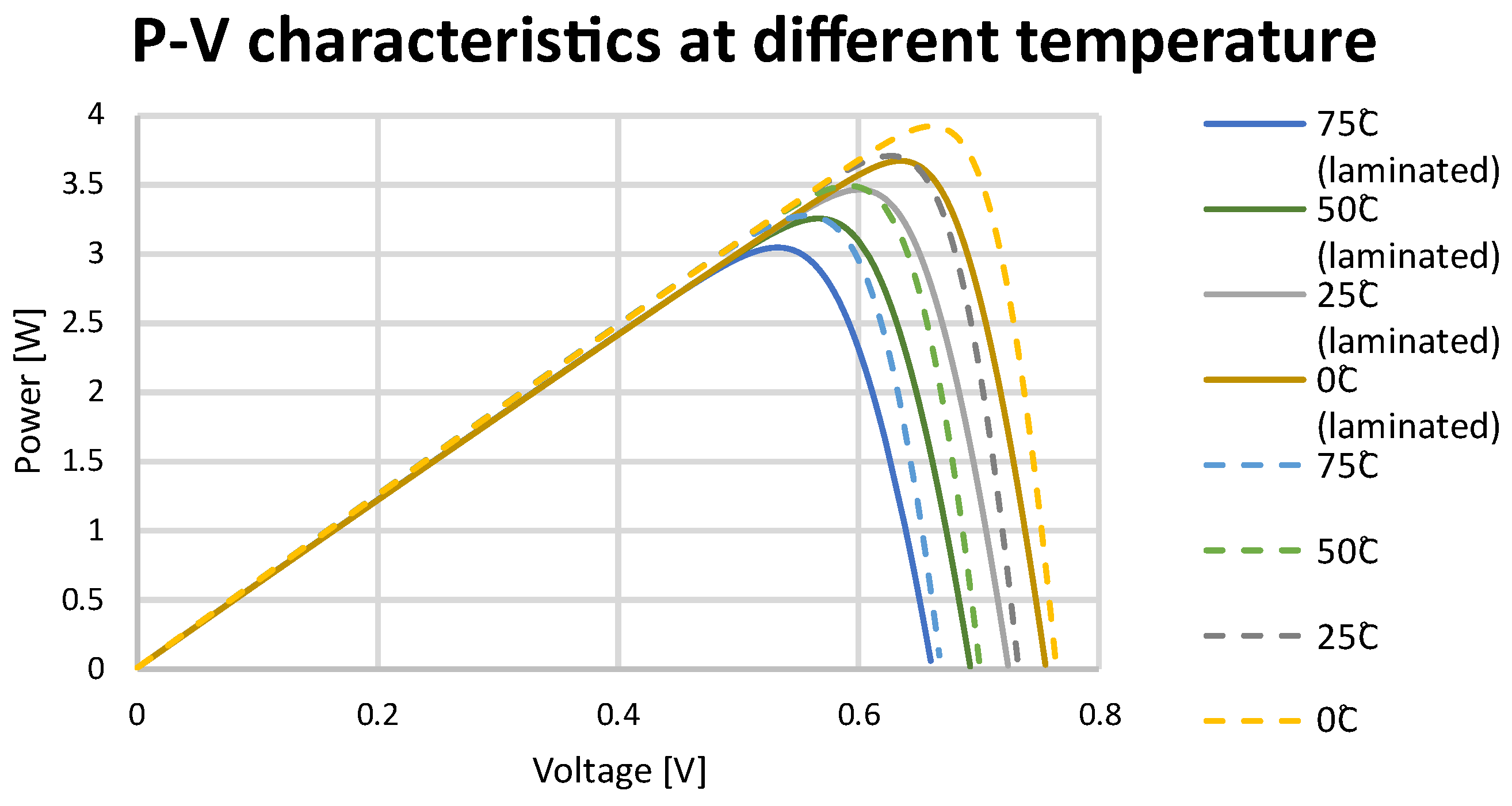
| Non-Laminated | ||||
| Temperature | Voltage (V) | Current (A) | Power (W) | Fill Factor (%) |
| 0 | 0.673 | 5.876 | 3.952 | 85.1 |
| 25 | 0.627 | 5.92 | 3.709 | 80.8 |
| 50 | 0.58 | 5.964 | 3.458 | 74.5 |
| 75 | 0.534 | 5.992 | 3.201 | 69 |
| Laminated | ||||
| Temperature | Voltage (V) | Current (A) | Power (W) | Fill Factor (%) |
| 0 | 0.671 | 5.706 | 3.827 | 87 |
| 25 | 0.624 | 5.748 | 3.588 | 81 |
| 50 | 0.578 | 5.779 | 3.343 | 76 |
| 75 | 0.532 | 5.813 | 3.092 | 70.2 |
Publisher’s Note: MDPI stays neutral with regard to jurisdictional claims in published maps and institutional affiliations. |
© 2022 by the authors. Licensee MDPI, Basel, Switzerland. This article is an open access article distributed under the terms and conditions of the Creative Commons Attribution (CC BY) license (https://creativecommons.org/licenses/by/4.0/).
Share and Cite
Mateja, K.; Skarka, W.; Drygała, A. Efficiency Decreases in a Laminated Solar Cell Developed for a UAV. Materials 2022, 15, 8774. https://doi.org/10.3390/ma15248774
Mateja K, Skarka W, Drygała A. Efficiency Decreases in a Laminated Solar Cell Developed for a UAV. Materials. 2022; 15(24):8774. https://doi.org/10.3390/ma15248774
Chicago/Turabian StyleMateja, Krzysztof, Wojciech Skarka, and Aleksandra Drygała. 2022. "Efficiency Decreases in a Laminated Solar Cell Developed for a UAV" Materials 15, no. 24: 8774. https://doi.org/10.3390/ma15248774
APA StyleMateja, K., Skarka, W., & Drygała, A. (2022). Efficiency Decreases in a Laminated Solar Cell Developed for a UAV. Materials, 15(24), 8774. https://doi.org/10.3390/ma15248774