
Experimental and Numerical Study of Thermal Residual Stresses on Multimaterial Adherends in Single-Lap Joints

 ,
,  ,
, 
Abstract
1. Introduction
2. Experimental Details
2.1. Materials
2.1.1. Adhesive
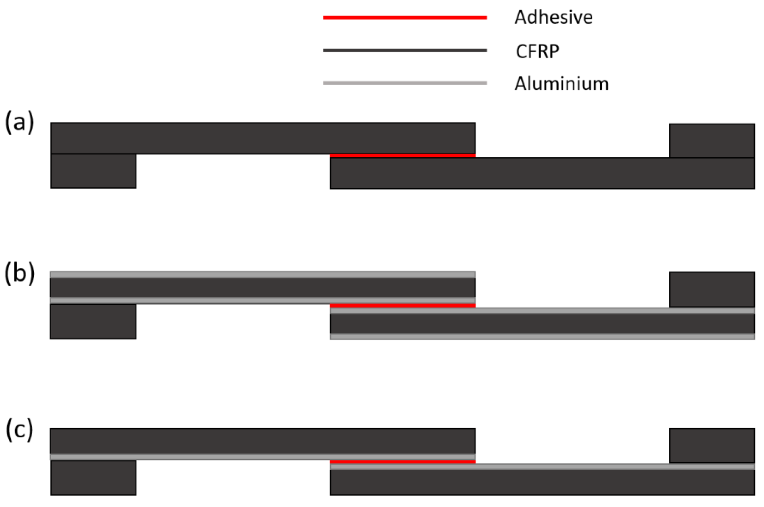
2.1.2. Adherend
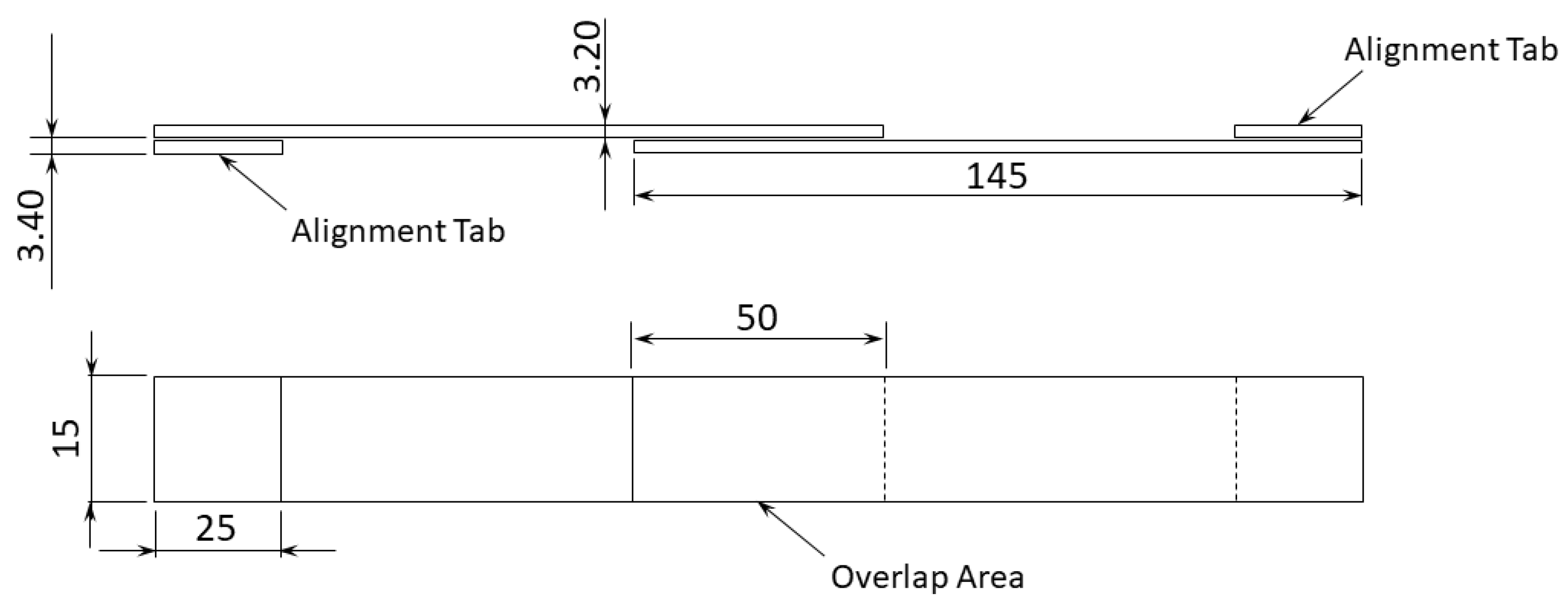
2.2. SLJ Specimen Manufacturing
2.3. Testing Setup
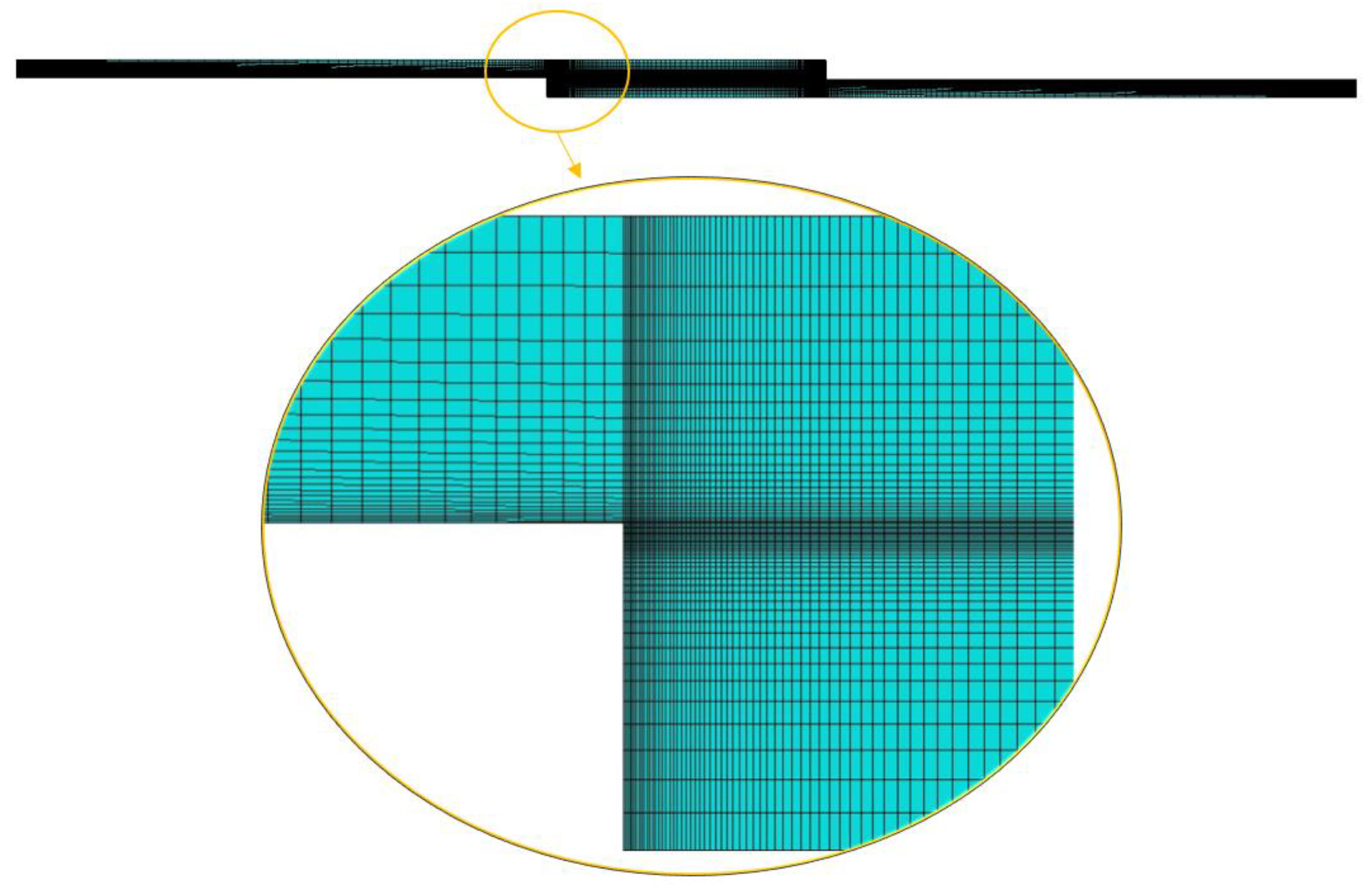
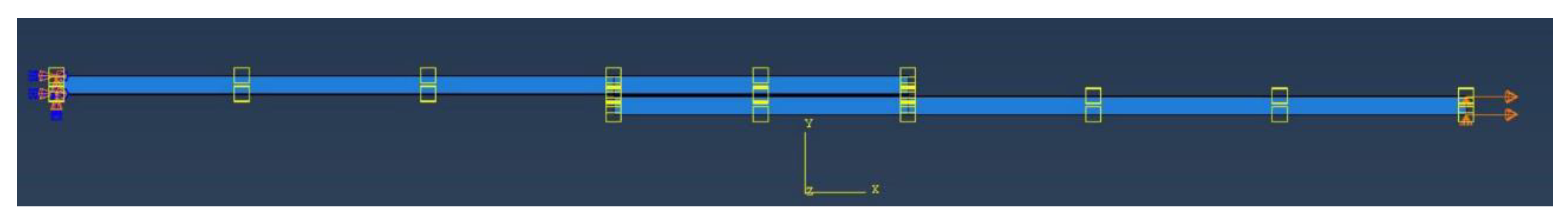
3. Numerical Details
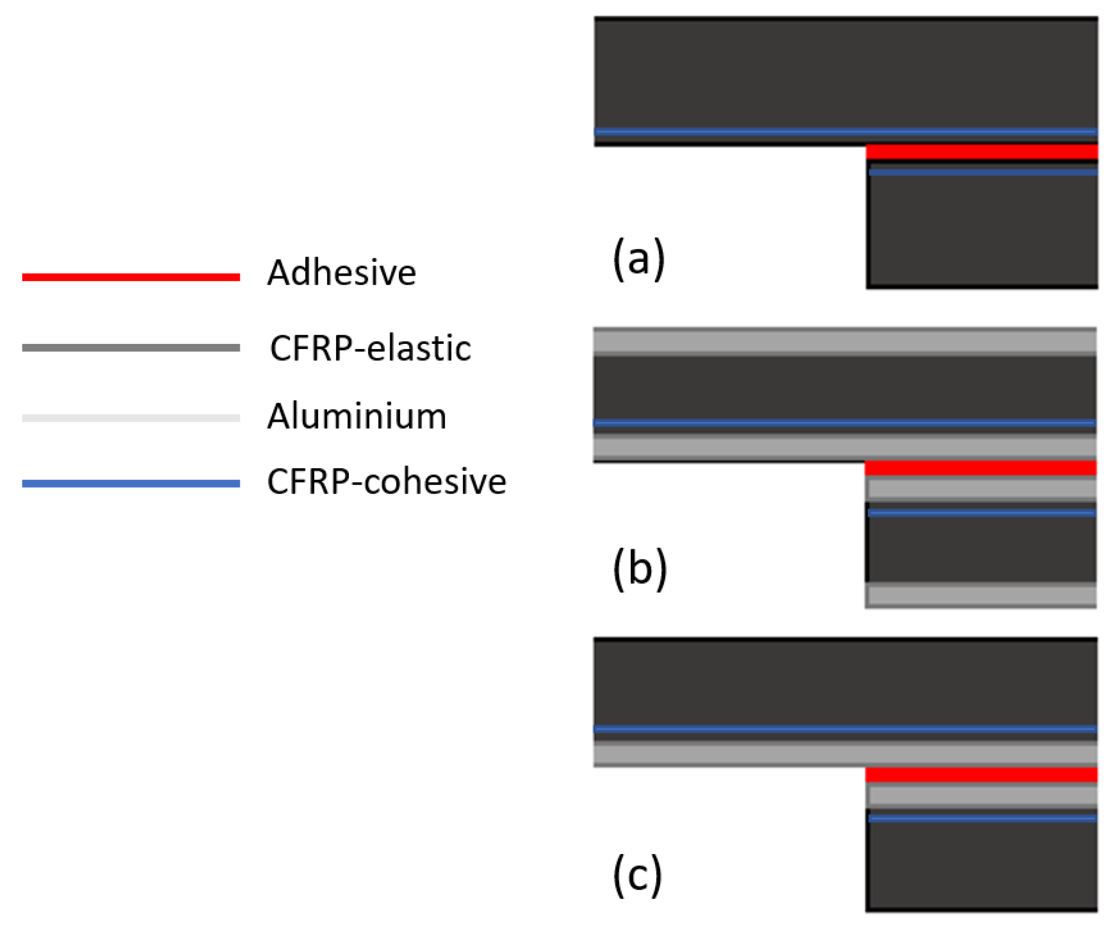
3.1. Elastic Model
3.2. CZM Model
4. Results and Discussion
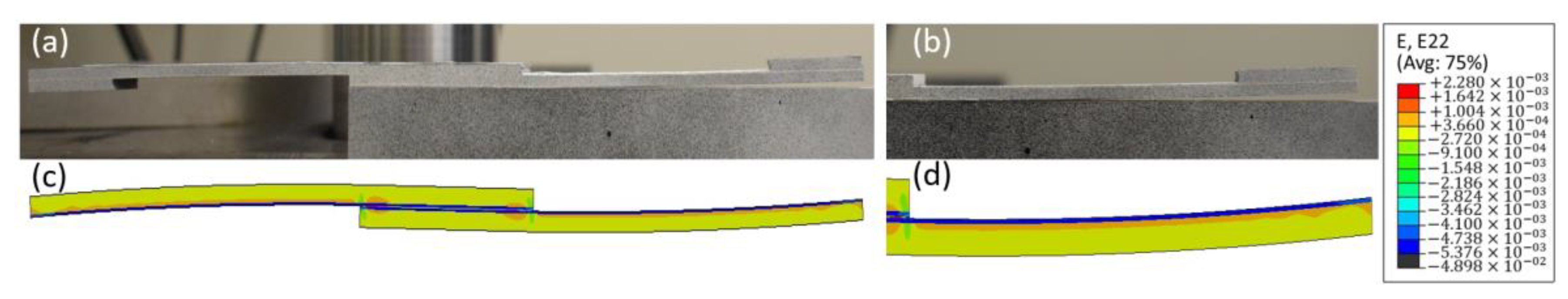
4.1. Deflection after Curing
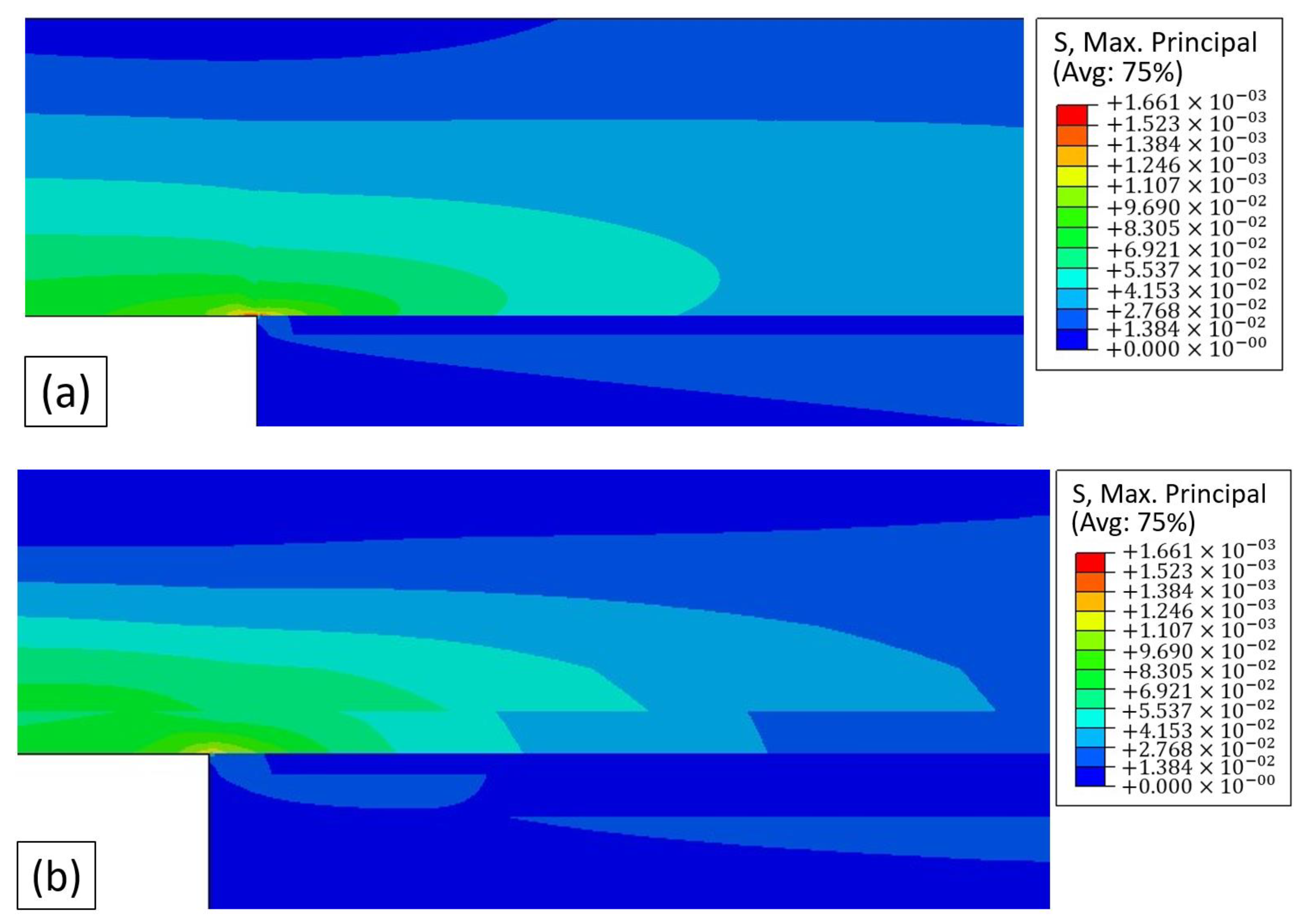
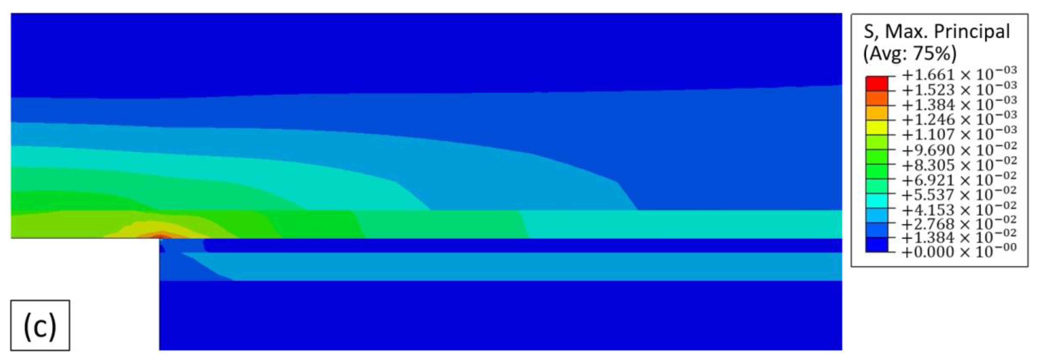
4.2. Elastic Modelling Analysis
4.3. SLJ Results
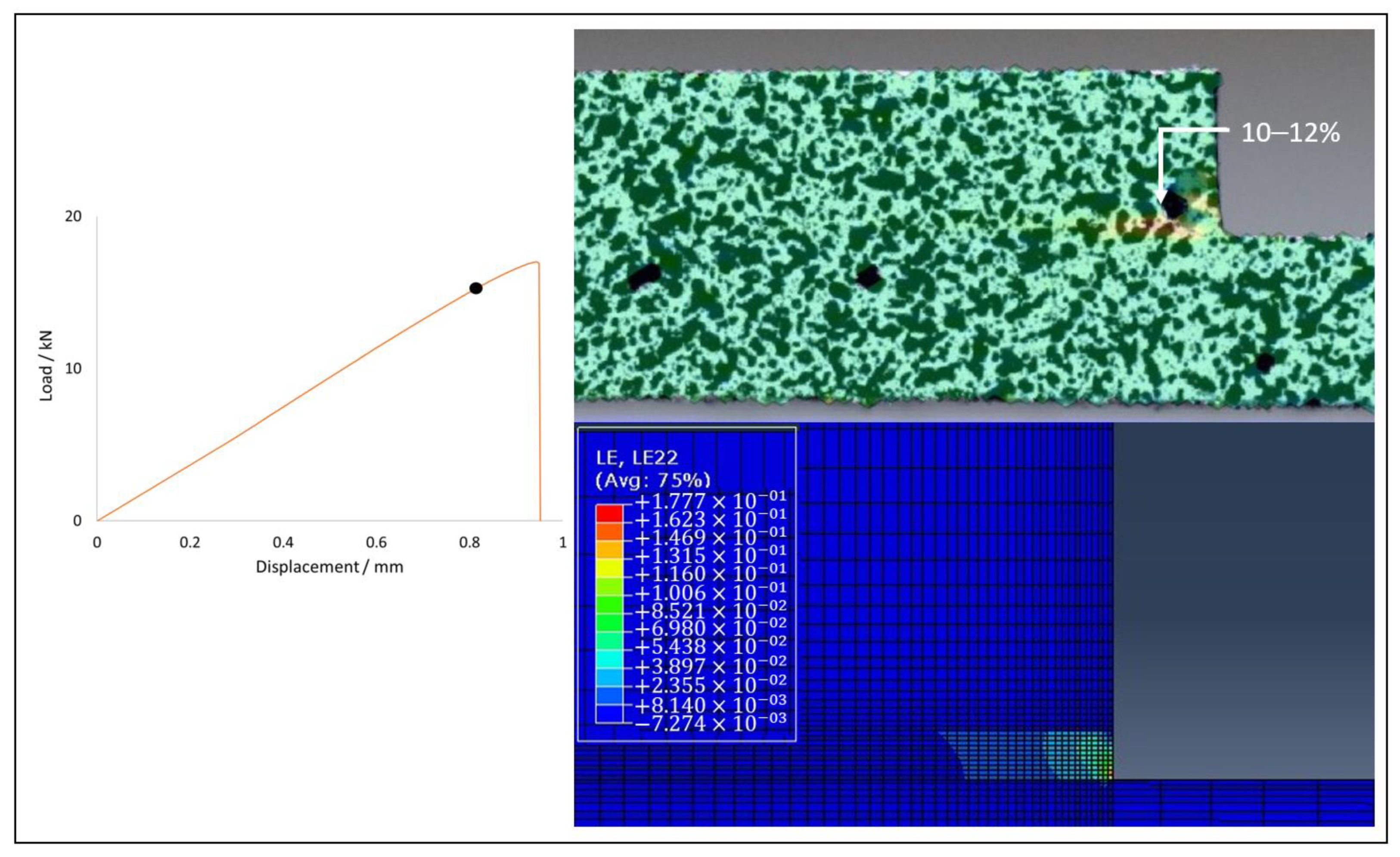
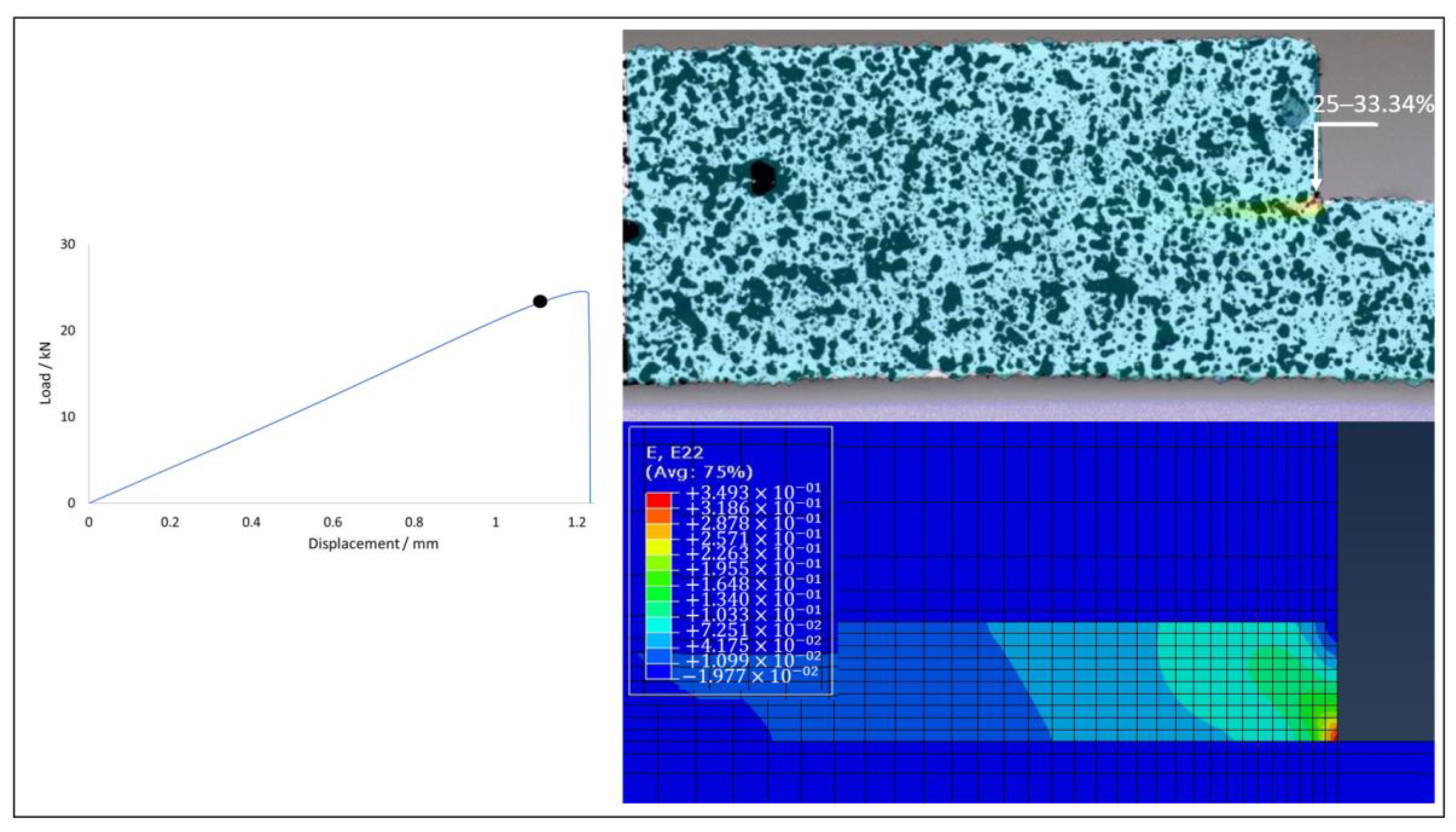
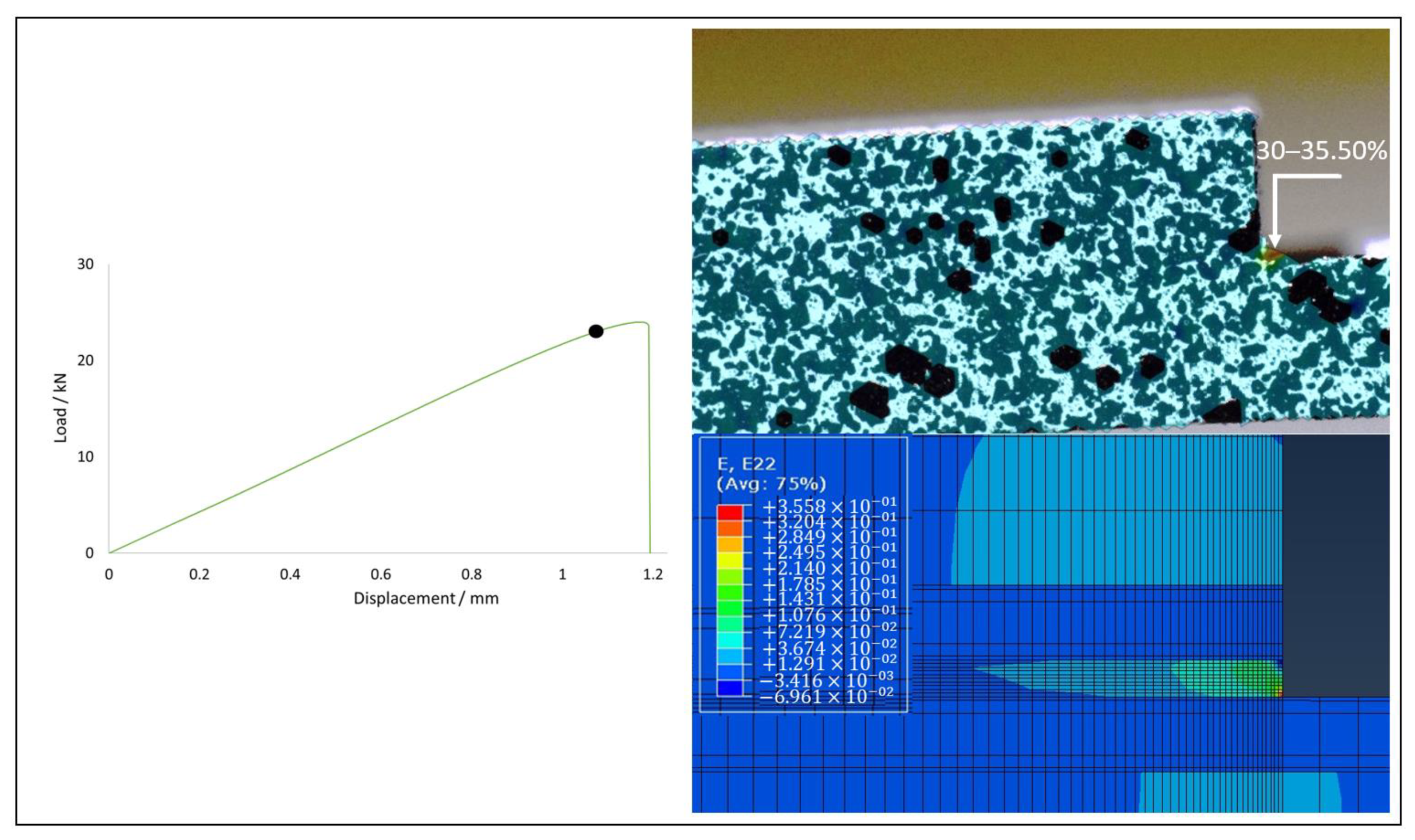
Failure Mechanism Analysis
5. Conclusions
- The CFRP-Al specimens showed a large deviation from its initial geometry after curing, which may be unacceptable for larger and more complex geometries. However, the controlled use of these deformations, adapted to each application, may prove to be advantageous.
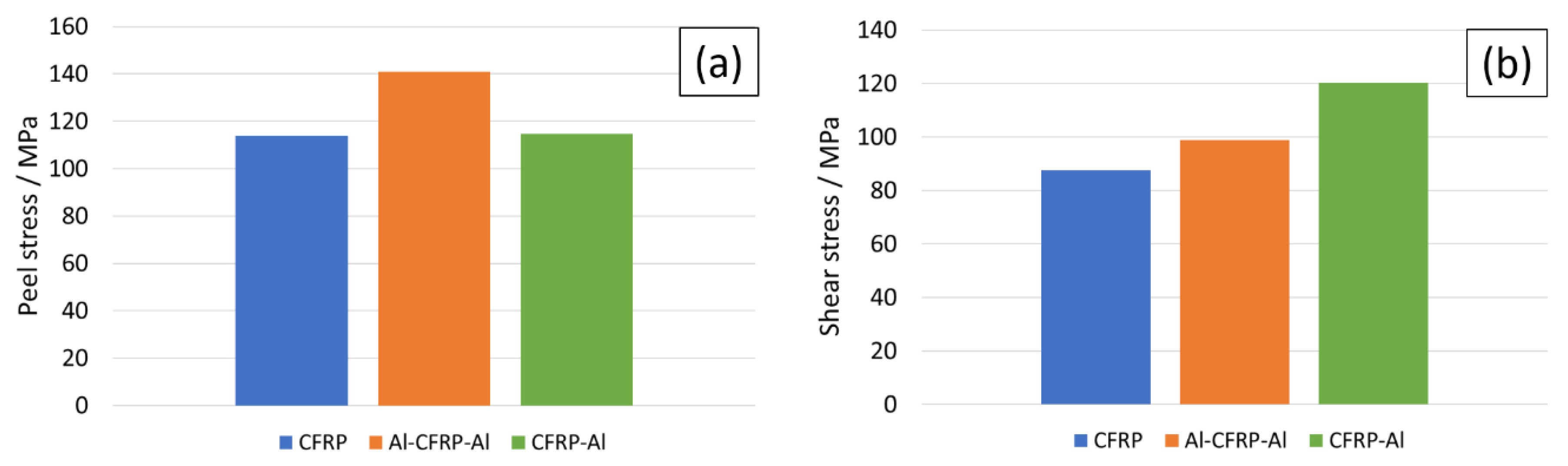
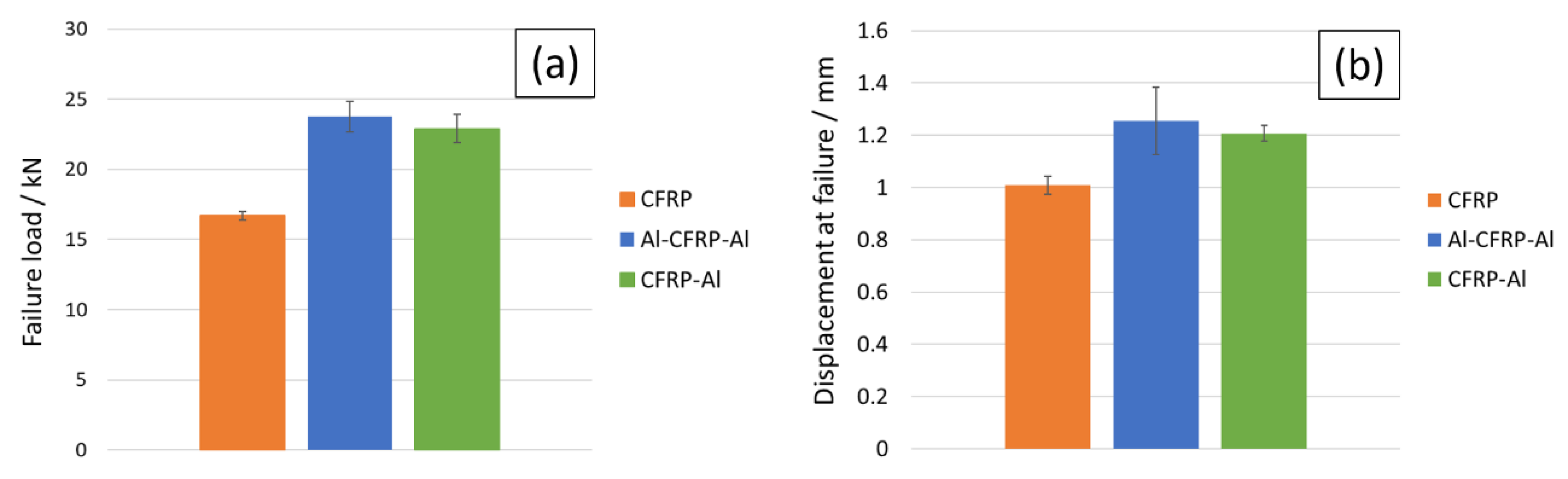
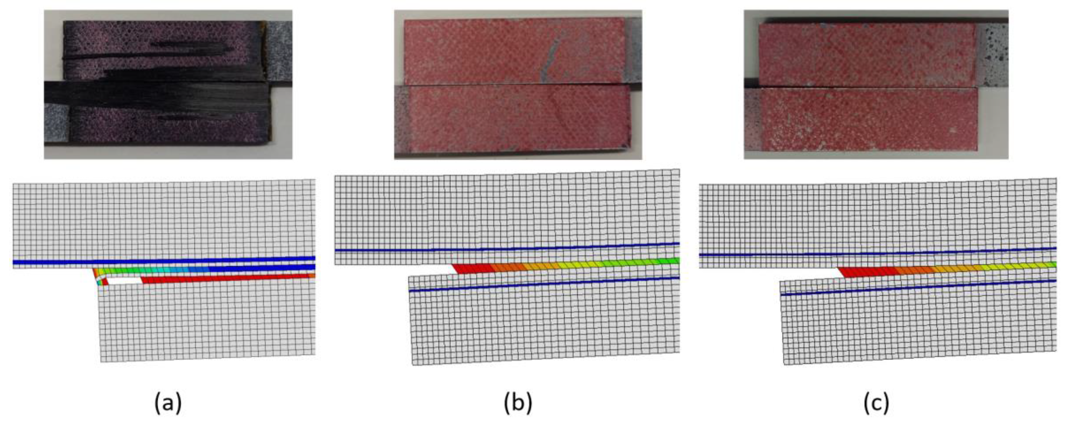
- The values obtained for joint strength showed that the smoother stress distribution achieved by the introduction of aluminium layers has a positive influence on the performance of composite joints. These layers were found to be able to avoid failure by delamination and to increase joint strength by more than 35%.
- Although both FML configurations exhibited similar performance, both in joint strength and failure mode, the CFRP-Al solution presented the highest specific strength. This is of importance since these materials are to be used in the aeronautical and aerospace industries, where high specific strength is imperative.
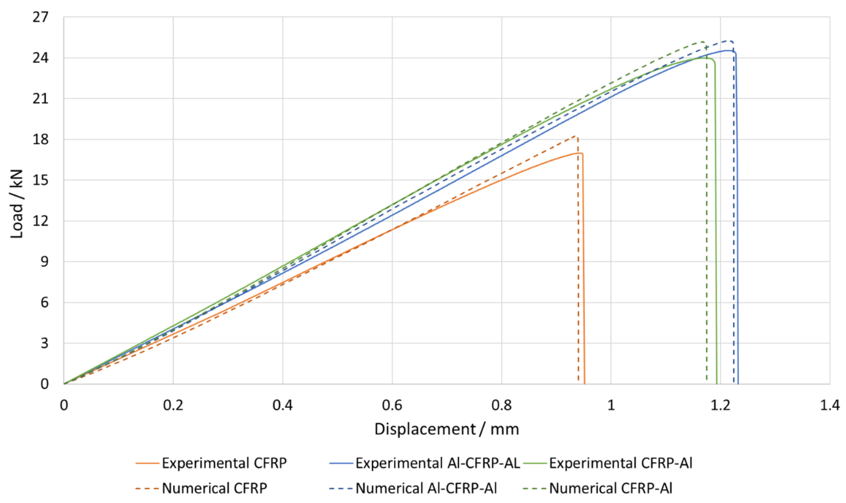
- All numerical models presented good correlation with the experimental results. For all joints, the numerically determined failure load values were generally close to the experimentally determined values.
- The failure modes obtained experimentally were also correctly reproduced by the models.
Author Contributions
Funding
Conflicts of Interest
References
- Yi, X.; Du, S.; Zhang, L. Composite Materials Engineering, Volume 1: Fundamentals of Composite Materials; Springer: Berlin/Heidelberg, Germany, 2018. [Google Scholar]
- Banea, M.D.; Rosioara, M.; Carbas, R.J.C.; da Silva, L.F.M. Multi-material adhesive joints for automotive industry. Compos. Part B Eng. 2018, 151, 71–77. [Google Scholar] [CrossRef]
- Nicolais, L.; Meo, M.; Milella, E. Composite Materials: A Vision for the Future; Springer: Berlin/Heidelberg, Germany, 2011. [Google Scholar]
- Hader-Kregl, L.; Wallner, G.M.; Kralovec, C.; Eyßell, C. Effect of inter-plies on the short beam shear delamination of steel/composite hybrid laminates. J. Adhes. 2019, 95, 1088–1100. [Google Scholar] [CrossRef]
- Kötter, B.; Yamada, K.; Körbelin, J.; Kawabe, K.; Nishikawa, M.; Hojo, M.; Fiedler, B. Steel foil reinforcement for high performance bearing strength in Thin-Ply composites. Compos. Part C Open Access 2021, 4, 100085. [Google Scholar] [CrossRef]
- Ramezani, F.; Nunes, P.D.P.; Carbas, R.J.C.; Marques, E.A.S.; da Silva, L.F.M. The joint strength of hybrid composite joints reinforced with different laminates materials. J. Adv. Join. Process. 2022, 5, 100103. [Google Scholar] [CrossRef]
- Kupski, J.; Teixeira de Freitas, S. Design of adhesively bonded lap joints with laminated CFRP adherends: Review, challenges and new opportunities for aerospace structures. Compos. Struct. 2021, 268, 113923. [Google Scholar] [CrossRef]
- Shang, X.; Marques, E.A.S.; Machado, J.J.M.; Carbas, R.J.C.; Jiang, D.; da Silva, L.F.M. A strategy to reduce delamination of adhesive joints with composite substrates. Proc. Inst. Mech. Eng. Part L J. Mater. Des. Appl. 2018, 233, 521–530. [Google Scholar] [CrossRef]
- Shang, X.; Marques, E.A.S.; Machado, J.J.M.; Carbas, R.J.C.; Jiang, D.; da Silva, L.F.M. Review on techniques to improve the strength of adhesive joints with composite adherends. Compos. Part B Eng. 2019, 177, 107363. [Google Scholar] [CrossRef]
- Kanani, A.Y.; Hou, X.; Ye, J. A novel dissimilar single-lap joint with interfacial stiffness improvement. Compos. Struct. 2020, 252, 112741. [Google Scholar] [CrossRef]
- Xu, P.; Zhou, Z.; Liu, T.; Mal, A. Determination of geometric role and damage assessment in hybrid fiber metal laminate (FML) joints based on acoustic emission. Compos. Struct. 2021, 270, 114068. [Google Scholar] [CrossRef]
- Kumar, S.A.; Rajesh, R.; Pugazhendhi, S. A review of stress concentration studies on fibre composite panels with holes/cutouts. Proc. Inst. Mech. Eng. Part L J. Mater. Des. Appl. 2020, 234, 1461–1472. [Google Scholar] [CrossRef]
- Mottaghian, F.; Taheri, F. On the flexural response of nanoparticle-reinforced adhesively bonded joints mating 3D-Fiber Metal Laminates—A coupled numerical and experimental investigation. Int. J. Adhes. Adhes. 2022, in press. [CrossRef]
- Barzey, C.E.; Reichard, R.P. Investigating the mechanical performance of advanced marine coatings used for bonding composites to aluminum in-mold. J. Adhes. 2022, 98, 2094–2117. [Google Scholar] [CrossRef]
- Astigarraga, V.; Gondra, K.; Valea, Á.; Pardo Aurrekoetxea, G. Improvement of adhesive bonding of polypropylene and maleic anhydride grafted polypropylene blends to aluminium by means of addition of cyclic butylene terephthalate. J. Adhes. 2019, 95, 286–307. [Google Scholar] [CrossRef]
- Anish Jafrin Thilak, J.; Suresh, P.; Vasanthanathan, A. Progressive delamination analysis of CFRP laminated plate under compressive loading. Mater. Today Proc. 2021, 47, 7014–7018. [Google Scholar] [CrossRef]
- Yu, Y.; Liu, X.; Wang, Y.; Wang, Y.; Qing, X. Lamb wave-based damage imaging of CFRP composite structures using autoencoder and delay-and-sum. Compos. Struct. 2023, 303, 116263. [Google Scholar] [CrossRef]
- Hu, C.; Huang, G.; Li, C. Experimental and Numerical Study of Low-Velocity Impact and Tensile after Impact for CFRP Laminates Single-Lap Joints Adhesively Bonded Structure. Materials 2021, 14, 1016. [Google Scholar] [CrossRef]
- Morgado, M.A.; Carbas, R.J.C.; Santos DGd da Silva, L.F.M. Strength of CFRP joints reinforced with adhesive layers. Int. J. Adhes. Adhes. 2020, 97, 102475. [Google Scholar] [CrossRef]
- Teng, X.; Xu, Y.; Zhang, W.; Hui, X.; Liu, W.; Ma, C. Improving mode II delamination resistance of curved CFRP laminates by a Pre-Hole Z-pinning (PHZ) process. Chin. J. Aeronaut. 2022, in press. [CrossRef]
- M’Membe, B.; Yasaee, M.; Hallett, S.; Partridge, I. Effective use of metallic Z-pins for composites’ through-thickness reinforcement. Compos. Sci. Technol. 2019, 175, 77–84. [Google Scholar] [CrossRef]
- Mirzaei, A.; Darbandi, A.H.; Ramzaninezhad, M.; Rezvaninasab, M.; Alaei, M.H. Experimental and numerical assessment of the effect of transverse reinforcing of AL-GFRP single lap adhesive joint using Z-pins under tensile loading. J. Adhes. 2021, 98, 2662–2668. [Google Scholar] [CrossRef]
- Riccio, A.; Linde, P.; Raimondo, A.; Buompane, A.; Sellitto, A. Influence of Stitching on Skin Stringer Debonding in Stiffened Composite Panels. Procedia Eng. 2016, 167, 103–108. [Google Scholar] [CrossRef]
- Morgado, M.A.; Carbas, R.J.C.; Marques, E.A.S.; da Silva, L.F.M. Reinforcement of CFRP single lap joints using metal laminates. Compos. Struct. 2019, 230, 111492. [Google Scholar] [CrossRef]
- Cai, D.; Wen, Y.; Qiu, J.; Sun, B.; Zhang, W.; Li, Y.; Xia, T.; Yang, C. Mechanical property and structure of polycarbonate /aluminum alloy hybrid prepared by ultrasound-assisted hot-pressing technology. J. Adhes. 2022, 1–24. [Google Scholar] [CrossRef]
- Bellini, C.; Cocco, V.D.; Iacoviello, F.; Sorrentino, L. Comparison between long and short beam flexure of a carbon fibre based FML. Procedia Struct. Integr. 2020, 26, 120–128. [Google Scholar] [CrossRef]
- Khalid, M.Y.; Arif, Z.U.; Al Rashid, A.; Shahid, M.I.; Ahmed, W.; Tariq, A.F.; Abbas, Z. Interlaminar shear strength (ILSS) characterization of fiber metal laminates (FMLs) manufactured through VARTM process. Forces Mech. 2021, 4, 100038. [Google Scholar] [CrossRef]
- Chow, Z.P.; Ahmad, Z.; Wong, K.J. Temperature effects on the low-velocity impact of FML panels: Experimental and numerical analyses. Int. J. Impact Eng. 2022, 172, 104403. [Google Scholar] [CrossRef]
- He, W.; Wang, L.; Liu, H.; Wang, C.; Yao, L.; Li, Q.; Sun, G. On impact behavior of fiber metal laminate (FML) structures: A state-of-the-art review. Thin-Walled Struct. 2021, 167, 108026. [Google Scholar] [CrossRef]
- Bonhin, E.P.; Botelho, E.C.; Ribeiro, M.V. Interlaminar shear of FML produced with surface treatment by mechanical abrasion. Procedia CIRP 2022, 108, 555–559. [Google Scholar] [CrossRef]
- Kim, Y.; Yoo, M.; Moon, M. Effects of Surface Roughness on the Electrochemical Properties and Galvanic Corrosion Behavior of CFRP and SPCC Alloy. Mater. 2020, 13, 4211. [Google Scholar] [CrossRef] [PubMed]
- Budhe, S.; Banea, M.D.; de Barros, S.; da Silva, L.F.M. An updated review of adhesively bonded joints in composite materials. Int. J. Adhes Adhes. 2017, 72, 30–42. [Google Scholar] [CrossRef]
- Günther, N.; Griese, M.; Stammen, E.; Dilger, K. Loading capacity of adhesive joints regarding their manufacturing process. J. Adv. Join. Process. 2020, 1, 100020. [Google Scholar] [CrossRef]
- Baldassarre, A.; Martinez, M.; Rans, C. Residual stress evaluation of adhesively bonded composite using central cut plies specimens. J. Adhes. 2020, 96, 1355–1384. [Google Scholar] [CrossRef]
- Franco, A.; Royer-Carfagni, G. Contact stresses in adhesive joints due to differential thermal expansion with the adherends. Int. J. Solids Struct. 2016, 87, 26–38. [Google Scholar] [CrossRef]
- Wiedemann, J.; Prussak, R.; Kappel, E.; Hühne, C. In-situ quantification of manufacturing-induced strains in fiber metal laminates with strain gages. Compos. Struct. 2022. Submitted. [Google Scholar] [CrossRef]
- Zheng, G.; Wang, H.; Han, X.; Li, W. Mechanical behavior of AL/CFRP single-lap joint subjected to combined thermal and constant loading. J. Adhes. 2021, 97, 361–379. [Google Scholar] [CrossRef]
- Sung, M.; Ahn, H.; Jang, J.; Kwon, D.; Yu, W.-R. A micromechanical model of carbon fiber-reinforced plastic and steel hybrid laminate composites. J. Compos. Mater. 2021, 55, 3071–3086. [Google Scholar] [CrossRef]
- Shimamoto, K.; Sekiguchi, Y.; Sato, C. Mixed mode fracture toughness of adhesively bonded joints with residual stress. Int. J. Solids Struct. 2016, 102, 120–126. [Google Scholar] [CrossRef]
- Safaei, S.; Ayatollahi, M.R.; Akhavan-Safar, A.; Moazzami, M.; da Silva, L.F.M. Effect of residual strains on the static strength of dissimilar single lap adhesive joints. J. Adhes. 2021, 97, 1052–1071. [Google Scholar] [CrossRef]
- Prussak, R.; Stefaniak, D.; Hühne, C.; Sinapius, M. Evaluation of residual stress development in FRP-metal hybrids using fiber Bragg grating sensors. J. Prod. Eng. 2018, 12, 259–267. [Google Scholar] [CrossRef]
- Yuan, Z.; Wang, Y.; Yang, G.; Tang, A.; Yang, Z.; Li, S.; Li, Y.; Song, D. Evolution of curing residual stresses in composite using multi-scale method. Compos. Part B Eng. 2018, 155, 49–61. [Google Scholar] [CrossRef]
- Wang, H.; Li, H.; Xu, Y.; Lin, Y.; Li, H.; Tao, J. Effects of Thermal Residual Stresses on Tensile and Interlaminar Shear Behaviors of GLARE Laminates. Appl. Compos. Mater. 2021, 28, 877–898. [Google Scholar] [CrossRef]
- Bellini, C.; Di Cocco, V.; Iacoviello, F.; Sorrentino, L. Numerical model development to predict the process-induced residual stresses in fibre metal laminates. Forces Mech. 2021, 3, 100017. [Google Scholar] [CrossRef]
- 3M-Company. 3M Scotch-Weld™ Structural Adhesive Film AF 163-2. 10-2507-1 Datasheet, Nov. 2009. Available online: https://multimedia.3m.com/mws/media/282041O/3m-scotch-weld-structural-adhesive-film-af-163-2-af-163-3.pdf&fn=TDS_AF163-2.pdf (accessed on 29 May 2022).
- Dos Santos, D.G.; Carbas, R.J.C.; Marques, E.A.S.; da Silva, L.F.M. Reinforcement of CFRP joints with fibre metal laminates and additional adhesive layers. Compos. Part B Eng. 2019, 165, 386–396. [Google Scholar] [CrossRef]
- Campilho, R.D.S.G.; de Moura, M.F.S.F.; Domingues, J.J.M.S. Modelling single and double-lap repairs on composite materials. Compos. Sci. Technol. 2005, 65, 1948–1958. [Google Scholar] [CrossRef]
- Machado, J.J.M.; Marques, E.A.S.; Campilho, R.; da Silva, L.F.M. Mode I fracture toughness of CFRP as a function of temperature and strain rate. J. Compos. Mater. 2016, 51, 3315–3326. [Google Scholar] [CrossRef]
- Machado, J.J.M.; Marques, E.A.S.; Campilho, R.D.S.G.; da Silva, L.F.M. Mode II fracture toughness of CFRP as a function of temperature and strain rate. Compos. Part B Eng. 2017, 114, 311–318. [Google Scholar] [CrossRef]
- Carbas, R.J.C.; Palmares, M.P.; da Silva, L.F.M. Experimental and FE study of hybrid laminates aluminium carbon-fibre joints with different lay-up configurations. Manuf. Rev. 2020, 7, 2. [Google Scholar] [CrossRef]
- Carbas, R.J.C.; Marques, E.A.S.; da Silva, L.F.M. The influence of epoxy adhesive toughness on the strength of hybrid laminate adhesive joints. Appl. Adhes. Sci. 2021, 9, 1. [Google Scholar] [CrossRef]
- ASTM D5868 01; Standard Test Method for Lap Shear Adhesion for Fiber Reinforced Plastic (FRP) Bonding. ASTM: West Conshohocken, PA, USA, 2014.


| Property | Value |
|---|---|
| Young’s Modulus [GPa] | |
| Tensile Strength [MPa] | |
| Shear Modulus [MPa] | |
| Shear Strength [MPa] | |
| GIC [N/mm] | |
| GIIC [N/mm] |
| Ex (MPa) | Ey (MPa) | Ez (MPa) | νxy | νyz | νxz | Gxy (MPa) | Gyz (MPa) | Gxz (MPa) |
|---|---|---|---|---|---|---|---|---|
| 109,000 | 8819 | 8819 | 0.342 | 0.342 | 0.38 | 4315 | 4315 | 3200 |
| Young’s Modulus (GPa) | Poisson’s Ratio |
|---|---|
| 66 | 0.3 |
| Average Displacement Measured with DIC | Displacement Measured by the Numerical Analysis |
|---|---|
Publisher’s Note: MDPI stays neutral with regard to jurisdictional claims in published maps and institutional affiliations. |
© 2022 by the authors. Licensee MDPI, Basel, Switzerland. This article is an open access article distributed under the terms and conditions of the Creative Commons Attribution (CC BY) license (https://creativecommons.org/licenses/by/4.0/).
Share and Cite
Simões, B.D.; Nunes, P.D.P.; Ramezani, F.; Carbas, R.J.C.; Marques, E.A.S.; da Silva, L.F.M. Experimental and Numerical Study of Thermal Residual Stresses on Multimaterial Adherends in Single-Lap Joints. Materials 2022, 15, 8541. https://doi.org/10.3390/ma15238541
Simões BD, Nunes PDP, Ramezani F, Carbas RJC, Marques EAS, da Silva LFM. Experimental and Numerical Study of Thermal Residual Stresses on Multimaterial Adherends in Single-Lap Joints. Materials. 2022; 15(23):8541. https://doi.org/10.3390/ma15238541
Chicago/Turabian StyleSimões, Beatriz D., Paulo D. P. Nunes, Farin Ramezani, Ricardo J. C. Carbas, Eduardo A. S. Marques, and Lucas F. M. da Silva. 2022. "Experimental and Numerical Study of Thermal Residual Stresses on Multimaterial Adherends in Single-Lap Joints" Materials 15, no. 23: 8541. https://doi.org/10.3390/ma15238541
APA StyleSimões, B. D., Nunes, P. D. P., Ramezani, F., Carbas, R. J. C., Marques, E. A. S., & da Silva, L. F. M. (2022). Experimental and Numerical Study of Thermal Residual Stresses on Multimaterial Adherends in Single-Lap Joints. Materials, 15(23), 8541. https://doi.org/10.3390/ma15238541