
Structural Damage Identification Using the Optimal Achievable Displacement Variation


Abstract
:1. Introduction
2. Theoretical Development
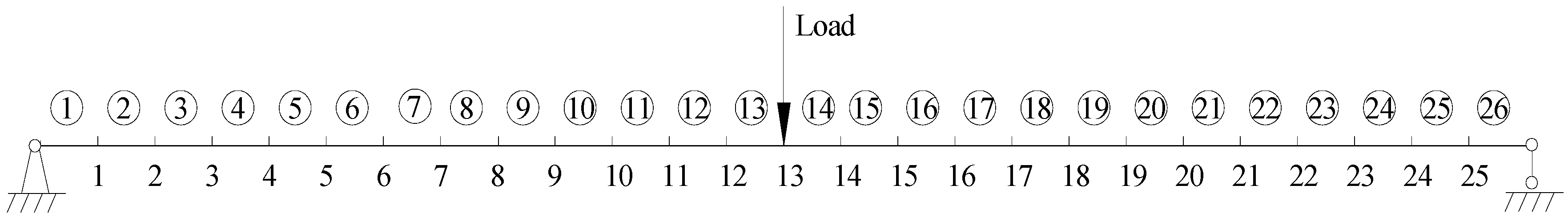
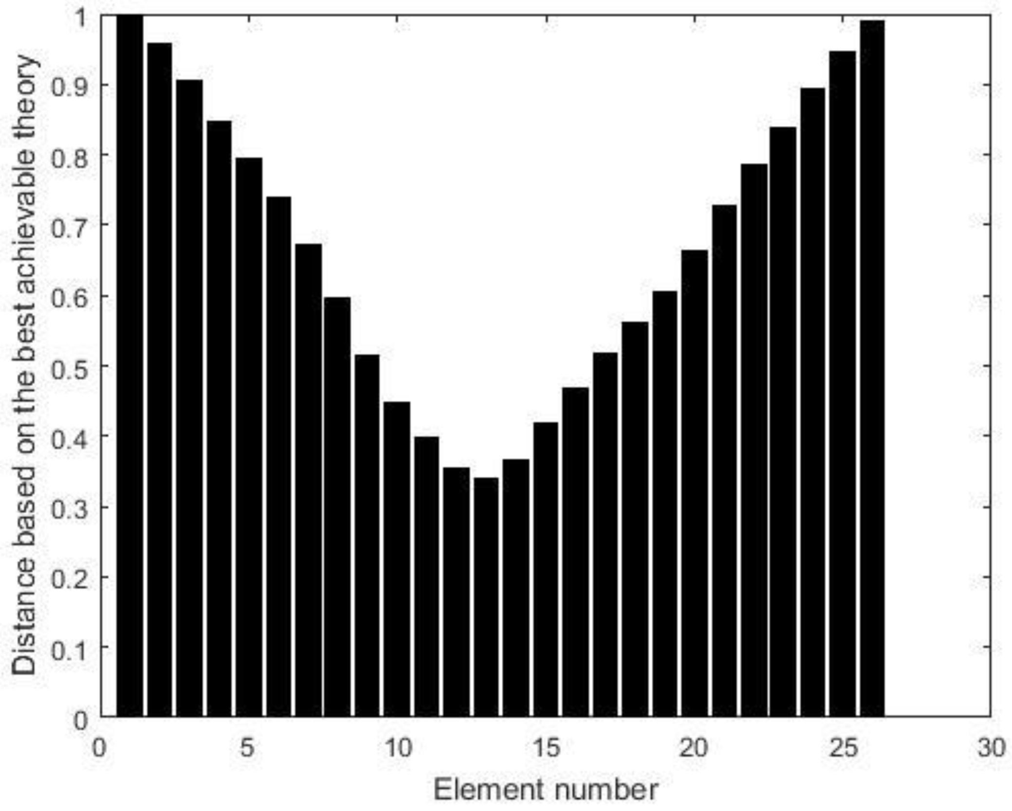
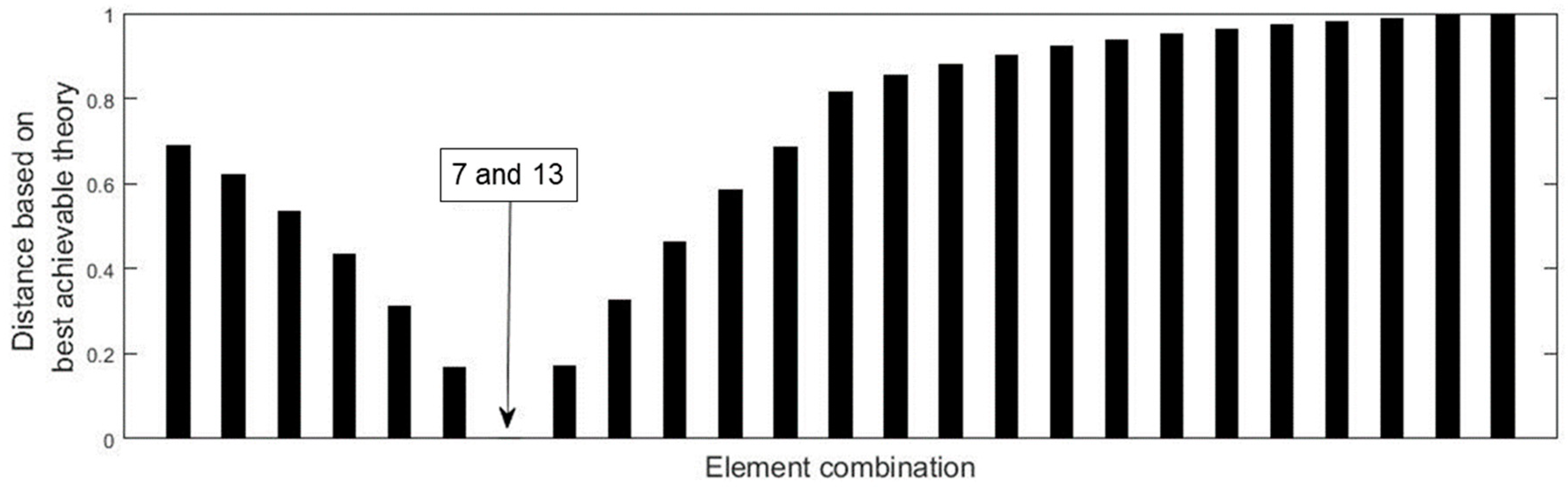
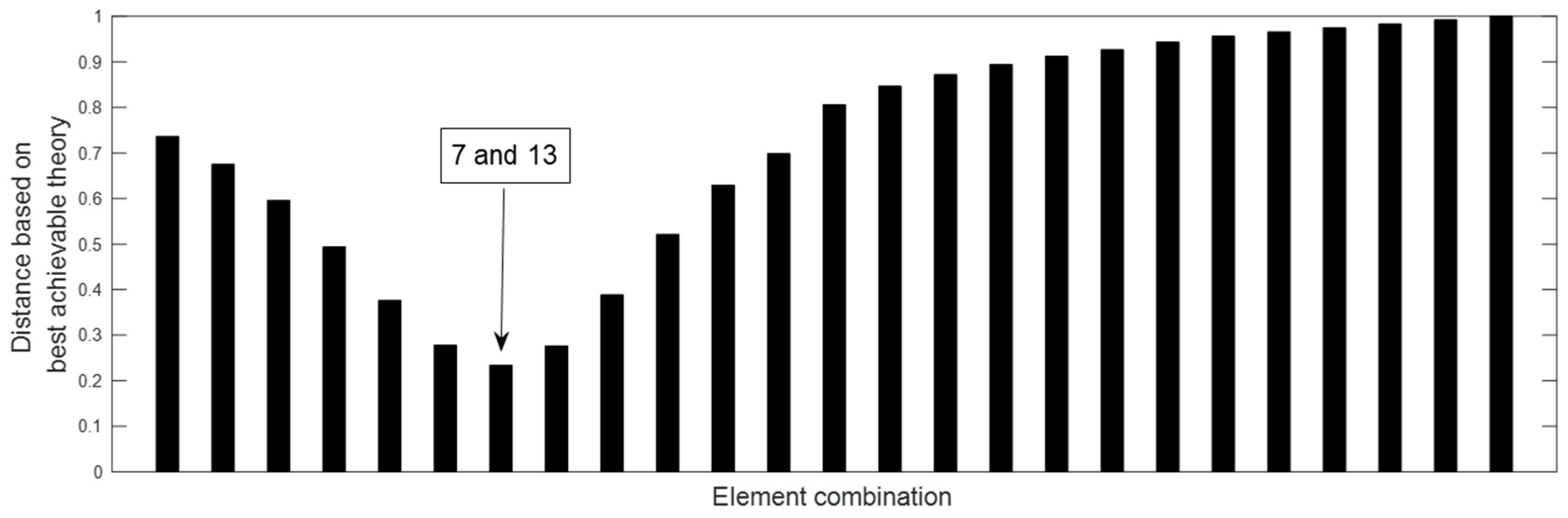
3. Verification by the Numerical Example
4. Verification by the Experimental Example
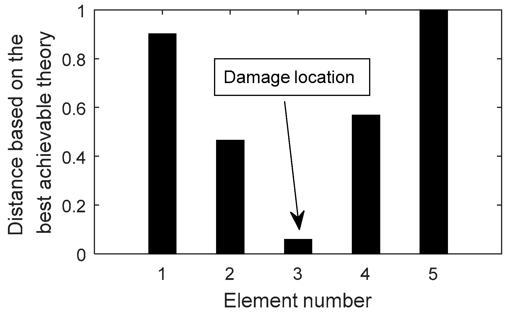
4.1. A Channel Steel Beam
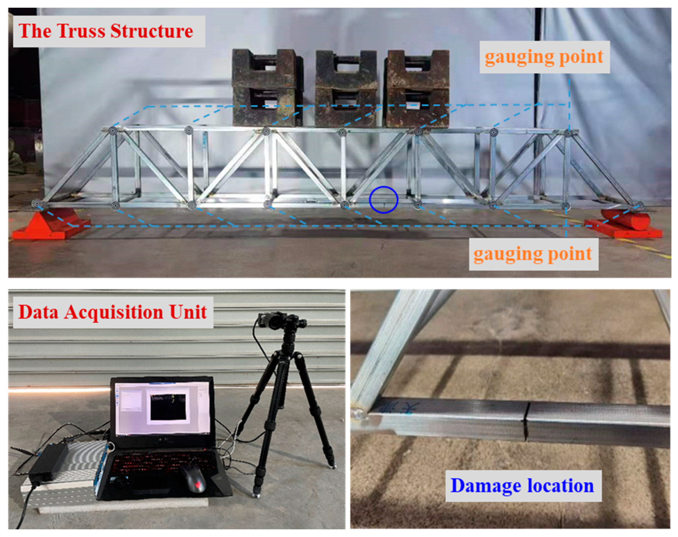
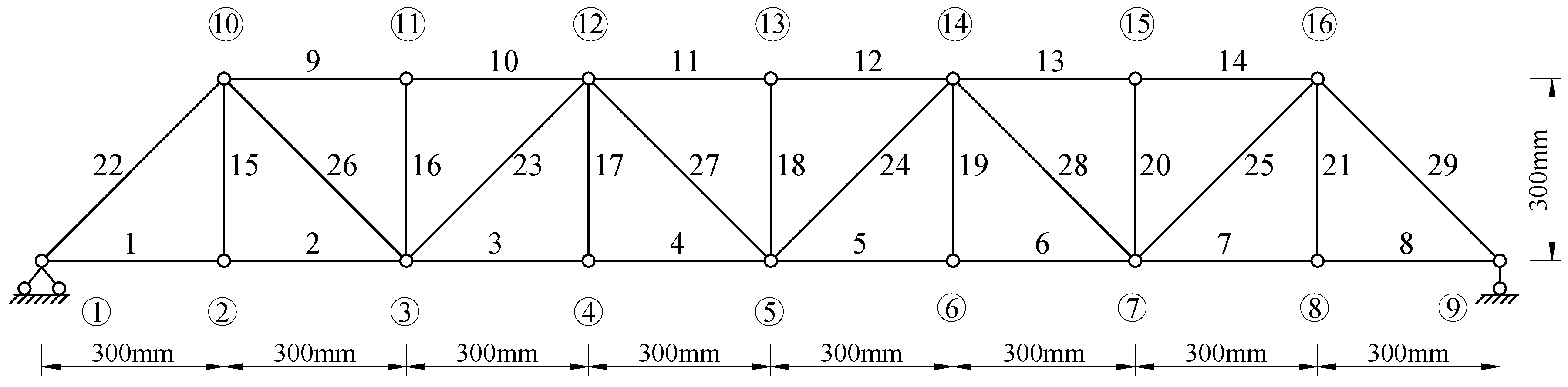
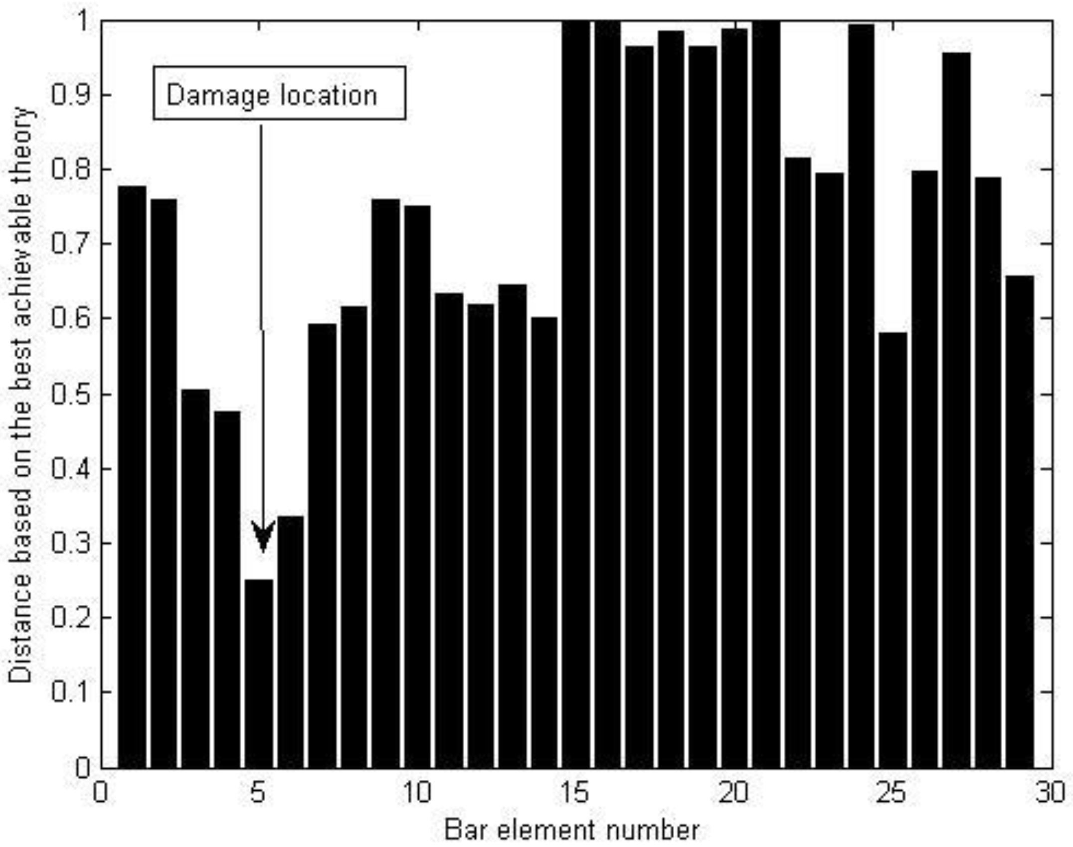
4.2. A Steel Truss Structure
5. Conclusions
Author Contributions
Funding
Institutional Review Board Statement
Informed Consent Statement
Data Availability Statement
Conflicts of Interest
References
- Sun, Y.; Yang, Q.; Peng, X. Damage Identification for Shear-Type Structures Using the Change of Generalized Shear Energy. Coatings 2022, 12, 192. [Google Scholar] [CrossRef]
- Sun, Y.; Yang, Q.; Peng, X. Structural Damage Assessment Using Multiple-Stage Dynamic Flexibility Analysis. Aerospace 2022, 9, 295. [Google Scholar] [CrossRef]
- Sun, L.; Shang, Z.; Xia, Y.; Bhowmick, S.; Nagarajaiah, S. Review of Bridge Structural Health Monitoring Aided by Big Data and Artificial Intelligence: From Condition Assessment to Damage Detection. Eng. Struct. 2020, 146, 04020073. [Google Scholar] [CrossRef]
- Lee, E.T.; Eun, H.C. Damage detection of damaged beam by constrained displacement curvature. J. Mech. Sci. Technol. 2008, 22, 1111–1120. [Google Scholar] [CrossRef]
- Jin, W.M.; Yang, Q.W.; Zhao, W. Damage diagnosis by an improved static-based method. J. Mech. Strength 2012, 34, 190–193. [Google Scholar]
- Song, J.H.; Lee, E.T.; Eun, H.C. Optimal sensor placement through expansion of static strain measurements to static displacements. Int. J. Distrib. Sens. Netw. 2021, 17, 1550147721991712. [Google Scholar] [CrossRef]
- Ma, Q.; Solís, M.; Galvín, P. Wavelet analysis of static deflections for multiple damage identification in beams. Mech. Syst. Signal Process. 2021, 147, 107103. [Google Scholar] [CrossRef]
- Wang, W.; Su, M.; Wang, C. Static Deflection Difference-Based Damage Identification of Hanger in Arch Bridges. KSCE J. Civ. Eng. 2022, 26, 5096–5106. [Google Scholar] [CrossRef]
- Wang, D.; Song, H.; Zhu, H. Numerical and experimental studies on damage detection of a concrete beam based on PZT admittances and correlation coefficient. Constr. Build. Mater. 2013, 49, 564–574. [Google Scholar] [CrossRef]
- Dahak, M.; Touat, N.; Kharoubi, M. Damage detection in beam through change in measured frequency and undamaged curvature mode shape. Inverse Probl. Sci. Eng. 2019, 27, 89–114. [Google Scholar] [CrossRef]
- Zhong, S.; Oyadiji, S.O.; Ding, K. Response-only method for damage detection of beam-like structures using high accuracy frequencies with auxiliary mass spatial probing. J. Sound Vib. 2008, 311, 1075–1099. [Google Scholar] [CrossRef]
- Gillich, G.-R.; Maia, N.; Wahab, M.; Tufisi, C.; Korka, Z.-I.; Gillich, N.; Pop, M. Damage detection on a beam with multiple cracks: A simplified method based on relative frequency shifts. Sensors 2021, 21, 5215. [Google Scholar] [CrossRef] [PubMed]
- Mousavi, M.; Holloway, D.; Olivier, J.C.; Gandomi, A.H. Beam damage detection using synchronisation of peaks in instantaneous frequency and amplitude of vibration data. Measurement 2021, 168, 108297. [Google Scholar] [CrossRef]
- Mostafa, N.; Maio, D.D.; Loendersloot, R.; Tinga, T. Railway bridge damage detection based on extraction of instantaneous frequency by Wavelet Synchrosqueezed Transform. Adv. Bridge Eng. 2022, 3, 12. [Google Scholar] [CrossRef]
- Unger, J.F.; Teughels, A.; De Roeck, G. Damage detection of a prestressed concrete beam using modal strains. J. Struct. Eng. 2005, 131, 1456–1463. [Google Scholar] [CrossRef]
- Tran-Ngoc, H.; Khatir, S.; De Roeck, G.; Bui-Tien, T.; Wahab, M.A. An efficient artificial neural network for damage detection in bridges and beam-like structures by improving training parameters using cuckoo search algorithm. Eng. Struct. 2019, 199, 109637. [Google Scholar] [CrossRef]
- Altunışık, A.C.; Okur, F.Y.; Kahya, V. Modal parameter identification and vibration based damage detection of a multiple cracked cantilever beam. Eng. Fail. Anal. 2017, 79, 154–170. [Google Scholar] [CrossRef]
- Yang, Q.; Peng, X. A highly efficient method for structural model reduction. Int. J. Numer. Methods Eng. 2022, 2022, 1–21. [Google Scholar] [CrossRef]
- Yang, Q.; Peng, X. Sensitivity Analysis Using a Reduced Finite Element Model for Structural Damage Identification. Materials 2021, 14, 5514. [Google Scholar] [CrossRef]
- Pooya, S.M.H.; Massumi, A. A novel and efficient method for damage detection in beam-like structures solely based on damaged structure data and using mode shape curvature estimation. Appl. Math. Model. 2021, 91, 670–694. [Google Scholar] [CrossRef]
- Ahmadi-Nedushan, B.; Fathnejat, H. A modified teaching–learning optimization algorithm for structural damage detection using a novel damage index based on modal flexibility and strain energy under environmental variations. Eng. Comput. 2022, 38, 847–874. [Google Scholar] [CrossRef]
- He, W.-Y.; Ren, W.-X.; Cao, L.; Wang, Q. FEM Free Damage Detection of Beam Structures Using the Deflections Estimated by Modal Flexibility Matrix. Int. J. Struct. Stab. Dyn. 2021, 21, 2150128. [Google Scholar] [CrossRef]
- Bernagozzi, G.; Quqa, S.; Landi, L.; Diotallevi, P.P. Structure-type classification and flexibility-based detection of earthquake-induced damage in full-scale RC buildings. J. Civ. Struct. Health Monit. 2022, 12, 1443–1468. [Google Scholar] [CrossRef]
- Liu, H.; Wu, B.; Li, Z. The generalized flexibility matrix method for structural damage detection with incomplete mode shape data. Inverse Probl. Sci. Eng. 2021, 29, 2019–2039. [Google Scholar] [CrossRef]
- Peng, X.; Yang, Q. Sensor placement and structural damage evaluation by improved generalized flexibility. IEEE Sens. J. 2021, 21, 11654–11664. [Google Scholar] [CrossRef]
- Lim, T.W.; Kashangaki, T.A.L. Structural damage detection of space truss structures using best achievable eigenvectors. AIAA J. 1994, 32, 1049–1057. [Google Scholar] [CrossRef]
- Zhao, Q.; Zhou, Z. Structural damage detection with damage induction vector and best achievable vector. J. Shanghai Univ. 1997, 1, 214–220. (In English) [Google Scholar] [CrossRef]
- Ricci, S. Best achievable modal eigenvectors in structural damage detection. Exp. Mech. 2000, 40, 425–429. [Google Scholar] [CrossRef]
- Prajapat, K.; Ray-Chaudhuri, S. Detection of multiple damages employing best achievable eigenvectors under Bayesian inference. J. Sound Vib. 2018, 422, 237–263. [Google Scholar] [CrossRef]
- Yang, Q.; Sun, B.; Lu, C. An improved spectral decomposition flexibility perturbation method for finite element model updating. Adv. Mech. Eng. 2018, 10, 1687814018814920. [Google Scholar] [CrossRef]
- Yang, Q. Fast and Exact Algorithm for Structural Static Reanalysis Based on Flexibility Disassembly Perturbation. AIAA J. 2019, 57, 3599–3607. [Google Scholar] [CrossRef]
- Le, N.; Thambiratnam, D.; Nguyen, A.; Chan, T. A new method for locating and quantifying damage in beams from static deflection changes. Eng. Struct. 2019, 180, 779–792. [Google Scholar] [CrossRef]


| Parameter | Material | Modulus of Elasticity | Poisson’s Ratio | Mass Density | Section | Width | Depth | Thickness |
|---|---|---|---|---|---|---|---|---|
| Value | Steel | 2.06 × 10⁵ MPa | 0.3 | 7850 kg/m3 | Square tube | 20 mm | 20 mm | 1.2 mm |
Publisher’s Note: MDPI stays neutral with regard to jurisdictional claims in published maps and institutional affiliations. |
© 2022 by the authors. Licensee MDPI, Basel, Switzerland. This article is an open access article distributed under the terms and conditions of the Creative Commons Attribution (CC BY) license (https://creativecommons.org/licenses/by/4.0/).
Share and Cite
Peng, X.; Tian, C.; Yang, Q. Structural Damage Identification Using the Optimal Achievable Displacement Variation. Materials 2022, 15, 8440. https://doi.org/10.3390/ma15238440
Peng X, Tian C, Yang Q. Structural Damage Identification Using the Optimal Achievable Displacement Variation. Materials. 2022; 15(23):8440. https://doi.org/10.3390/ma15238440
Chicago/Turabian StylePeng, Xi, Cunkang Tian, and Qiuwei Yang. 2022. "Structural Damage Identification Using the Optimal Achievable Displacement Variation" Materials 15, no. 23: 8440. https://doi.org/10.3390/ma15238440
APA StylePeng, X., Tian, C., & Yang, Q. (2022). Structural Damage Identification Using the Optimal Achievable Displacement Variation. Materials, 15(23), 8440. https://doi.org/10.3390/ma15238440