Abstract
Traditional optics usually studies the uniform polarization state of light. Compared with uniform vector beams, non-uniform vector beams have more polarization information. Most of the research on generating cylindrical vector beams using metasurfaces focuses on generating transmitted beams using the geometric phase. However, the geometric phase requires the incident light to be circularly polarized, which limits the design freedom. Here, an all-dielectric reflective metasurface is designed to generate different output light according to the different polarization states of the incident light. By combining the two encoding arrangements of the dynamic phase and the geometric phase, the output light is a radial vector beam when the linearly polarized light is incident along the x-direction. Under the incidence of linearly polarized light along the y-direction, the generated output light is an azimuthal vector beam. Under the incidence of left-handed circularly polarized light, the generated output light is a vortex beam with a topological charge of −1. Under the incidence of right-handed circularly polarized light, the generated output light is a vortex beam with a topological charge of +1. The proposed reflective metasurface has potential applications in generating vector beams with high integration.
1. Introduction
Among the basic properties of light such as intensity, wavelength, phase, and polarization, the research on polarization state with vector properties is the latest development [1,2,3,4,5,6,7,8,9,10]. Traditional optics usually studies the uniform polarization state of light, such as linearly polarized light, circularly polarized light, and elliptically polarized light [11,12,13,14,15,16,17,18,19,20]. In recent years, researchers have paid increasing attention to non-uniformly polarized light [21,22,23,24,25,26,27,28,29,30], such as radially/azimuthally polarized cylindrical vector beams [31,32,33,34,35,36,37,38,39,40,41]. Compared with uniform vector beams, non-uniform vector beams have more polarization information, so their interactions with matter are also more diverse, giving them more potential applications. For example, because the focusing part [42,43] has a larger longitudinal polarization component, tight focusing based on radially-polarized vector light has better characteristics than the traditional focusing system, making it suitable for high-resolution imaging [44], lithography [45], optical trapping [46], and sensing [47].
The traditional methods of generating cylindrical vector beams include birefringence mode selection [48], optical dichroism mode selection [49], photonic crystal mirrors [50], multilayer polarization gratings [51], space-shift phase retarder [52] etc. However, these systems contain various optical devices, so the systems are complex and bulky, and the integration level is low, which hinders the development of vector beams with high integration. With the rise of metasurfaces [53], a new direction has been provided to solve the problem of low integration. Metasurfaces have been widely used in the fields of anomalous refraction [54], lens imaging [55], holographic imaging [56], polarization conversion [57], and the sorting of beams carrying OAM [58,59,60], depending on the content and method of light regulation. On-chip waveguides in integrated photonic devices [61] can also manipulate the polarization state of light through precise deformation control of the waveguide cross-sections, and can be fabricated into on-chip optical vortex detectors [62]. Most of the research on generating cylindrical vector beams using metasurfaces focuses on generating transmission beams by the geometric phase, but the geometric phase requires the incident light to be circularly polarized, which limits the freedom of design.
The terahertz wave is between the visible wave and the microwave. Because the rotational vibration of many biological macromolecules falls in this band, the application of terahertz in biomedicine has great prospects. At the same time, polarized optics have the advantages of carrying a large amount of information without the need for exogenous labels, and are increasingly widely used in biomedicine. The application of cylindrical vector beams in the terahertz band is essential for both biomedicine and terahertz communications.
This paper proposes a method for generating vector beams using a reflective all-dielectric metasurface in the terahertz band through the dynamic phase and the geometric phase. As shown in Figure 1, the different types of beams are generated when the beams with different polarization states are incident on the designed metasurface. Under the incidence of linearly polarized light along the x-direction, the generated light is a radial vector beam. Under the incidence of linearly polarized light along the y-direction, the generated light is an angular vector beam. When a left-handed circularly polarized light is incident, the generated light is a vortex beam with a topological charge of −1. Under the incidence of right-handed circularly polarized light, the generated light is a vortex beam with a topological charge of +1. The proposed method can provide a new approach to designing reflective terahertz micro-nano devices.
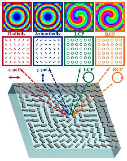
Figure 1.
Schematic diagram of the function of reflective metasurfaces.
2. Theory of Multi-Function Metasurface
Considering that the optical characteristics of the metasurface are the same as that of the phase retarder, when the long axis and the short axis of the designed structure coincide with the x-axis and y-axis of the coordinate system, respectively, the transmission matrix can be conveniently simplified and expressed as: , where and are the amplitude and phase of polarized incidence along the x-axis, and and are the amplitude and phase of polarized incidence along the y-axis. When the structural unit rotates by θ, the long and short axes of the structure do not coincide with the x and y axes, and the transfer matrix is expressed as:
Among them, since the long and short axes do not coincide with the x and y axes, and are the amplitude and phase of the polarized incidence along the x-axis when the structure is not rotated, and and are the amplitude and phase of the polarized incidence along the y-axis when the structure is not rotated. To improve the polarization conversion efficiency, we can consider the special cases of and . According to Euler’s formula, it can be known that , and at this time, Equation (1) is simplified to:
From Equation (2), it can be concluded that the transmission matrix can be changed by changing the long axis or short axis of the structure and the angle of the rotating unit structure, thereby affecting the output light.
A linearly polarized plane wave can be decomposed into two circularly polarized lights. Considering the two circularly polarized lights as: and , respectively, at this time, the reflected output light of the structure is:
Among them, represents the left-handed component of the reflected output light under the incidence of left-hand circularly polarized light, and represents the right-handed component of the reflected output light under the incidence of the right-handed circularly polarized light. ±2θ is the geometric phase.
For the radial/azimuthal vector light field with the same concentric polarization rotation direction, the interface phase distribution should satisfy [63]:
In Equation (5), NA is the numerical aperture, NA = λ/P, λ is the operating wavelength, P is the total period of the 2π phase along the radial direction, and is the topological charge number. Therefore, the phase that needs to be designed can be expressed as: , . According to Equations (3) and (4), we can obtain:
It can be seen from Equation (6) that when the incident light is left-handed circularly polarized light, the left-handed component of the reflected light is a vortex beam with a topological charge of −1. Similarly, it can be observed from Equation (7) that when the incident light is right-handed circularly polarized light, the right-handed component of the reflected light is a vortex beam with a topological charge of +1. When a linearly polarized light is incident, the output light can be expressed as:
In Formula (8), when the linearly polarized light is incident along the x-direction (β = 0), the output light is radial vector light, and when the linearly polarized light is incident in the y-direction (β = π/2), the outgoing light is azimuthal vector light.
3. Design of Multi-Function Metasurfaces
Figure 2 is a schematic diagram of a reflective metasurface, which is high-resistance silicon with a relative dielectric constant of 11.7 and a thickness of h = 180 μm on fused silica. The period P of the high resistance silicon pillar is 300 μm. By changing the lengths and in two orthogonal directions of the silicon pillar, its phase can be controlled to cover the entire 2π range [64]. At the same time, an additional PB phase is generated by rotating the silicon pillar. The metasurface acts as a half-wave plate, and a phase difference of π is required between the principal axes of the designed metasurface units. To improve the polarization conversion efficiency, we can consider the special cases of and in which the silicon pillar acts as a half-wave plate. In Equation (2), is the phase of the silicon pillar along the direction, θ is the rotation angle of the structure, and 2θ is the geometric phase. Among them, the phase of the output light is changed by changing the length and width of the silicon pillar to meet the half-wave plate function, and the angle of the silicon pillar is rotated to meet different incident light polarization states, through which each metasurface unit is individually designed to achieve a specified polarization conversion.
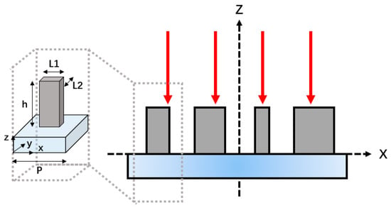
Figure 2.
Schematic diagram of the reflective metasurface structure.
Figure 3a,b show the phase and amplitude results of changing and of the silicon pillar at 0.7 THz. Accordingly, the corresponding operating wavelength is 428.6 μm. The full 2π phase regulation at 0.7 THz is achieved by changing the lengths of and . The location of the selected four coding structures is marked in the figure. As shown in Table 1, the structure sizes of the four units are selected as = 120, 86, 270, 260 μm and = 270, 260, 120, 86 μm. Figure 3c shows the amplitude values under the incident polarization along the x-direction and the amplitude values under the incident polarization along the y-direction. The amplitude difference is , corresponding to the four coding structures. Figure 3d shows the phase value under the incident polarization along the x-direction and the phase value under the incident polarization along the y-direction. The phase difference value is , corresponding to the four coding structures. The phase of four coding structures are linearly increased in 90° steps. At the same time, to ensure that all selected coding structures play the role of half-wave plates at the selected frequency of 0.7 THz, the phase differences are close to π. Based on these four coded silicon pillars, a metasurface was designed for generating vector beams.
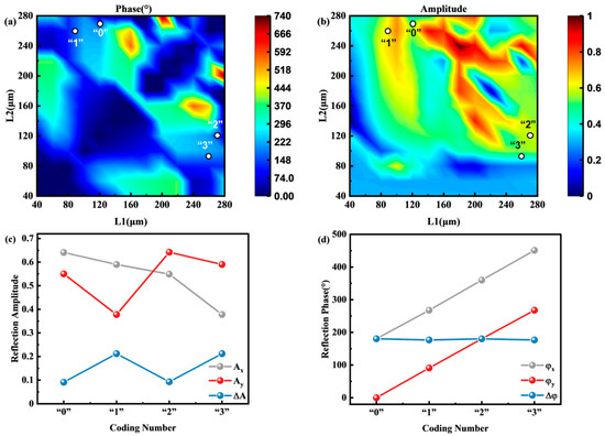
Figure 3.
(a,b) The phase and amplitude spectra of silicon pillars changing and at 0.7 THz; the numbers in the figure indicate the size selection of the four coding structures. (c) The amplitude values along with the x-direction corresponding to the four coding structures; the amplitude value along the y-direction, and the amplitude difference . (d) The phase value along with the x-direction corresponding to the four coding structures; the phase value along the y-direction and the phase difference value .

Table 1.
Parameter settings. (Unit: μm).
Under the incident polarization along the x-direction, the emergent light is a radial vector beam, and under the incident polarization along the y-direction, the emergent light is an angular vector beam. To realize the above design, the four coding structures are firstly arranged according to radial diffusion. Different from this phase modulation, the metasurface is also evenly divided into eight regions, and the arranged coding structures in each region are rotated by the same angle θ. The θ angle is determined by the required phase α = 2θ, as shown in Figure 4. The phase changes of the two encoding methods are simply illustrated in Figure 4.
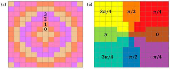
Figure 4.
(a,b) Colors indicating the phase change of the two encoding methods.
Among them, the four colors in Figure 4a represent four coding structures, respectively, that are determined by changing and to form the dynamic phase. The eight region phases α of Figure 4b are arranged in rotation from 0 to 2π, thereby forming the second PB phase. The designed metasurfaces are arranged according to the above arrangement.
Silicon dioxide can be deposited on high-resistance silicon wafers by plasma chemical vapor deposition. The silicon wafer was directly bonded to the fused silica wafer by spin-on adhesive followed by UV exposure. The photoresist lithography and deep reactive ion etching process are etched using traditional mask lithography technology. High-resistance silicon is widely used in terahertz optics due to its low loss and low dispersion in the terahertz spectrum. The metasurface is composed of 13 × 13-unit structures. Figure 5a is the normalized intensity distribution at 0.7 THz under the incidence of x-polarized light. It can be seen that the light intensity distribution is a doughnut shape with a hollow center. The intensity outside this shape is relatively low, and the arrows in the figure indicate the polarization distribution, which is radially directed toward the concentricity. The polarization states represented by the arrows are the calculated results of the vector electric field obtained by the simulation. Figure 5b shows the yz plane intensity distribution of the generated vector beam under the incident x-polarized light without diffraction characteristics. Figure 6a shows the normalized intensity distribution at 0.7 THz under the incidence of y-polarized light. The normalization factor is , and represents the intensity of the plane electric field. It can also be clearly seen that the light intensity distribution is in the shape of a donut with a hollow center. The polarization distribution of the arrow in the figure is an angular distribution with the same rotation direction. Figure 6b is the intensity distribution of the yz plane under the incident y-polarized light. It can be seen that the emergent beam has a long non-diffraction distance of about 10λ. The results are very consistent with the idea of the theoretical design. Under the incidence of y-polarized light, the halo of azimuthal vector beams generated by the metasurface is more uniform. However, under the incidence of x-polarized light, the radial vector beam halo generated by the metasurface has poor uniformity. Fortunately, by increasing the number of coding metaunits to refine the phase change, this inhomogeneity can be reduced. It can also be optimized by increasing the resolution in the pattern design. When designing the units, the amplitude and phase of each cell should be relatively uniform.
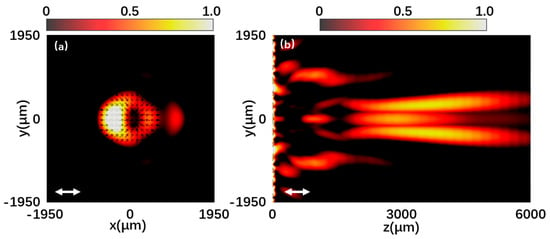
Figure 5.
(a,b) Normalized intensity distribution at 0.7 THz under the x-polarized light incidence.

Figure 6.
(a,b) Normalized intensity distribution at 0.7 THz under the y-polarized light incidence.
Figure 7 and Figure 8 are the left-handed and right-handed component intensities and phase distributions when the metasurface is illuminated by left-handed circularly polarized light and right-handed circularly polarized light, respectively. Figure 7a is the normalized intensity distribution of the left-handed component of the reflected beam at 0.7 THz under left-handed polarized light incidence. A hollow doughnut-shaped vortex beam in the center is shown. Figure 7b shows the phase distribution corresponding to the left-handed component, and the helical phase distribution indicates that the output light is a vortex beam with a topological charge of −1. In contrast, the intensity distribution and phase distribution of the right-handed component in Figure 7c,d are irregular. Likewise, in Figure 8, the left-handed and right-handed components exhibit the same theoretical effect when the incident light polarization is opposite. The simulation results provide a good demonstration of the vortex beam properties of the generated beam.
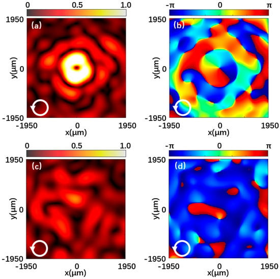
Figure 7.
Reflected beam at 0.7 THz under the left-handed polarized light incidence. (a,b) Normalized intensity distribution and phase distribution of the left-handed component. (c,d) Normalized intensity distribution and phase distribution of the right-handed component.
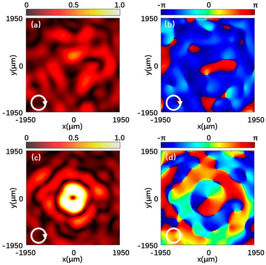
Figure 8.
Reflected beam at 0.7 THz under the right-handed polarized light incidence. (a,b) Normalized intensity distribution and phase distribution of the left-handed component. (c,d) Normalized intensity distribution and phase distribution of the right-handed component.
The OAM patterns were quantitatively analyzed by employing Fourier transform analysis. The formula is as follows [65]:
As shown in Figure 9, the OAM topological charge number l = −7 to 7 is selected, and the energy weight of the OAM topological charge number is defined as:
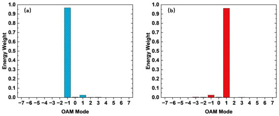
Figure 9.
OAM spectrum. (a) Topological charge distribution of the left-handed component under the incidence of left-handed polarized light. (b) Topological charge distribution of the right-handed component under the incidence of right-handed polarized light.
It can be seen that for the left-handed component in Figure 9a, the topological charge number accounts for the main part of the component, and the remaining topological charge number components are relatively small. In the right-handed component in Figure 9b, the topological charge number accounts for the main component.
4. Conclusions
We propose a method for generating vector beams in the terahertz band using an all-dielectric reflection-type metasurface. By using the superposition of the dynamic phase and the PB phase of the encoding unit structure at the same time, the generation of the vector beams under the incidence of linearly polarized light can be realized. The metasurface is composed of four kinds of coded cell structures, all of which have a half-wave plate function and fully cover the 2π phase. The proposed reflective metasurface has potential applications in generating vector beams with high integration. The method can be extended to other frequency ranges.
Author Contributions
Conceptualization, X.J. and C.L.; writing—original draft preparation, Q.W.; writing—review and editing, B.F.; visualization, C.L.; supervision, X.J. All authors have read and agreed to the published version of the manuscript.
Funding
This research was funded by the Natural Science Foundation of Zhejiang Province, grant number LY20F050007, LZ21A040003, and LY22F050001; the National Natural Science Foundation of China (NSFC), grant number 62175224; the Zhejiang University Students Science and Technology Innovation Program (New Talent Program) Project, grant number 2022R409055; and the Fundamental Research Funds for the Provincial Universities of Zhejiang, grant number 2021YW70.
Institutional Review Board Statement
Not applicable.
Informed Consent Statement
Not applicable.
Data Availability Statement
The data presented in this study are openly available.
Conflicts of Interest
The authors declare no conflict of interest.
References
- He, X.Y. Tunable terahertz graphene metamaterials. Carbon 2015, 82, 229–237. [Google Scholar] [CrossRef]
- He, X.Y.; Zhong, X.; Lin, F.T.; Shi, W.Z. Investigation of graphene assisted tunable terahertz metamaterials absorber. Opt. Mater. Express 2016, 6, 331–342. [Google Scholar] [CrossRef]
- He, X.Y.; Liu, F.; Lin, F.T.; Shi, W.Z. Tunable 3D Dirac-semimetals supported mid-IR hybrid plasmonic waveguides. Opt. Lett. 2021, 46, 472–475. [Google Scholar] [CrossRef] [PubMed]
- He, X.Y.; Liu, F.; Lin, F.T.; Shi, W.Z. Tunable terahertz Dirac semimetal metamaterials. J. Phys. D Appl. Phys. 2021, 54, 9. [Google Scholar] [CrossRef]
- Peng, J.; He, X.Y.; Shi, C.Y.Y.; Leng, J.; Lin, F.T.; Liu, F.; Zhang, H.; Shi, W.Z. Investigation of graphene supported terahertz elliptical metamaterials. Phys. E 2020, 124, 8. [Google Scholar] [CrossRef]
- Jing, X.F.; Jin, S.Z.; Tian, Y.; Liang, P.; Dong, Q.M.; Wang, L. Analysis of the sinusoidal nanopatterning grating structure. Opt. Laser Technol. 2013, 48, 160–166. [Google Scholar] [CrossRef]
- Jing, X.F.; Xu, Y.N.; Gan, H.Y.; He, Y.W.; Hong, Z. High Refractive Index Metamaterials by Using Higher Order Modes Resonances of Hollow Cylindrical Nanostructure in Visible Region. IEEE Access 2019, 7, 144945–144956. [Google Scholar] [CrossRef]
- Jiang, L.; Fang, B.; Yan, Z.G.; Fan, J.; Qi, C.K.; Liu, J.J.; He, Y.W.; Li, C.X.; Jing, X.F.; Gan, H.Y.; et al. Terahertz high and near-zero refractive index metamaterials by double layer metal ring microstructure. Opt. Laser Technol. 2020, 123, 12. [Google Scholar] [CrossRef]
- Lv, H.R.; Lu, X.Q.; Han, Y.S.; Mou, Z.; Teng, S.Y. Multifocal metalens with a controllable intensity ratio. Opt. Lett. 2019, 44, 2518–2521. [Google Scholar] [CrossRef]
- Wang, H.; Liu, L.X.; Zhou, C.D.; Xu, J.L.; Zhang, M.N.; Teng, S.Y.; Cai, Y.J. Vortex beam generation with variable topological charge based on a spiral slit. Nanophotonics 2019, 8, 317–324. [Google Scholar] [CrossRef]
- Li, J.X.; Yuan, Y.Y.; Wu, Q.; Burokur, S.N.; Zhang, K. Dual-band independent phase control based on high efficiency metasurface Invited. Chin. Opt. Lett. 2021, 19, 8. [Google Scholar] [CrossRef]
- Teng, S.Y.; Zhang, Q.; Wang, H.; Liu, L.X.; Lv, H.R. Conversion between polarization states based on a metasurface. Photonics Res. 2019, 7, 246–250. [Google Scholar] [CrossRef]
- Akram, M.R.; Ding, G.W.; Chen, K.; Feng, Y.J.; Zhu, W.R. Ultrathin Single Layer Metasurfaces with Ultra-Wideband Operation for Both Transmission and Reflection. Adv. Mater. 2020, 32, 8. [Google Scholar] [CrossRef] [PubMed]
- Zhang, J.; Wei, X.Z.; Rukhlenko, I.D.; Chen, H.T.; Zhu, W.R. Electrically Tunable Metasurface with Independent Frequency and Amplitude Modulations. ACS Photonics 2020, 7, 265–271. [Google Scholar] [CrossRef]
- Wang, H.Y.; Zhang, Z.Y.; Zhao, K.; Liu, W.; Wang, P.; Lu, Y.H. Independent phase manipulation of co- and cross- polarizations with all-dielectric metasurface. Chin. Opt. Lett. 2021, 19, 6. [Google Scholar] [CrossRef]
- Fang, B.; Cai, Z.Y.; Peng, Y.D.; Li, C.X.; Hong, Z.; Jing, X.F. Realization of ultrahigh refractive index in terahertz region by multiple layers coupled metal ring metamaterials. J. Electromagn. Waves Appl. 2019, 33, 1375–1390. [Google Scholar] [CrossRef]
- Fang, B.; Li, B.Y.; Peng, Y.D.; Li, C.X.; Hong, Z.; Jing, X.F. Polarization-independent multiband metamaterials absorber by fundamental cavity mode of multilayer microstructure. Microw. Opt. Technol. Lett. 2019, 61, 2385–2391. [Google Scholar] [CrossRef]
- Wang, W.M.; Jing, X.F.; Zhao, J.Y.; Li, Y.Y.; Tian, Y. Improvement of accuracy of simple methods for design and analysis of a blazed phase grating microstructure. Opt. Appl. 2017, 47, 183–198. [Google Scholar]
- Jiang, L.; Fang, B.; Yan, Z.G.; Li, C.X.; Fu, J.P.; Gan, H.Y.; Hong, Z.; Jing, X.F. Improvement of unidirectional scattering characteristics based on multiple nanospheres array. Microw. Opt. Technol. Lett. 2020, 62, 2405–2414. [Google Scholar] [CrossRef]
- Zhao, Y.; Huang, Q.P.; Cai, H.L.; Lin, X.X.; He, H.C.; Cheng, H.; Ma, T.; Lu, Y.L. Ultrafast control of slow light in THz electromagnetically induced transparency metasurfaces. Chin. Opt. Lett. 2021, 19, 6. [Google Scholar] [CrossRef]
- Khaliq, H.S.; Kim, I.; Zahid, A.; Kim, J.; Lee, T.; Badloe, T.; Kim, Y.; Zubair, M.; Riaz, K.; Mehmood, M.Q.; et al. Giant chiro-optical responses in multipolar-resonances-based single-layer dielectric metasurfaces. Photonics Res. 2021, 9, 1667–1674. [Google Scholar] [CrossRef]
- Parry, M.; Mazzanti, A.; Poddubny, A.; Della Valle, G.; Neshev, D.N.; Sukhorukov, A.A. Enhanced generation of nondegenerate photon pairs in nonlinear metasurfaces. Adv. Photonics 2021, 3, 21. [Google Scholar] [CrossRef]
- Du, A.; Ma, Y.; Liu, M.F.; Zhang, Z.H.; Cao, G.W.; Li, H.W.; Wang, L.; Si, P.J.; Shen, J.; Zhou, B. Morphology analysis of tracks in the aerogels impacted by hypervelocity irregular particles. High Power Laser Sci. Eng. 2021, 9, 9. [Google Scholar] [CrossRef]
- Ebert, T.; Heber, R.; Abel, T.; Bieker, J.; Schaumann, G.; Roth, M. Targets with cone-shaped microstructures from various materials for enhanced high-intensity laser-matter interaction. High Power Laser Sci. Eng. 2021, 9, 6. [Google Scholar] [CrossRef]
- Xie, X.H.; Deng, Y.P.; Johnson, S.L. Compact and robust supercontinuum generation and post-compression using multiple thin plates. High Power Laser Sci. Eng. 2021, 9, 8. [Google Scholar] [CrossRef]
- Zhang, J.; Zhang, H.; Yang, W.X.; Chen, K.; Wei, X.Z.; Feng, Y.J.; Jin, R.H.; Zhu, W.R. Dynamic Scattering Steering with Graphene-Based Coding Metamirror. Adv. Opt. Mater. 2020, 8, 8. [Google Scholar] [CrossRef]
- Bai, X.D.; Kong, F.W.; Sun, Y.T.; Wang, G.F.; Qian, J.Y.; Li, X.B.; Cao, A.J.; He, C.; Liang, X.L.; Jin, R.H.; et al. High-Efficiency Transmissive Programmable Metasurface for Multimode OAM Generation. Adv. Opt. Mater. 2020, 8, 9. [Google Scholar] [CrossRef]
- Jing, X.F.; Gui, X.C.; Zhou, P.W.; Hong, Z. Physical Explanation of Fabry-Perot Cavity for Broadband Bilayer Metamaterials Polarization Converter. J. Lightwave Technol. 2018, 36, 2322–2327. [Google Scholar] [CrossRef]
- Xia, R.; Jing, X.F.; Gui, X.C.; Tian, Y.; Hong, Z. Broadband terahertz half-wave plate based on anisotropic polarization conversion metamaterials. Opt. Mater. Express 2017, 7, 977–988. [Google Scholar] [CrossRef]
- Akram, M.R.; Mehmood, M.Q.; Bai, X.D.; Jin, R.H.; Premaratne, M.; Zhu, W.R. High Efficiency Ultrathin Transmissive Metasurfaces. Adv. Opt. Mater. 2019, 7, 7. [Google Scholar] [CrossRef]
- Akram, M.R.; Bai, X.D.; Jin, R.H.; Vandenbosch, G.A.E.; Premaratne, M.; Zhu, W.R. Photon Spin Hall Effect-Based Ultra-Thin Transmissive Metasurface for Efficient Generation of OAM Waves. IEEE Trans. Antennas Propag. 2019, 67, 4650–4658. [Google Scholar] [CrossRef]
- Zhao, J.Y.; Jing, X.F.; Wang, W.M.; Tian, Y.; Zhu, D.S.; Shi, G.H. Steady method to retrieve effective electromagnetic parameters of bianisotropic metamaterials at one incident direction in the terahertz region. Opt. Laser Technol. 2017, 95, 56–62. [Google Scholar] [CrossRef]
- Tian, Y.; Jing, X.F.; Gan, H.Y.; Li, C.X.; Hong, Z. Free control of far-field scattering angle of transmission terahertz wave using multilayer split-ring resonators’ metasurfaces. Front. Phys. 2020, 15, 8. [Google Scholar] [CrossRef]
- Zhou, C.D.; Mou, Z.; Bao, R.; Li, Z.; Teng, S.Y. Compound plasmonic vortex generation based on spiral nanoslits. Front. Phys. 2021, 16, 8. [Google Scholar] [CrossRef]
- Dai, G.L. Designing nonlinear thermal devices and metamaterials under the Fourier law: A route to nonlinear thermotics. Front. Phys. 2021, 16, 36. [Google Scholar] [CrossRef]
- Lan, L.L.; Gao, Y.M.; Fan, X.C.; Li, M.Z.; Hao, Q.; Qiu, T. The origin of ultrasensitive SERS sensing beyond plasmonics. Front. Phys. 2021, 16, 26. [Google Scholar] [CrossRef]
- Li, J.P.; Jin, R.H.; Geng, J.P.; Liang, X.L.; Wang, K.; Premaratne, M.; Zhu, W.R. Design of a Broadband Metasurface Luneburg Lens for Full-Angle Operation. IEEE Trans. Antennas Propag. 2019, 67, 2442–2451. [Google Scholar] [CrossRef]
- Lu, X.Q.; Zeng, X.Y.; Lv, H.R.; Han, Y.S.; Mou, Z.; Liu, C.X.; Wang, S.Y.; Teng, S.Y. Polarization controllable plasmonic focusing based on nanometer holes. Nanotechnology 2020, 31, 6. [Google Scholar] [CrossRef]
- Lv, H.R.; Lu, X.Q.; Han, Y.S.; Mou, Z.; Zhou, C.D.; Wang, S.Y.; Teng, S.Y. Metasurface cylindrical vector light generators based on nanometer holes. New J. Phys. 2019, 21, 8. [Google Scholar] [CrossRef]
- Fang, B.; Feng, D.T.; Chen, P.; Shi, L.J.; Cai, J.H.; Li, J.M.; Li, C.X.; Hong, Z.; Jing, X.F. Broadband cross-circular polarization carpet cloaking based on a phase change material metasurface in the mid-infrared region. Front. Phys. 2022, 17, 9. [Google Scholar] [CrossRef]
- Zhan, Q.W. Cylindrical vector beams: From mathematical concepts to applications. Adv. Opt. Photonics 2009, 1, 1–57. [Google Scholar] [CrossRef]
- Quabis, S.; Dorn, R.; Eberler, M.; Glöckl, O.; Leuchs, G. Focusing light to a tighter spot. Opt. Commun. 2000, 179, 1–7. [Google Scholar] [CrossRef]
- Dorn, R.; Quabis, S.; Leuchs, G. Sharper focus for a radially polarized light beam. Phys. Rev. Lett. 2003, 91, 233901. [Google Scholar] [CrossRef] [PubMed]
- Tamburini, F.; Anzolin, G.; Umbriaco, G.; Bianchini, A.; Barbieri, C. Overcoming the rayleigh criterion limit with optical vortices. Phys. Rev. Lett. 2006, 97, 163903. [Google Scholar] [CrossRef]
- Dholakia, K.; Reece, P.; Gu, M. Optical micromanipulation. Chem. Soc. Rev. 2008, 37, 42–55. [Google Scholar] [CrossRef]
- Donato, M.G.; Vasi, S.; Sayed, R.; Jones, P.H.; Bonaccorso, F.; Ferrari, A.C.; Gucciardi, P.G.; Marago, O.M. Optical trapping of nanotubes with cylindrical vector beams. Opt. Lett. 2012, 37, 3381–3383. [Google Scholar] [CrossRef]
- Syubaev, S.A.; Zhizhchenko, A.Y.; Pavlov, D.V.; Gurbatov, S.O.; Pustovalov, E.V.; Porfirev, A.P.; Khonina, S.N.; Kulinich, S.A.; Rayappan, J.B.B.; Kudryashov, S.I.; et al. Plasmonic Nanolenses Produced by Cylindrical Vector Beam Printing for Sensing Applications. Sci. Rep. 2019, 9, 8. [Google Scholar] [CrossRef] [PubMed]
- Yonezawa, K.; Kozawa, Y.; Sato, S. Generation of a radially polarized laser beam by use of the birefringence of a c-cut Nd:YVO4 crystal. Opt. Lett. 2006, 31, 2151–2153. [Google Scholar] [CrossRef]
- Kozawa, Y.; Sato, S. Generation of a radially polarized laser beam by use of a conical Brewster prism. Opt. Lett. 2005, 30, 3063–3065. [Google Scholar] [CrossRef]
- Hamazaki, J.; Kawamoto, A.; Morita, R.; Omatsu, T. Direct production of high-power radially-polarized output from a side-pumped Nd: YVO4 bounce amplifier using a photonic crystal mirror. Opt. Express 2008, 16, 10762–10768. [Google Scholar] [CrossRef]
- Ahmed, M.A.; Voss, A.; Vogel, M.M.; Graf, T. Multilayer polarizing grating mirror used for the generation of radial polarization in Yb:YAG thin-disk lasers. Opt. Lett. 2007, 32, 3272–3274. [Google Scholar] [CrossRef] [PubMed]
- Fridman, M.; Machavariani, G.; Davidson, N.; Friesem, A.A. Fiber lasers generating radially and azimuthally polarized light. Appl. Phys. Lett. 2008, 93, 2. [Google Scholar] [CrossRef]
- Yu, N.F.; Genevet, P.; Kats, M.A.; Aieta, F.; Tetienne, J.P.; Capasso, F.; Gaburro, Z. Light Propagation with Phase Discontinuities: Generalized Laws of Reflection and Refraction. Science 2011, 334, 333–337. [Google Scholar] [CrossRef] [PubMed]
- Pfeiffer, C.; Emani, N.K.; Shaltout, A.M.; Boltasseva, A.; Shalaev, V.M.; Grbic, A. Efficient Light Bending with Isotropic Metamaterial Huygens’ Surfaces. Nano Lett. 2014, 14, 2491–2497. [Google Scholar] [CrossRef]
- Urbach, H.P.; Pereira, S.F. Field in focus with a maximum longitudinal electric component. Phys. Rev. Lett. 2008, 100, 4. [Google Scholar] [CrossRef]
- Walther, B.; Helgert, C.; Rockstuhl, C.; Setzpfandt, F.; Eilenberger, F.; Kley, E.B.; Lederer, F.; Tunnermann, A.; Pertsch, T. Spatial and Spectral Light Shaping with Metamaterials. Adv. Mater. 2012, 24, 6300–6304. [Google Scholar] [CrossRef]
- Shaltout, A.; Liu, J.J.; Shalaev, V.M.; Kildishev, A.V. Optically Active Metasurface with Non-Chiral Plasmonic Nanoantennas. Nano Lett. 2014, 14, 4426–4431. [Google Scholar] [CrossRef]
- Wang, B.; Wen, Y.; Zhu, J.; Chen, Y.; Yu, S. Sorting full angular momentum states with Pancharatnam-Berry metasurfaces based on spiral transformation. Opt. Express 2020, 28, 16342–16351. [Google Scholar] [CrossRef]
- Ruffato, G.; Capaldo, P.; Massari, M.; Mafakheri, E.; Romanato, F. Total angular momentum sorting in the telecom infrared with silicon Pancharatnam-Berry transformation optics. Opt. Express 2019, 27, 15750–15764. [Google Scholar] [CrossRef]
- Guo, Y.; Zhang, S.; Pu, M.; He, Q.; Jin, J.; Xu, M.; Zhang, Y.; Gao, P.; Luo, X. Spin-decoupled metasurface for simultaneous detection of spin and orbital angular momenta via momentum transformation. Light Sci. Appl. 2021, 10, 63. [Google Scholar] [CrossRef]
- Sun, B.; Morozko, F.; Salter, P.S.; Moser, S.; Pong, Z.; Patel, R.B.; Walmsley, I.A.; Wang, M.; Hazan, A.; Barré, N.; et al. On-chip beam rotators, adiabatic mode converters, and waveplates through low-loss waveguides with variable cross-sections. Light Sci. Appl. 2022, 11, 214. [Google Scholar] [CrossRef] [PubMed]
- Karabchevsky, A. On-chip optical vortex-based nanophotonic detectors. Light Sci. Appl. 2020, 9, 115. [Google Scholar] [CrossRef] [PubMed]
- Chen, W.T.; Khorasaninejad, M.; Zhu, A.Y.; Oh, J.; Devlin, R.C.; Zaidi, A.; Capasso, F. Generation of wavelength-independent subwavelength Bessel beams using metasurfaces. Light Sci. Appl. 2017, 6, 6. [Google Scholar] [CrossRef] [PubMed]
- Ma, Z.J.; Hanham, S.M.; Albella, P.; Ng, B.H.; Lu, H.T.; Gong, Y.D.; Maier, S.A.; Hong, M.H. Terahertz All-Dielectric Magnetic Mirror Metasurfaces. ACS Photonics 2016, 3, 1010–1018. [Google Scholar] [CrossRef]
- Jack, B.; Padgett, M.J.; Franke-Arnold, S. Angular diffraction. New J. Phys. 2008, 10, 8. [Google Scholar] [CrossRef]
Publisher’s Note: MDPI stays neutral with regard to jurisdictional claims in published maps and institutional affiliations. |
© 2022 by the authors. Licensee MDPI, Basel, Switzerland. This article is an open access article distributed under the terms and conditions of the Creative Commons Attribution (CC BY) license (https://creativecommons.org/licenses/by/4.0/).


