Article

(Cr1−xAlx)N Coating Deposition by Short-Pulse High-Power Dual Magnetron Sputtering

by
Alexander Grenadyorov
,
Vladimir Oskirko
,
Alexander Zakharov
,
Konstantin Oskomov
and
Andrey Solovyev
*
The Institute of High Current Electronics SB RAS, 2/3, Akademichesky Ave., 634055 Tomsk, Russia
*
Author to whom correspondence should be addressed.
Materials 2022, 15(22), 8237; https://doi.org/10.3390/ma15228237
Submission received: 25 October 2022 / Revised: 16 November 2022 / Accepted: 18 November 2022 / Published: 20 November 2022

Abstract

:
The paper deals with the (Cr1−xAlx)N coating containing 17 to 54 % Al which is deposited on AISI 430 stainless steel stationary substrates by short-pulse high-power dual magnetron sputtering of Al and Cr targets. The Al/Cr ratio in the coating depends on the substrate position relative to magnetrons. It is shown that the higher Al content in the (Cr1−xAlx)N coating improves its hardness from 17 to 28 GPa. Regardless of the Al content, the (Cr1−xAlx)N coating manifests a low wear rate, namely (4.1–7.8) × 10−9 and (3.9–5.3) × 10−7 mm3N−1m−1 in using metallic (100Cr6) and ceramic (Al2O3) counter bodies, respectively. In addition, this coating possesses the friction coefficient 0.4–0.7 and adhesive strength quality HF1 and HF2 indicating good interfacial adhesion according to the Daimler-Benz Rockwell-C adhesion test.

1. Introduction

Hard and wear-resistant coatings TiN, TiAlN, CrAlN are widely used to improve the service life of different systems and mechanisms such as cutting and molder tools, friction assemblies, etc. [1,2,3]. In comparison with TiN and TiAlN coatings, the CrAlN coating possesses higher resistance to oxidation at high temperatures (because both chromium and aluminum can form protective oxides, which suppress the oxygen diffusion in the bulk [4,5,6]), and improved wear and corrosion resistance [4].
The CrAlN coating is usually obtained by physical vapor deposition, the widely used arc ion plating (AIP) and cathodic arc evaporation (CAE), which provide the coating with high hardness (25–40 GPa) and adhesive strength due to the high ionization degree of the evaporated material [7,8,9]. A major shortcoming of the AIP and CAE methods is the droplet fraction in the coating, which makes the its surface rougher and degrades the performance properties [10,11,12]. Magnetron sputtering is used as an alternative to the above techniques, which produces the coating without the droplet fraction and with low surface roughness [11]. The CrAlN coating is therefore obtained by ion-beam-enhanced magnetron sputtering [13], closed-field unbalanced magnetron sputtering [14,15,16,17], single/dual RF magnetron sputtering [3,18,19,20], direct-current (DC) magnetron sputtering [21,22], high-power impulse magnetron sputtering (HiPIMS) [23], continuous high-power magnetron sputtering [24], and combined high-power impulse magnetron (C-HPMS) and DC magnetron sputtering [25,26]. The HiPIMS technology has distinct advantages with respect to the coating adhesion, hardness and density [27,28].
Much research has been done thus far to study the effect from the substrate bias voltage [13], nitrogen content in the plasma and working pressure [19], high-temperature annealing [14,21,29], and Al/Cr ratio [15] on the structure, mechanical and tribological properties of the CrAlN coating. In the vast majority of cases, CrAl cathodes with either similar Cr and Al content [21,24,29,30] or dominant Al content [17,20,25] are used for the CrAlN coating deposition.
Weirather et al. [31] used segmented targets to modify the Cr and Al content in the CrAlN coating, which significantly reduced the coating development efforts. Metallic Al and Cr segments as well as Cr/Al (50/50) segments were combined in pairs to synthesize hard CrAlN coatings resulting in a wide range of the Al content. Almost the same method of changing the chemical composition of CrAlN coatings was used in [32], where the Al content ranged from 5 to 77 at.%. In these papers, the elemental composition was changed by the replacement of targets. However, according to PalDey and Deevi [33], it is important to control the elemental composition of coatings directly during the deposition process in order to obtain a gradient composition or multilayer coatings.
In depositing the (Cr1−xAlx)N coating, we offer to employ the dual magnetron sputtering system with a closed magnetic field, elemental targets of pure Cr and pure Al, and a power supply characterized by high-power short duration pulses. The proposed method has the following advantages. Firstly, the dual magnetron sputtering system allows the elimination of the problem of the anode disappearance during the deposition of low-conductivity coatings, thereby providing a long, stable deposition process. Secondly, two unbalanced magnetrons neighboring each other with opposite polarities can form a closed configuration of magnetic field, extending the plasma to the substrate and increasing the current density on it, providing a positive effect on the coating properties [34]. Thirdly, elemental targets of pure Cr and pure Al and discharge power control could be used to modify the coating composition over a wide range and generate coatings with a thickness gradient composition. Fourthly, high-power short duration pulses increase the ionization rate of the sputtered material, and the substrate bias voltage controls the energy of particles forming the coating. In our previous research [35] into dual high-power impulse magnetron sputtering, we proposed a power supply system which provided an independent control for bipolar pulse parameters. In addition, we demonstrated that the ion flux and ion-to-atom ratio on the substrate were higher in the HiPIMS mode with short pulses (10–20 μs) [36]. Tiron et al. [37] demonstrated that the ionized flux fraction during HiPIMS gradually increased as the pulse duration decreased to 4 μs.
Using the proposed technique, a (Cr1−xAlx)N coating with varying Al content is obtained in this work. The aspects studied are the impact of the Al/Cr ratio on mechanical and tribological properties of the coating, and wear mechanisms based on tribology tests with metallic (100Cr6) and ceramic (Al2O3) counter bodies.

2. Materials and Methods

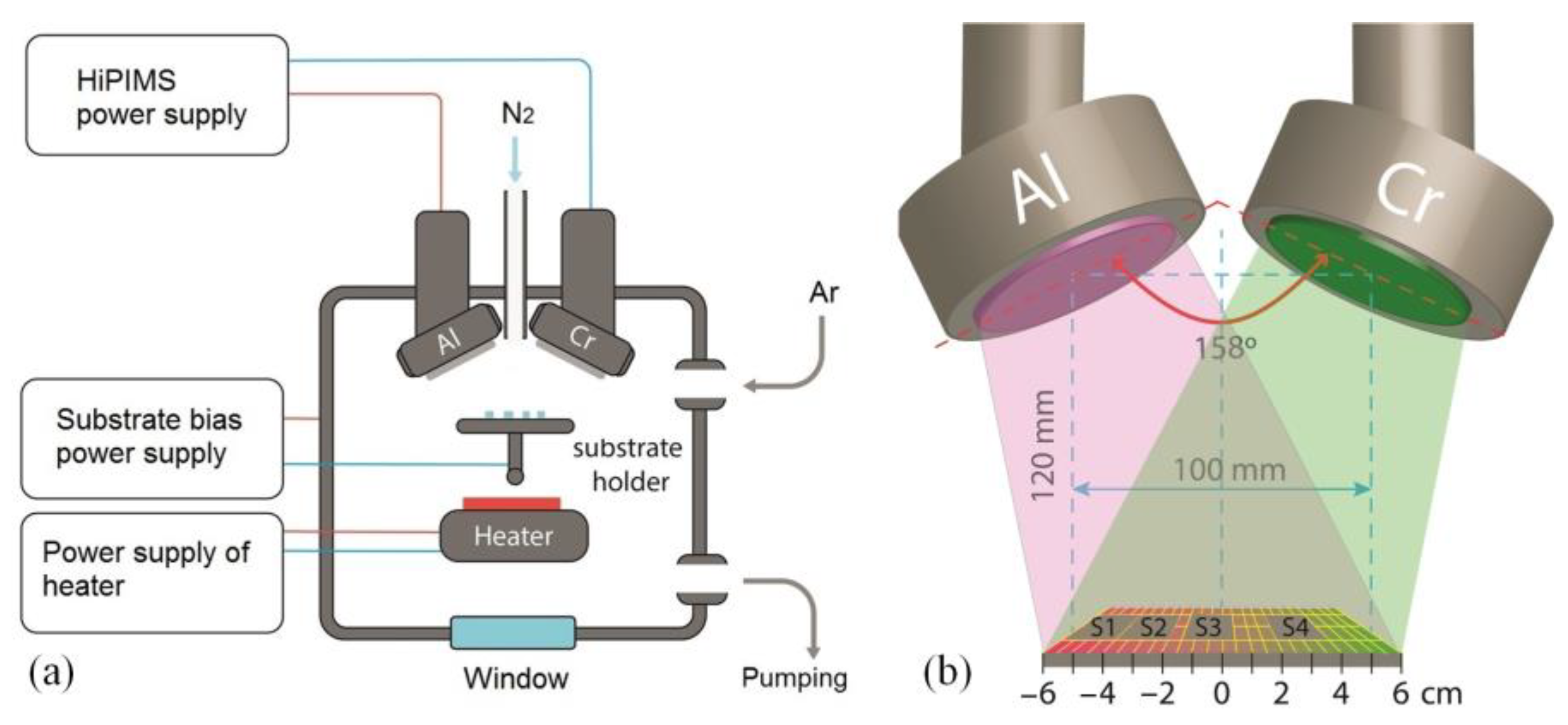
2.1. Preparation of (Cr1−xAlx)N Coatings

The coating was deposited onto 20 × 20 mm2 substrates 0.5 mm thick made of polished AISI 430 stainless steel. The surface roughness was 0.08 ± 0.01 μm. Prior to the coating deposition, the substrates were cleaned ultrasonically in isopropyl alcohol and acetone. In each liquid, the substrates were treated for 5 min.
A dual magnetron sputtering system with Al and Cr cathodes, both of 99.95% purity and a diameter 76 mm, was used for the coating deposition. The flow-chart of the proposed dual high-power impulse magnetron sputtering (dual-HiPIMS) vacuum system is illustrated in Figure 1 together with the arrangement of S1–S4 substrates on the holder relative to magnetrons. The working chamber was vacuumized by a turbo-molecular pump to a residual pressure of 8 × 10⁻³ Pa.
A ceramic infra-red heater provided the substrate heating up to 450 ± 10 °C, which was maintained during the coating deposition. The (Cr1−xAlx)N coating deposition was conducted in a mixture of argon and nitrogen at a total pressure of 0.1 Pa with the flow rates of 83 and 15 sccm, respectively. The magnetrons were powered by a single bipolar power supply, APEL-M-10HPP-1500 (“Applied Electronics”, Tomsk, Russia), that had the ability to independently adjust the parameters of positive and negative pulses [36]. This allowed us to independently control the power of each magnetron. The power supply was operated in power stabilization mode. The average discharge power Pd.avg was estimated as
P d . avg = 1 T 0 T U d I d d t
The operating discharge parameters included 5 kHz frequency, 20 µs pulse duration, and 0.5 kW and 1 kW power, respectively, for sputtering Cr and Al targets. The maximum voltages for Cr and Al magnetrons were 694 V and 677 V, and the maximum currents were 30 and 60 A, respectively. Values of nitrogen flow rate and magnetron powers had been determined in preliminary experiments. The power of the Cr magnetron was chosen to be half as high because the rate of CrN deposition is about twice as high as the rate of AlN deposition. To determine the optimal nitrogen flow rate, (Cr1−xAlx)N coatings were obtained at different nitrogen flow rates (11, 13, 15 and 18 sccm) at the same argon flow rate and magnetron powers. The coatings were obtained on samples placed in the center of the substrate holder, i.e., at the same distance from both magnetrons. Then, the hardness of these coatings was measured. The maximum coating hardness (25 GPa) was obtained with a nitrogen flow rate of 15 sccm. Therefore, further experiments were conducted at this nitrogen flow rate.
To improve the coating adhesive strength and provide its surface activation, the bipolar bias voltage with negative pulses of 800 V, 100 kHz and 70% duty cycle was supplied to the substrate for the first 5 min. The positive pulse amplitude ranged between 15 and 20% of the negative pulse amplitude. The deposition was conducted at 100 V negative pulse amplitude for 120 min. The coating thickness and the deposition rate were measured on an interference microscope, MII-4 (LOMO, St. Petersburg, Russia).

2.2. Surface Characterization

Determination of the elemental composition of the (Cr1−xAlx)N coating and wear scar observation was carried out with a Quanta 200 3D (FEI Company, Hillsboro, OR, USA) scanning electron microscope (SEM) coupled with an energy dispersive X-ray analyzer.
X-ray diffraction (XRD) patterns of the coatings were obtained using a Shimadzu XRD-6000 Diffractometer (Kyoto, Japan). Measurements were conducted using Cu Kα radiation in grazing-incidence X-ray diffraction geometry. Operating parameters for the XRD included 3.0° incidence angle, 20–80° scan range and 0.02° step angle. The analysis of the phase composition was performed using the PDF4+ database and the PowderCell 2.4 Rietveld program.
A NanoTest 600 hardness tester (Micro Materials Ltd., GB, Wrexham, UK) was used to measure the coating hardness by the Oliver and Pharr method [38]. The process parameters for the NanoTest 600 were 10 mN load, 20 s loading–unloading time, and 10 s maximum exposure time. Each substrate was indented 10 times, and the obtained results were averaged.
The tribological properties of the coatings were examined using the ball-on-disc method. Testing conditions included a 100 mm/s sliding speed, 2 N normal load applied to the steel (100Cr6) and ceramic (Al2O3) balls of the diameter 6 mm. Their physical and mechanical properties are given in Table 1. The wear track diameters for the steel and ceramic balls were 8 and 6 mm, respectively. At the end of the test, we measured the wear track profile with the interference MNP-2 (Russia) microscope-profilometer and the 130 (Zavod PROTON, Moscow, Russia) contact profilometer. The cross-sectional area of the wear track was calculated using the Origin 9 software. A Polar-1 metallographic microscope (Mikromed, Moscow, Russia) was used to examine the wear track in the reflected polarized light.
The wear volume is obtained from [39]:
V = π · ( R R 2 ( d / 2 ) 2 ) 2 · ( 2 R + R 2 ( d / 2 ) 2 ) 3
where R is the ball radius, and d is the wear track diameter. The wear rate results from the ratio between the wear volume for the disk/ball and the product of normal force by total sliding distance, viz. mm3·N−1·m−1.
A Rockwell-C scale hardness test conducted in accordance with the VDI 3198 standard [41] evaluated the adhesive strength of the coating. A TK-2 spheroconical diamond indenter (IvMashprom, Yekaterinburg, Russia) with a 120° included-cone angle was used for nanoindentation examinations. The full indentation load was 60 kg (588 N). The testing cycle continued for 2 s. After testing, the coating adhesion to the substrate ranged from perfect (HF1) to poor adhesion (HF6), depending on the number of cracks and delamination.

3. Results and Discussion

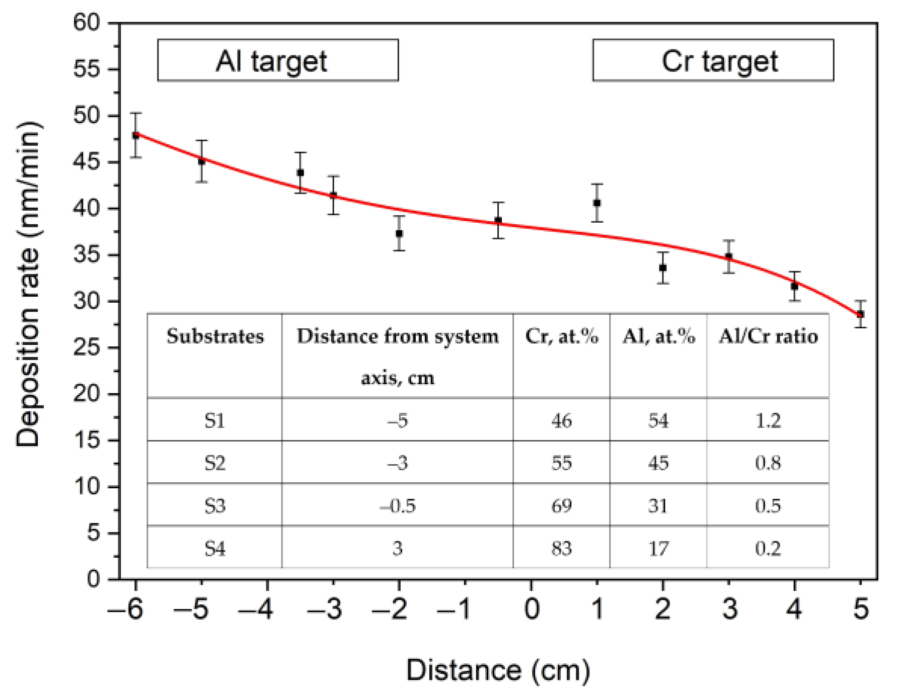
3.1. Chemical Composition

The rate of the (Cr1−xAlx)N coating deposition onto the stationary substrate depends on its position relative to magnetrons. Figure 2 presents the deposition rate distribution lengthwise over a glass substrate 11 cm long. Since the magnetron power with the Al target is 2 times higher than the magnetron power with the Cr target, the deposition rate near the former is maximum (48 ± 3 nm/min) and gradually lowers to 30 ± 2 nm/min as the Cr target approaches. These rates differ from each other by less than 2 times as aluminum has a much lower sputtering yield than chromium. The formation of the AlN insulating layer on the Al target surface during the reactive sputtering process reduces the sputtering yield of aluminum.
The results of the chemical analysis of substrates S1, S2, S3 and S4 arranged as presented in Figure 1b are summarized in a table in Figure 2. The Al content in the (Cr1−xAlx)N coating reduces from 54 at.% in substrate S1 to 17 at.% in substrate S4. The Al/Cr ratio grows by 6 times (from 0.2 to 1.2), depending on the substrate position. A small amount of oxygen (1–3 at.%) was also detected in the coatings.

3.2. Phase Composition of the (Cr1−xAlx)N Coating

The XRD patterns in Figure 3 obtained for the (Cr1−xAlx)N coating show that only peaks with (111), (200), (220) and (311) orientations matching the NaCl (B1) structure are present in substrate S4 (with the lowest Al content). This indicates that the crystal structure of the (Cr1−xAlx)N coating is mostly cubic, similar to the CrN coating structure.
Substrate S4 is characterized by the highly (111)-oriented structure. For the substrate S4, a slight shift of the peak (111) probably relates to the residual stress. A structural evolution is clearly observed with increasing Al content in this coating. The structure orientation fully changes to (220) orientation with increasing Al content from 17 to 31% and remains so at higher Al concentrations. The diffraction peak positions shift toward the larger-angle region, indicating a dissolution of added aluminum to the CrN lattice, which substitutes Cr atoms. In this case, the lattice parameter reduces from 0.4155 nm for substrate S4 to 0.4111 nm for substrate S1.
Banakh et al. [42] also reported on the preferred orientation (111) for the sputter-deposited (Cr1−xAlx)N coating with the low (x < 0.27) Al content. The preferred orientation (220) was observed for the coating with the higher Al content.

3.3. Mechanical Properties of the (Cr1−xAlx)N Coating

The block diagram in Figure 4a describes the hardness and elastic modulus of the (Cr1−xAlx)N coating depending on the substrate position and loading–unloading curves for this coating. Its thickness is over 2 µm and the maximum indentation depth is 110 nm (see Figure 4b), i.e., less than 10% of the coating thickness. In this case, the substrate does not significantly affect the hardness. With increasing Al content, the hardness and elastic modulus tend to grow. Thus, when the Al content increases from 17 to 54 at.%, the hardness grows from 17 to 28 GPa, and the elastic modulus increases from 173 to 318 GPa. The behavior of these two parameters can also be found in the literature [43,44]. The hardness is observed to grow with Al content increasing up to ~60 at.%. This can be explained by the strain-induced dissolution of Al atoms in the cubic lattice of the CrN coating, which hinders the dislocation movement [45]. When the Al content exceeds 63 at.%, the coating hardness lowers due to the formation of the hexagonal aluminum nitride (h-AlN).
As can be seen from Figure 4b, substrate S1 does not tend to creep during the pause running for 10 seconds as the displacement of the diamond indenter does not grow under the maximum constant load. At the same time, the coating low in aluminum manifests a creep as in the case with stainless steel substrates without the nitride coating [46].
Mechanical parameters of the (Cr1−xAlx)N coating calculated from nanoindentation are presented in Table 2. The resistance to plastic deformation H3/E2 and elastic recovery We of substrates S1, S2 and S3 reduce with decreasing Al content. No direct dependence is observed between the plasticity index H/E and the Al content. Although substrate S4 shows the highest plasticity index of ~0.1, its hardness is lower than that of other substrates. As shown in [47,48,49,50], the higher values of H/E and H3/E2 correlate with the high wear resistance of materials. It is thus possible to assume that the (Cr1−xAlx)N coating deposited on substrates S1 and S2 must possess the highest wear resistance.

3.4. Wear Resistance of (Cr1−xAlx)N/100Cr6 Sliding Pair

Tribology tests of the (Cr1−xAlx)N coating utilized steel (100Cr6) and ceramic (Al2O3) counter bodies of the diameter 6 mm. The wear rate was measured both for the coating and counter bodies. The block diagram in Figure 5 plots the results of the wear rate vs. the 100Cr6 counter body. One can see that the wear rate grows by 2 times with decreasing Al content, which correlates with the coating hardness reduction. The same dependence is observed in [51] for the (Cr1−xAlx)N/100Cr6 sliding pair. Nevertheless, all the substrates are characterized by the low wear rate of 10−9 mm3N−1m−1. As we assumed, substrates S1 and S2 have the lowest wear rate due to the high plasticity index and resistance to plastic deformation.
As noted in [2,52], one more parameter can fairly correctly predict the wear resistance of the substrate–coating system, namely the ratio Es/Ec between the elastic modulus of these system components. The highest wear resistance is observed when the ratio Es/Ec tends to unity. Huang et al. [2] show that the TiN coating demonstrates the highest wear resistance on Cu and M2 high-speed steel substrates. The TiN coating has a lower Es/Ec ratio (2.14 and 1.19 for Cu and M2, respectively) than the TiAlN coating (3.25 and 1.8 for Cu and M2, respectively). On the hard-alloy substrate WC–8 wt.% Co, the highest wear resistance belongs to the TiAlN coating with Es/Ec = 0.97, whereas for the TiN coating this ratio is 0.64. Łępicka et al. [46] confirm the correctness of using the Es/Ec ratio to predict the coating wear resistance. They report that the TiN coating on the 316LVM stainless steel (Es/Ec = 1.8) manifests a higher wear resistance than this coating on the Ti6Al4V alloy (Es/Ec = 3.06).
The elastic modulus of AISI 430 steel is 182 GPa. The ratio Es/Ec therefore reduces from 1.75 (for substrate S1) to 0.95 (for substrate S4), depending on the (Cr1−xAlx)N coating composition. Substrate S4 must possess the highest wear resistance, but our experiment shows that it lowers with decreasing Es/Ec ratio. This is probably associated with the counter body material. According to Table 1, the 100Cr6 steel ball has low hardness and resistance to plastic deformation, which leads to its intensive wear at a rate of ~2 × 10⁻⁵ mm3N−1m−1, as illustrated in Figure 5. Thus, in the case of the hard (Cr1−xAlx)N/soft 100Cr6 sliding pair, the ratio Es/Ec does not enable correct prediction of the wear resistance of hard nitride coatings.
Figure 6 contains SEM images of wear scars on the 100Cr6 ball surface. For all (Cr1−xAlx)N coatings, significant wear of the 100Cr6 ball surface is observed. The wear scar diameter ranges within 1200 and 1250 µm and weakly depends on the coating composition. One can see unidirectional scratches relative to sliding of the coating material particles.
In Figure 7, one can see wear tracks on the (Cr1−xAlx)N coating surface.
These tracks are produced by the particles of the counter body material smeared on the coating surface. The surface wear occurs by the adhesion mechanism. Wear tracks left by the steel counter body during friction on substrates S1–S4 are characterized by regions high in iron. Shallow grooves left by the material particles of the worn counter body are observed on substrate S4. This material reacts with oxygen and generates harder oxide particles.
The presence of iron and oxygen in the wear tracks is confirmed by the EDX analysis presented in Figure 8. Maps of the element distribution show that oxygen locates together with iron. This fact confirms oxidation of the worn material during tribochemical wear. The same is observed in [46,52] for the TiN coating during tribology testing.

3.5. Wear Resistance of (Cr1−xAlx)N/Al2O3 Sliding Pair

The block diagram in Figure 9 plots the results of the wear rate vs. the Al2O3 counter body. In this case, the wear rate increases by two orders of magnitude and is 10−7 mm3N−1m−1. The wear resistance tends to grow from 5.3 × 10⁻⁷ to 3.9 × 10⁻⁷ mm3N−1m−1 with decreasing Al content in the coating. This is because the harder coating on substrates S1 and S2 provides stronger wear of the counter body, and hard abrasive particles removed from the coating surface intensify its wear. The wear rate of the ceramic counter body on substrate S1 is 9.4 × 10⁻⁸ mm3N−1m−1, whereas on substrate S4 it reduces down to 2.8 × 10⁻⁸ mm3N−1m−1.
SEM images of wear scars in Figure 10 depict the surface of the ceramic ball in the (Cr1−xAlx)N/Al2O3 sliding pair. One can see that the wear scar diameter on the ceramic ball is four or five times smaller than on the steel ball. The highest wear is observed for substrate S1, when the coating hardness is comparable to that of the counter body. The lower the Al content in the (Cr1−xAlx)N coating, the lower the substrate hardness and wear scar diameter on the counter body surface.
As can be seen from SEM images in Figure 11, the wear scars on the (Cr1−xAlx)N coating surface appear after the abrasive wear. It should be noted that all the substrates S1–S4 have a low wear rate regardless of the coating hardness.

3.6. Friction Coefficient of the (Cr1−xAlx)N Coating

Friction curves of the (Cr1−xAlx)N coating measured with 100Cr6 and Al2O3 counter bodies are shown in Figure 12. In the case with the steel counter body, the friction coefficient does not clearly depend on the coating composition. The jumps observed for the friction coefficient for all the substrates can be associated with the transfer of the counter body material to the coating surface. The smeared material increases the friction coefficient. The correlation of the friction and abrasive wear with the coating composition can be determined by tribology tests with the use of the Al2O3 counter body. After a short running-in phase of ~15 m, the friction coefficient stabilizes at 0.43 for the coating low in Al and having the lowest wear rate (substrate S4). The running-in phase for the coating high in Al and having the highest wear rate (substrate S1) is much longer (~60 m) and the friction coefficient is higher (0.63).
Table 3 presents the literature data on mechanical and tribological properties of magnetron-sputter-deposited CrAlN coating. Among the coatings obtained by different types of magnetron sputtering, our coating synthesized by short-pulse high-power dual magnetron sputtering has a comparable hardness to other coatings, the highest wear resistance, and the lowest friction coefficient.
Arc-evaporated AlCrN coatings [56] in ball-on-disc experiments against Al2O3 demonstrated lower wear rate (about 2 × 10⁻⁷ mm3N−1m−1), but a comparable coefficient of friction (0.63).

3.7. Adhesive Strength Measurement

The VDI 3198 Rockwell-C indentation test is often used to evaluate coating adhesion to different substrates [57,58,59]. After indentation, localized plastic deformation occurs near indentation scars, which can cause the coating to fracture. Depending on the fracture type (cracks, laminations, swelling) and size, the damage is classified according to the VDI 3198 standard from HF1 to HF4, where insignificant microcracks and delaminations of the coating near indentation scars are considered as allowable for practical use. HF5 and HF6 indicate unacceptable adhesion with severe delamination around the indentation scar [41]. Rockwell indentation images in Figure 13 describe the respective substrates. One can see microcracks after indentation on substrates S1 and S2 with the hardest coating. Since hard coating is more brittle, plastic deformation induces its cracking. The harder the coating, the longer the microcracks. In general, coatings on substrates S1 and S2 possess good adhesive strength and satisfy HF1 and HF2 strength quality.
Coatings on substrates S3 and S4 possess lower hardness, and no damages are observed near indentation scars. The adhesion of the coating on these substrates is good and satisfies the HF1 strength quality. Thus, the decrease in the Al content in the (Cr1−xAlx)N coating results in its hardness reduction, but improves the adhesive strength.

4. Conclusions

The (Cr1−xAlx)N coatings with 17 to 54 at.% Al content were deposited onto steel substrates by short-pulse high-power dual magnetron sputtering of Al and Cr targets at a substrate bias voltage. It was demonstrated that the lower Al content in the (Cr1−xAlx)N coating led to its hardness reduction from 28 to 16 GPa. In tribology testing, the (Cr1−xAlx)N/100Cr6 sliding pair showed tribochemical wear accompanied by the dominant wear of the counter body, its smearing on the coating surface and oxidation during friction. The (Cr1−xAlx)N/Al2O3 sliding pair showed abrasive wear of the surface induced by hard particles of the coating and the counter body. In tribology testing with the ceramic counter body, the (Cr1−xAlx)N coating possessing lower hardness manifested a lower wear rate due to the less worn counter body and, consequently, a smaller quantity of abrasive particles involved in the friction process. According to the Rockwell-C scale hardness test, the HF1 and HF2 adhesive strength qualities of (Cr1−xAlx)N coatings with 54 and 45 at.% Al content and high hardness defined their strong interfacial adhesion, whereas the coatings with 31 and 17 at.% Al content and lower hardness showed the adhesive strength quality HF1. In general, (Cr1−xAlx)N coatings possessed good adhesive strength and satisfied industry standards.
In this work, the (Cr1−xAlx)N coating was used to demonstrate the advantages of short-pulse high-power dual magnetron sputtering, which can be used to synthesize various hard and wear-resistant coatings based on Ti, Cr, Al and B elements. This will be discussed in our further research.

Author Contributions

Conceptualization, A.G., V.O., A.S.; Data curation, A.G., V.O., A.S.; Formal analysis, A.Z., K.O.; Investigation, A.G., K.O., A.Z.; Methodology, A.G.; Project administration, A.S.; Resources, A.S., V.O..; Writing—original draft, A.G., A.Z.; Writing—review & editing, A.G., A.S., K.O., V.O., A.Z. All authors have read and agreed to the published version of the manuscript.

Funding

This work was supported by the Ministry of Science and Higher Education of the Russian Federation (Project No. 075-15-2021-1348, event No. 2.1.3).

Institutional Review Board Statement

Not applicable.

Informed Consent Statement

Not applicable.

Acknowledgments

The authors would like to express their gratitude towards the management of the Materials Science Core Facility Centre of National Research Tomsk State University for the Quanta 200 3D dual beam system and XRD-6000 diffractometer employed in these studies. The authors also thank the management of Tomsk Regional Core Facility Centre of the Research Center of Tomsk for the NanoTest 600 hardness tester employed in these studies.

Conflicts of Interest

The authors declare no conflict of interest.

References

  1. Das, S.; Guha, S.; Ghadai, R.; Swain, B.P. A comparative analysis over different properties of TiN, TiAlN and TiAlSiN thin film coatings grown in nitrogen gas atmosphere. Mater. Chem. Phys. 2021, 258, 123866. [Google Scholar] [CrossRef]
  2. Huang, X.; Etsion, I.; Shao, T. Effects of elastic modulus mismatch between coating and substrate on the friction and wear properties of TiN and TiAlN coating systems. Wear 2015, 338–339, 54–61. [Google Scholar] [CrossRef]
  3. Tlili, B.; Mustapha, N.; Nouveau, C.; Benlatreche, Y.; Guillemot, G.; Lambertin, M. Correlation between thermal properties and aluminum fractions in CrAlN layers deposited by PVD technique. Vacuum 2010, 84, 1067–1074. [Google Scholar] [CrossRef] [Green Version]
  4. Chim, Y.C.; Ding, X.Z.; Zeng, X.T.; Zhang, S. Oxidation resistance of TiN, CrN, TiAlN and CrAlN coatings deposited by lateral rotating cathode arc. Thin Solid Film. 2009, 517, 4845–4849. [Google Scholar] [CrossRef]
  5. Polcar, T.; Cavaleiro, A. High temperature properties of CrAlN, CrAlSiN and AlCrSiN coatings—Structure and oxidation. Mater. Chem. Phys. 2011, 129, 195–201. [Google Scholar] [CrossRef]
  6. Hu, C.; Xu, Y.X.; Chen, L.; Pei, F.; Du, Y. Mechanical properties, thermal stability and oxidation resistance of Ta-doped CrAlN coatings. Surf. Coat. Technol. 2019, 368, 25–32. [Google Scholar] [CrossRef]
  7. Fan, Q.X.; Zhang, J.J.; Wu, Z.H.; Liu, Y.M.; Zhang, T.; Yan, B.; Wang, T.G. Influence of Al Content on the Microstructure and Properties of the CrAlN Coatings Deposited by Arc Ion Plating. Acta Metall. Sin. (Engl. Lett.) 2017, 30, 1221–1230. [Google Scholar] [CrossRef]
  8. Kang, M.C.; Je, S.K.; Kim, K.H.; Shin, B.S.; Kwon, D.H.; Kim, J.S. Cutting performance of CrN-based coatings tool deposited by hybrid coating method for micro drilling applications. Surf. Coat. Technol. 2008, 202, 5629–5632. [Google Scholar] [CrossRef]
  9. Romero, J.; Gómez, M.A.; Esteve, J.; Montalà, F.; Carreras, L.; Grifol, M.; Lousa, A. CrAlN coatings deposited by cathodic arc evaporation at different substrate bias. Thin Solid Film. 2006, 515, 113–117. [Google Scholar] [CrossRef]
  10. Li, M.; Wang, F. Effects of nitrogen partial pressure and pulse bias voltage on (Ti,Al)N coatings by arc ion plating. Surf. Coat. Technol. 2003, 167, 197–202. [Google Scholar] [CrossRef]
  11. Alhafian, M.-R.; Chemin, J.-B.; Fleming, Y.; Bourgeois, L.; Penoy, M.; Useldinger, R.; Soldera, F.; Mücklich, F.; Choquet, P. Comparison on the structural, mechanical and tribological properties of TiAlN coatings deposited by HiPIMS and Cathodic Arc Evaporation. Surf. Coat. Technol. 2021, 423, 127529. [Google Scholar] [CrossRef]
  12. Zhao, Y.; Lin, G.; Xiao, J.; Lang, W.; Dong, C.; Gong, J.; Sun, C. Synthesis of titanium nitride thin films deposited by a new shielded arc ion plating. Appl. Surf. Sci. 2011, 257, 5694–5697. [Google Scholar] [CrossRef]
  13. Chunyan, Y.; Linhai, T.; Yinghui, W.; Shebin, W.; Tianbao, L.; Bingshe, X. The effect of substrate bias voltages on impact resistance of CrAlN coatings deposited by modified ion beam enhanced magnetron sputtering. Appl. Surf. Sci. 2009, 255, 4033–4038. [Google Scholar] [CrossRef]
  14. Mohammadpour, E.; Jiang, Z.T.; Altarawneh, M.; Xie, Z.; Zhou, Z.; Mondinos, N.; Kimpton, J.; Dlugogorski, B.Z. Predicting high temperature mechanical properties of CrN and CrAlN coatings from in-situ synchrotron radiation X-ray diffraction. Thin Solid Film. 2016, 599, 98–103. [Google Scholar] [CrossRef] [Green Version]
  15. Ding, X.Z.; Zeng, X.T. Structural, mechanical and tribological properties of CrAlN coatings deposited by reactive unbalanced magnetron sputtering. Surf. Coat. Technol. 2005, 200, 1372–1376. [Google Scholar] [CrossRef]
  16. Drnovšek, A.; Vo, H.T.; Rebelo de Figueiredo, M.; Kolozsvári, S.; Hosemann, P.; Franz, R. High temperature fracture toughness of single-layer CrAlN and CrAlSiN hard coatings. Surf. Coat. Technol. 2021, 409, 126909. [Google Scholar] [CrossRef]
  17. Tillmann, W.; Hagen, L.; Stangier, D.; Dias, N.F.L.; Görtz, J.; Kensy, M.D. Lapping and polishing of additively manufactured 316L substrates and their effects on the microstructural evolution and adhesion of PVD CrAlN coatings. Surf. Coat. Technol. 2021, 428, 127905. [Google Scholar] [CrossRef]
  18. Kitamika, Y.; Hasegawa, H. Mechanical, tribological, and oxidation properties of Si-containing CrAlN films. Vacuum 2019, 164, 29–33. [Google Scholar] [CrossRef]
  19. Nouveau, C.; Labidi, C.; Ferreira Martin, J.-P.; Collet, R.; Djouadi, A. Application of CrAlN coatings on carbide substrates in routing of MDF. Wear 2007, 263, 1291–1299. [Google Scholar] [CrossRef] [Green Version]
  20. Bai, Y.; Xi, Y.; Gao, K.; Yang, H.; Pang, X.; Volinsky, A.A. Residual stress control in CrAlN coatings deposited on Ti alloys. Ceram. Int. 2018, 44, 4653–4659. [Google Scholar] [CrossRef]
  21. Barshilia, H.C.; Selvakumar, N.; Deepthi, B.; Rajam, K.S. A comparative study of reactive direct current magnetron sputtered CrAlN and CrN coatings. Surf. Coat. Technol. 2006, 201, 2193–2201. [Google Scholar] [CrossRef]
  22. Xingrun, R.; Zhu, H.; Meixia, L.; Jiangao, Y.; Hao, C. Comparison of Microstructure and Tribological Behaviors of CrAlN and CrN Film Deposited by DC Magnetron Sputtering. Rare Metal Mat. Eng. 2018, 47, 1100–1106. [Google Scholar] [CrossRef]
  23. Hsiao, Y.C.; Lee, J.W.; Yang, Y.C.; Lou, B.S. Effects of duty cycle and pulse frequency on the fabrication of AlCrN thin films deposited by high power impulse magnetron sputtering. Thin Solid Film. 2013, 549, 281–291. [Google Scholar] [CrossRef]
  24. Liu, L.; Ruan, Q.; Wu, Z.; Li, D.; Huang, C.; Wu, Y.; Li, T.; Wu, Z.; Tian, X.; Fu, R.K.Y.; et al. Fabrication and cutting performance of CrAlN/CrAl multilayer coatings deposited by continuous high-power magnetron sputtering. Ceram. Int. 2022, 48, 14528–14536. [Google Scholar] [CrossRef]
  25. Gui, B.; Zhou, H.; Zheng, J.; Liu, X.; Feng, X.; Zhang, Y.; Yang, L. Microstructure and properties of TiAlCrN ceramic coatings deposited by hybrid HiPIMS/DC magnetron co-sputtering. Ceram. Int. 2021, 47, 8175–8183. [Google Scholar] [CrossRef]
  26. Rojas, T.C.; Caro, A.; Lozano, G.; Sánchez-López, J.C. High-temperature solar-selective coatings based on Cr(Al)N. Part 1: Microstructure and optical properties of CrNy and Cr1-xAlxNy films prepared by DC/HiPIMS. Sol. Energy Mater. Sol. Cells 2021, 223, 110951. [Google Scholar] [CrossRef]
  27. Lattemann, M.; Ehiasarian, A.P.; Bohlmark, J.; Persson, P.Å.O.; Helmersson, U. Investigation of high power impulse magnetron sputtering pretreated interfaces for adhesion enhancement of hard coatings on steel. Surf. Coat. Technol. 2006, 200, 6495–6499. [Google Scholar] [CrossRef] [Green Version]
  28. Sarakinos, K.; Alami, J.; Konstantinidis, S. High power pulsed magnetron sputtering: A review on scientific and engineering state of the art. Surf. Coat. Technol. 2010, 204, 1661–1684. [Google Scholar] [CrossRef]
  29. Drnovšek, A.; Rebelo de Figueiredo, M.; Vo, H.; Xia, A.; Vachhani, S.J.; Kolozsvári, S.; Hosemann, P.; Franz, R. Correlating high temperature mechanical and tribological properties of CrAlN and CrAlSiN hard coatings. Surf. Coat. Technol. 2019, 372, 361–368. [Google Scholar] [CrossRef]
  30. Li, W.; Zheng, K.; Liu, P.; Zhu, P.; Zhang, K.; Ma, F.; Liu, X.; Chen, X.; He, D. Microstructure and superhardness effect of CrAlN/SiO2 nanomultilayered film synthesized by reactive magnetron sputtering. Mater. Charact. 2016, 118, 79–84. [Google Scholar] [CrossRef]
  31. Weirather, T.; Czettl, C.; Polcik, P.; Kathrein, M.; Mitterer, C. Industrial-scale sputter deposition of Cr1−xAlxN coatings with 0.21 ≤ x ≤ 0.74 from segmented targets. Surf. Coat. Technol. 2013, 232, 303–310. [Google Scholar] [CrossRef]
  32. Bagcivan, N.; Bobzin, K.; Theiß, S. (Cr1−xAlx)N: A comparison of direct current, middle frequency pulsed and high power pulsed magnetron sputtering for injection molding components. Thin Solid Film. 2013, 528, 180–186. [Google Scholar] [CrossRef]
  33. PalDey, S.; Deevi, S.C. Single layer and multilayer wear resistant coatings of (Ti, Al)N: A review. Mater. Sci. Eng. A 2003, 342, 58–79. [Google Scholar] [CrossRef]
  34. Gibson, D.R.; Brinkley, I.; Waddell, E.M.; Walls, J.M. Closed field magnetron sputtering: New generation sputtering process for optical coatings. In Proceedings of the SPIE 7101 Advances in Optical Thin Films III, Glasgow, UK, 2–5 September 2008; Volume 7101, p. 710108. [Google Scholar] [CrossRef]
  35. Oskirko, V.O.; Zakharov, A.N.; Pavlov, A.P.; Solovyev, A.A.; Semenov, V.A.; Rabotkin, S.V. Hybrid HIPIMS+MFMS power supply for dual magnetron sputtering systems. Vacuum 2020, 181, 109670. [Google Scholar] [CrossRef]
  36. Oskirko, V.O.; Zakharov, A.N.; Semenov, V.A.; Pavlov, A.P.; Grenadyorov, A.S.; Rabotkin, S.V.; Solovyev, A.A. Short-pulse high-power dual magnetron sputtering. Vacuum 2022, 200, 111026. [Google Scholar] [CrossRef]
  37. Tiron, V.; Velicu, I.L.; Cristea, D.; Lupu, N.; Stoian, G.; Munteanu, D. Influence of ion-to-neutral flux ratio on the mechanical and tribological properties of TiN coatings deposited by HiPIMS. Surf. Coat. Technol. 2018, 352, 690–698. [Google Scholar] [CrossRef]
  38. Oliver, W.C.; Pharr, G.M. Measurement of hardness and elastic modulus by instrumented indentation: Advances in understanding and refinements to methodology. J. Mater. Res. 2004, 19, 3–20. [Google Scholar] [CrossRef]
  39. Liang, Q.; Stanishevsky, A.; Vohra, Y.K. Tribological properties of undoped and boron-doped nanocrystalline diamond films. Thin Solid Film. 2008, 517, 800–804. [Google Scholar] [CrossRef] [Green Version]
  40. Ramadoss, R.; Kumar, N.; Pandian, R.; Dash, S.; Ravindran, T.R.; Arivuoli, D.; Tyagi, A.K. Tribological properties and deformation mechanism of TiAlN coating sliding with various counterbodies. Tribol. Int. 2013, 66, 143–149. [Google Scholar] [CrossRef]
  41. Vidakis, N.; Antoniadis, A.; Bilalis, N. The VDI 3198 indentation test evaluation of a reliable qualitative control for layeredcompounds. J. Mater. Process. Technol. 2003, 143–144, 481–485. [Google Scholar] [CrossRef]
  42. Banakh, O.; Schmid, P.E.; Sanjines, R.; Levy, F. High-temperature oxidation resistance of Cr1-xAlxN thin films deposited by reactive magnetron sputtering. Surf. Coat. Technol. 2003, 163–164, 57–61. [Google Scholar] [CrossRef]
  43. Kawate, M.; Kimura Hashimoto, A.; Suzuki, T. Oxidation resistance of Cr1−XAlXN and Ti1−XAlXN films. Surf. Coat. Technol. 2003, 165, 163–167. [Google Scholar] [CrossRef]
  44. Kimura, A.; Kawate, M.; Hasegawa, H.; Suzuki, T. Anisotropic lattice expansion and shrinkage of hexagonal TiAlN and CrAlN films. Surf. Coat. Technol. 2003, 169–170, 367–370. [Google Scholar] [CrossRef]
  45. Hirai, M.; Ueno, Y.; Suzuki, T.; Jiang, W.; Grigoriu, C.; Yatsui, K. Characteristics of (Cr1-x, Alx)N Films Prepared by Pulsed Laser Deposition. Jpn. J. Appl. Phys. 2001, 40, 1056–1060. [Google Scholar] [CrossRef]
  46. Łępicka, M.; Grądzka-Dahlke, M.; Pieniak, D.; Pasierbiewicz, K.; Kryńska, K.; Niewczas, A. Tribological performance of titanium nitride coatings: A comparative study on TiN-coated stainless steel and titanium alloy. Wear 2019, 422–423, 68–80. [Google Scholar] [CrossRef]
  47. Cai, J.B.; Wang, X.L.; Bai, W.Q.; Zhao, X.Y.; Wang, T.Q.; Tu, J.P. Bias-graded deposition and tribological properties of Ti-contained a-C gradient composite film on Ti6Al4V alloy. Appl. Surf. Sci. 2013, 279, 450–457. [Google Scholar] [CrossRef]
  48. Mo, J.L.; Zhu, M.H.; Leyland, A.; Matthews, A. Impact wear and abrasion resistance of CrN, AlCrN and AlTiN PVD coatings. Surf. Coat. Technol. 2013, 215, 170–177. [Google Scholar] [CrossRef]
  49. Krysina, O.V.; Prokopenko, N.A.; Ivanov, Y.F.; Tolkachev, O.S.; Shugurov, V.V.; Petrikova, E.A. Multi-layered gradient (Zr,Nb)N coatings deposited by the vacuum-arc method. Surf. Coat. Technol. 2020, 393, 125759. [Google Scholar] [CrossRef]
  50. Zok, F.W.; Miserez, A. Property maps for abrasion resistance of materials. Acta Mater. 2007, 55, 6365–6371. [Google Scholar] [CrossRef]
  51. Reiter, A.E.; Derflinger, V.H.; Hanselmann, B.; Bachmann, T.; Sartory, B. Investigation of the properties of Al1-xCrxN coatings prepared by cathodic arc evaporation. Surf. Coat. Technol. 2005, 200, 2114–2122. [Google Scholar] [CrossRef]
  52. Łępicka, M.; Grądzka-Dahlke, M.; Pieniak, D.; Pasierbiewicz, K.; Niewczas, A. Effect of mechanical properties of substrate and coating on wear performance of TiN- or DLC-coated 316LVM stainless steel. Wear 2017, 382–383, 62–70. [Google Scholar] [CrossRef]
  53. Sánchez-López, J.C.; Contreras, A.; Domínguez-Meister, S.; García-Luis, A.; Brizuela, M. Tribological behaviour at high temperature of hard CrAlN coatings doped with Y or Zr. Thin Solid Film. 2014, 550, 413–420. [Google Scholar] [CrossRef] [Green Version]
  54. Lin, J.; Mishra, B.; Moore, J.J.; Sproul, W.D.; Rees, J.A. Effects of the substrate to chamber wall distance on the structure and properties of CrAlN films deposited by pulsed closed field unbalanced magnetron sputtering (P-CFUBMS). Surf. Coat. Technol. 2007, 201, 6960–6969. [Google Scholar] [CrossRef]
  55. Sidelev, D.V.; Voronina, E.D.; Kashkarov, E.B. Duplex treatment of AISI 420 steel by RF-ICP nitriding and CrAlN coating deposition: The role of nitriding duration. Coatings 2022, 12, 1709. [Google Scholar] [CrossRef]
  56. Reiter, A.E.; Mitterer, C.; Rebelo de Figueiredo, M.; Franz, R. Abrasive and adhesive wear behavior of arc-evaporated Al1-xCrxN hard coatings. Tribol. Lett. 2010, 37, 605–611. [Google Scholar] [CrossRef]
  57. Falsafein, M.; Ashrafizadeh, F.; Kheirandish, A. Influence of thickness on adhesion of nanostructured multilayer CrN/CrAlN coatings to stainless steel substrate. Surf. Interfaces 2018, 13, 178–185. [Google Scholar] [CrossRef]
  58. Heinke, W.; Leyland, A.; Matthews, A.; Berg, G.; Friedrich, C.; Broszeit, E. Evaluation of PVD nitride coatings, using impact, scratch and Rockwell-C adhesion tests. Thin Solid Film. 1995, 270, 431–438. [Google Scholar] [CrossRef]
  59. Zhang, X.; Tian, X.; Gong, C.; Liu, X.; Li, J.; Zhu, J.; Lin, H. Effect of plasma nitriding ion current density on tribological properties of composite CrAlN coatings. Ceram. Int. 2022, 48, 3954–3962. [Google Scholar] [CrossRef]
Figure 1. (a) Flow-chart of the proposed dual-HiPIMS vacuum system and (b) arrangement of S1–S4 substrates on the holder relative to magnetrons.
Materials 15 08237 g001
Figure 2. Lengthwise distribution of (Cr1−xAlx)N coating deposition rate on substrate holder. Table: elemental composition of (Cr1−xAlx)N coating.
Materials 15 08237 g002
Figure 3. XRD patterns of (Cr1−xAlx)N coatings.
Materials 15 08237 g003
Figure 4. (a) Hardness, elastic modulus and (b) loading–unloading curves obtained for (Cr1−xAlx)N coating after nanoindentation measurement.
Materials 15 08237 g004
Figure 5. Wear rate of (Cr1−xAlx)N coating and counter body for (Cr1−xAlx)N/100Cr6 sliding pair.
Materials 15 08237 g005
Figure 6. Wear scars on the 100Cr6 ball surface for substrates: (a) S1 (Al/Cr = 1.2), (b) S2 (Al/Cr = 0.8), (c) S3 (Al/Cr = 0.5), (d) S4 (Al/Cr = 0.2).
Materials 15 08237 g006
Figure 7. Wear tracks on the surface produced by the 100Cr6 counter body for substrates: (a) S1 (Al/Cr = 1.2), (b) S2 (Al/Cr = 0.8), (c) S3 (Al/Cr = 0.5), (d) S4 (Al/Cr = 0.2).
Materials 15 08237 g007
Figure 8. SEM images of wear tracks and distribution of chromium, iron and oxygen in coatings: (a) S1 (Al/Cr = 1.2), (b) S2 (Al/Cr = 0.8), (c) S3 (Al/Cr = 0.5), (d) S4 (Al/Cr = 0.2).
Materials 15 08237 g008
Figure 9. Wear rate of (Cr1−xAlx)N coating and counter body for (Cr1−xAlx)N/Al2O3 sliding pair.
Materials 15 08237 g009
Figure 10. Wear scars on the Al2O3 ball surface for substrates: (a) S1 (Al/Cr = 1.2), (b) S2 (Al/Cr = 0.8), (c) S3 (Al/Cr = 0.5), (d) S4 (Al/Cr = 0.2).
Materials 15 08237 g010
Figure 11. Wear tracks on the surface produced by Al2O3 counter body for substrates: (a) S1 (Al/Cr = 1.2), (b) S2 (Al/Cr = 0.8), (c) S3 (Al/Cr = 0.5), (d) S4 (Al/Cr = 0.2).
Materials 15 08237 g011
Figure 12. Coefficient of friction as a function of sliding distance measured by ball-on-disc method: (a) 100Cr6, (b) Al2O3 counter bodies on the (Cr1−xAlx)N coating.
Materials 15 08237 g012
Figure 13. Rockwell indentation images of substrates: (a) S1 (Al/Cr = 1.2), (b) S2 (Al/Cr = 0.8), (c) S3 (Al/Cr = 0.5), (d) S4 (Al/Cr = 0.2).
Materials 15 08237 g013
Table 1. Physical and mechanical properties of counter bodies [40] and substrate.
Counter BodyH, GPaE, GPaδ, g∙cm−3υ, a.u.H3/E2, MPa
100Cr62.7 ± 0.2185 ± 177.80.300.57
Al2O326 ± 2.3382 ± 323.90.24120.4
Substrate2.5 ± 0.1182 ± 77.7-0.47
Notation: H—hardness, E—elastic modulus, δ—density, υ—Poisson’s ratio.
Table 2. Mechanical parameters of the (Cr1−xAlx)N coating.
SubstratesH, GPaE, GPaH/EH3/E2, MPaWe, %
S1283180.08821989.1
S2252840.08919888.5
S3202710.07511574.1
S4171730.09515083.4
Table 3. Mechanical and tribological properties of magnetron-sputter-deposited CrAlN coating.
MethodsSubstrateAl/Cr RatioHardness
(GPa)
Wear Rate
(mm3N−1m−1)
COF (a.u.)Counter BodiesLiterature
RF sputteringSi, stainless steel1.430.9-0.4–0.8SiC[18]
DC sputteringAISI 304--3.7 × 10−60.4–0.9Si3N4[22]
DC sputteringM2 HSS128-0.57Al2O3[53]
C-HPMSSi, cemented carbide -35.6-0.76Si3N4[24]
HiPIMS/DC co-sputtering9Cr18 stainless steel1.320.78 × 10−70.5Al2O3[25]
CFUMSHigh speed steel0.2236 × 10−7-Al2O3[15]
CFUMSAISI 3040.427.43.69 × 10−60.41WC-Co (6%)[54]
MF MS *AISI 4202234 × 10−6-Al2O3[55]
Short-pulse dual HiPIMSAISI 430 1.2285.3 × 10−70.6–0.63Al2O3Our work
0.2173.9 × 10−70.42–0.45
* MF MS—middle-frequency magnetron sputtering.
Publisher’s Note: MDPI stays neutral with regard to jurisdictional claims in published maps and institutional affiliations.

