
The Effects of Core Machining Configurations on the Mechanical Properties of Cores and Sandwich Structures

 ,
,
Abstract
:1. Introduction
2. Experiment
2.1. Materials
2.2. Specimens and Manufacturing
2.2.1. Core Machining Configurations
2.2.2. Specimen Design
2.2.3. Specimen Manufacturing
2.3. Test Setups and Apparatuses
3. Results and Analysis
3.1. Compressive Test
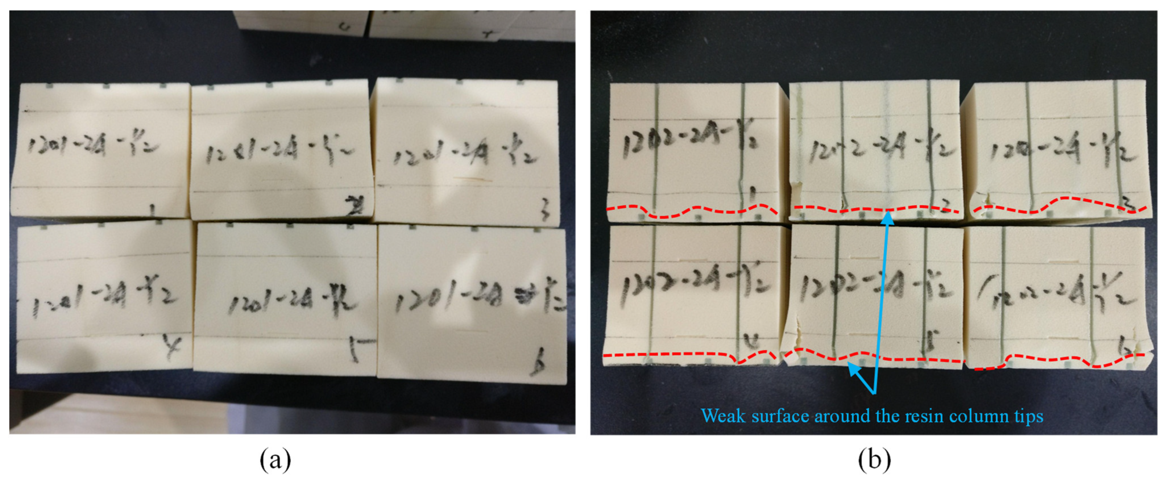
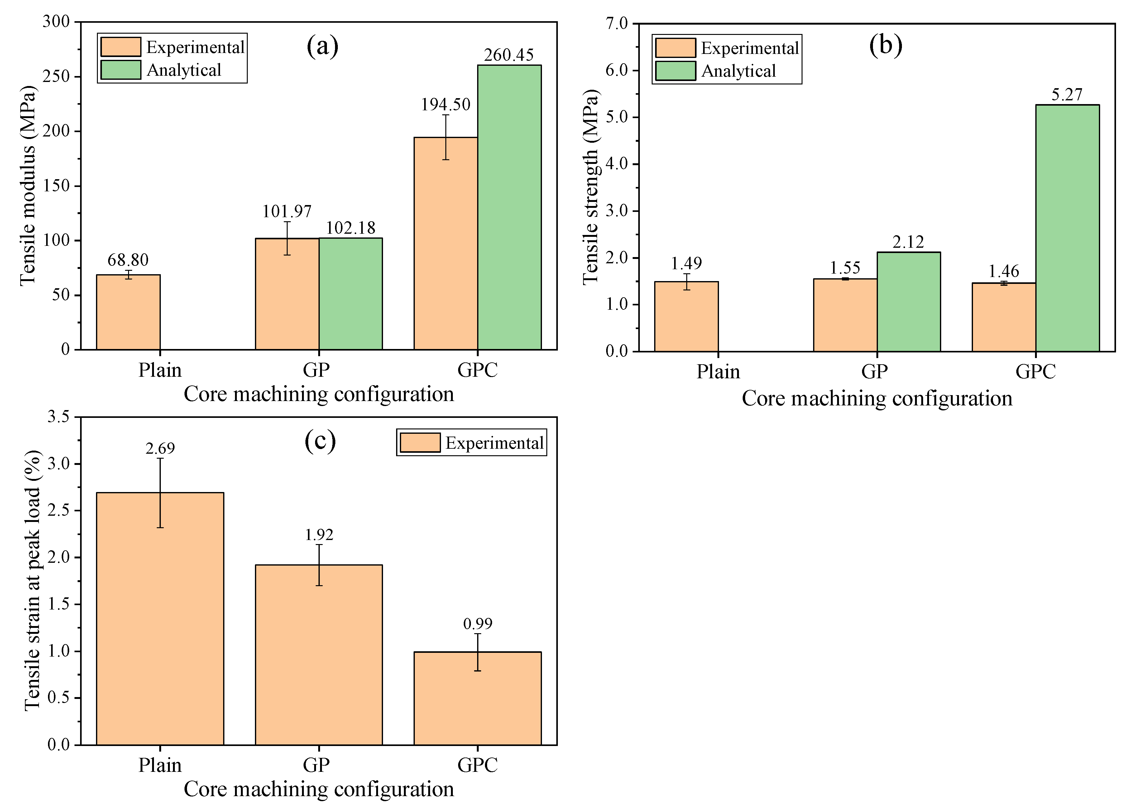
3.2. Tensile Test
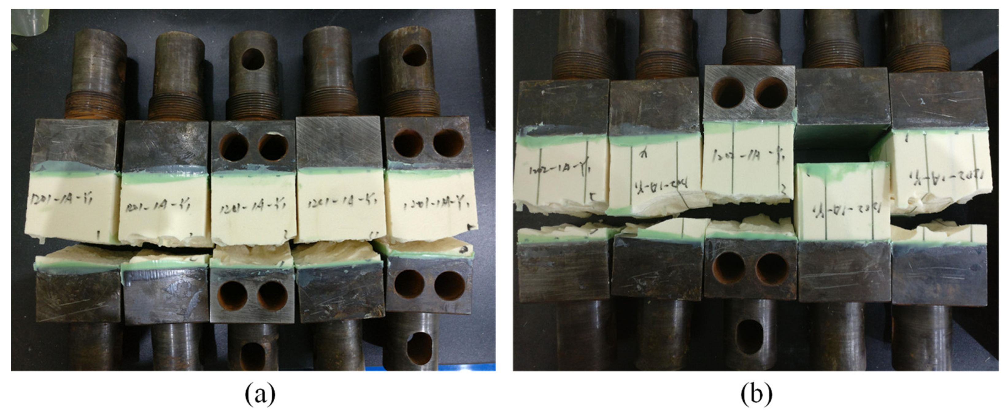
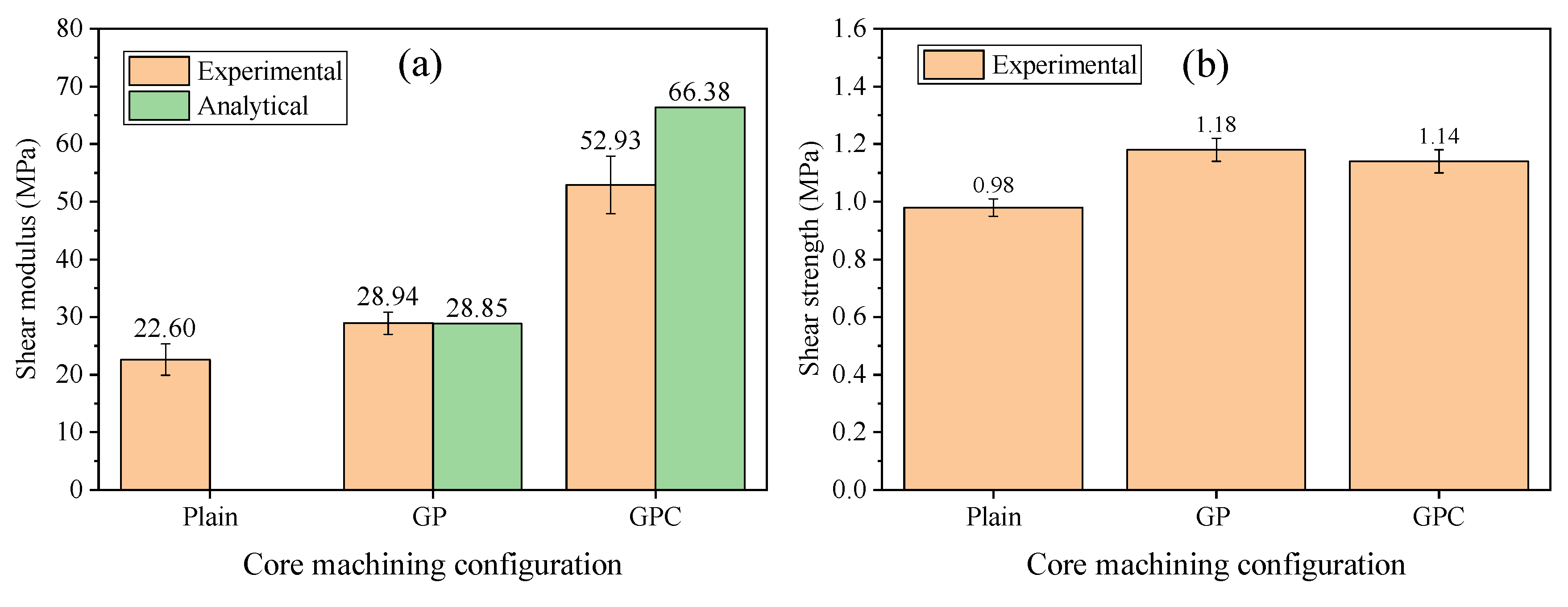
3.3. Shear Test
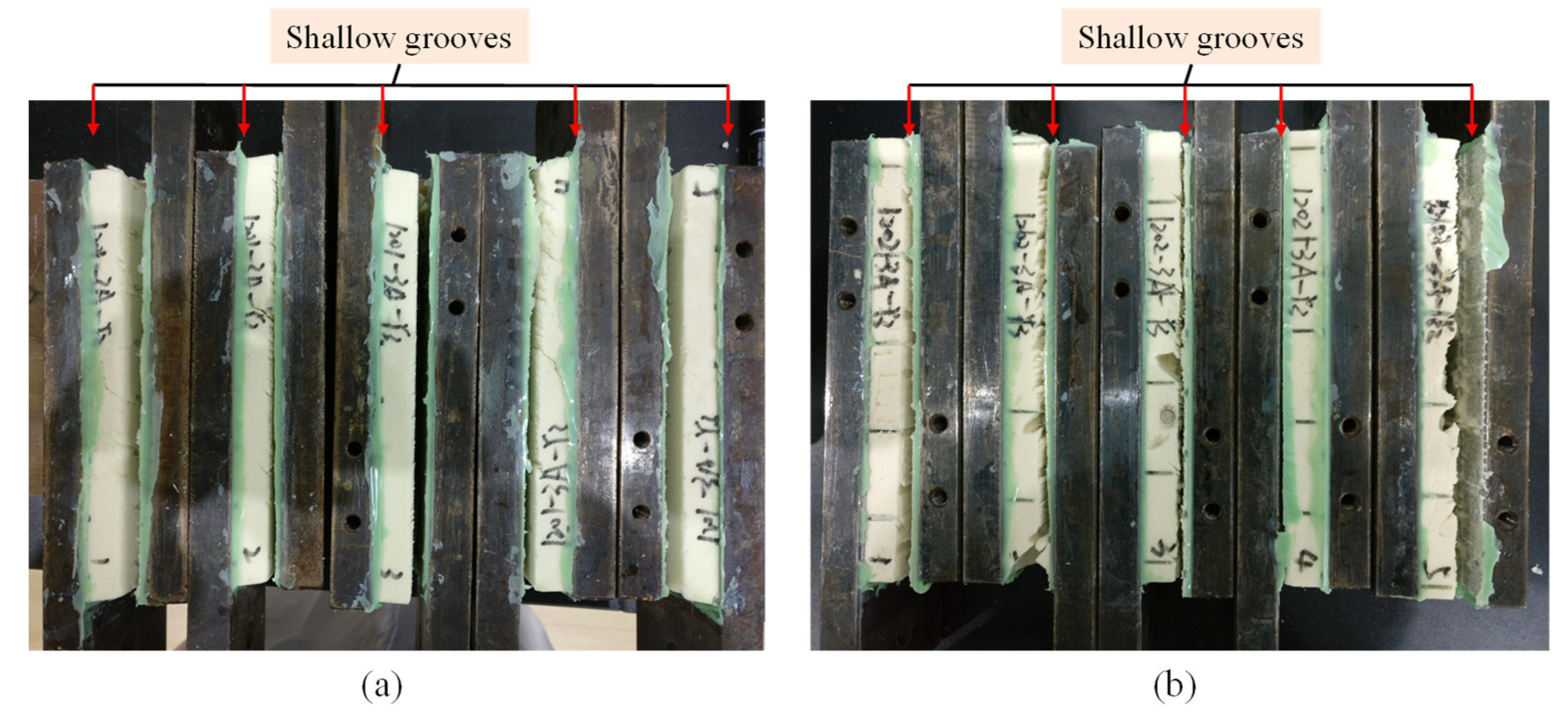
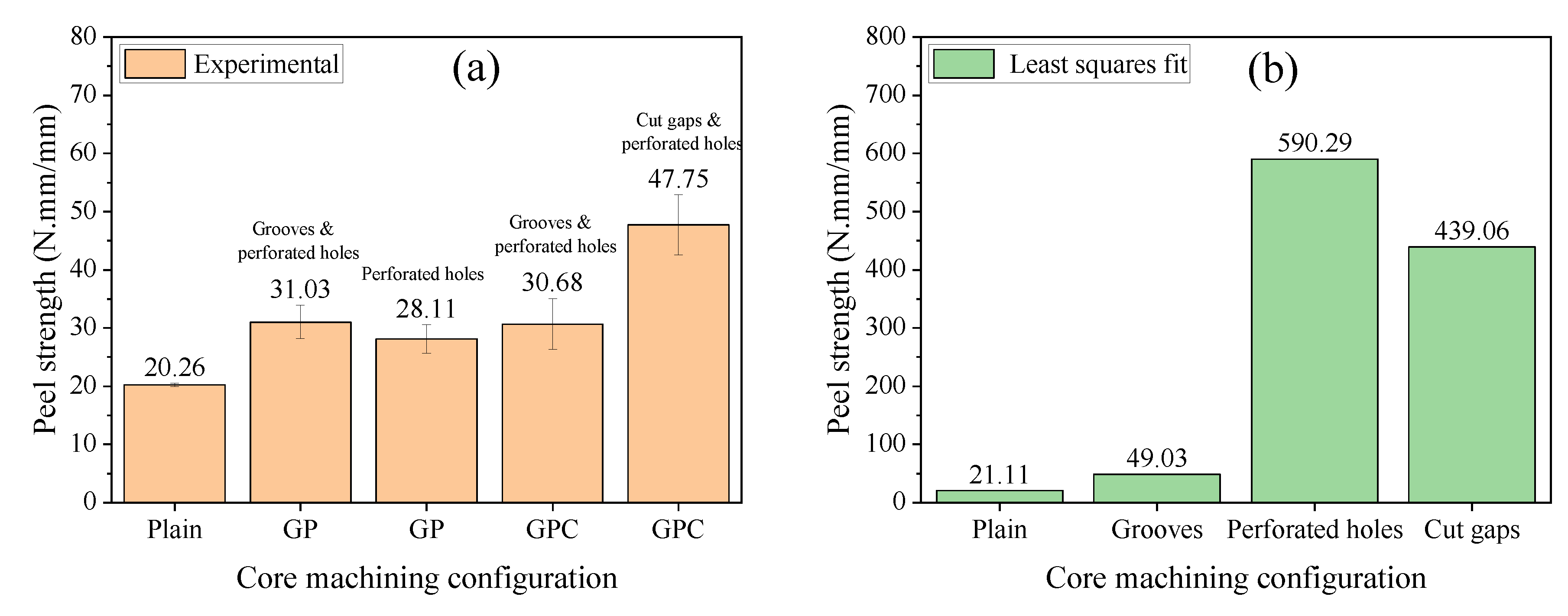
3.4. Peel Test
3.5. Cost Evaluation
4. Conclusions
- (1)
- The GP and GPC machining configurations can greatly improve the tensile, compressive, and shear moduli, and compressive strength of the cores in the condition of a small volume fraction of infused resin. Analytical models can predict these mechanical properties with desired accuracy, but fail to estimate the tensile strength due to stress concentration.
- (2)
- The tensile strength of the infused GP and GPC cores was barely improved compared with the pure foam core. This was due to the stress concentration of abrupt resin cross-section shaped by the irregular foam cell and the shear-lag phenomenon of the resin column/foam interface.
- (3)
- The shear strength of the infused GP and GPC cores increased in a small amount compared with the pure foam core, which was determined by local structure around the face sheet/core interface. The comparative strength of the resin, the foam, and the fiber/matrix interface determined the fracture surface and the final shear strength.
- (4)
- Thick resin columns filled in the perforated holes and contour cuts had relatively large face sheet/core peel capacity, and thin resin channels filled in the grooves had limited improvement on the peel capacity.
- (5)
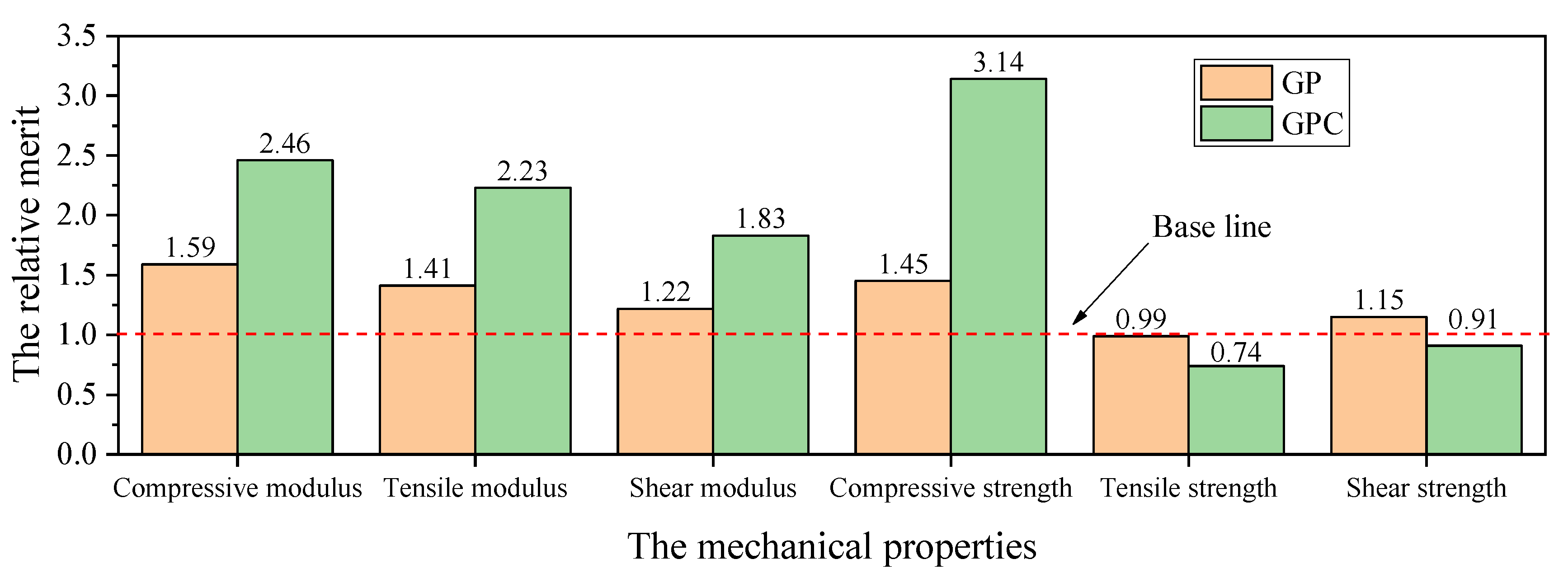
- Both GP and GPC cores gained positive effects on the compressive, tensile, and shear moduli, and compressive strength in consideration of the core cost after resin infusion, but the GPC core exhibited a negative effect in tensile strength.
Author Contributions
Funding
Institutional Review Board Statement
Informed Consent Statement
Data Availability Statement
Acknowledgments
Conflicts of Interest
Abbreviations
| PVC | Polyvinyl chloride |
| PET | Polyethylene terephthalate |
| PU | Polyurethane |
| GP | Grooved and perforated hole machining |
| GPC | Grooved, perforated hole and contour cut machining |
| Nomenclature | |
| Symbol | Designation |
| The relative merit of infused core, compared with the plain core | |
| The mechanical property of the infused core | |
| The mechanical property of the plain core | |
| The unit cost of the infused core | |
| The unit cost of the plain core | |
| Groove spacing for GP | |
| Groove spacing for GPC | |
| Groove height for GP | |
| Groove height for GPC | |
| Groove width for GP | |
| Groove width for GPC | |
| Perforated hole spacing for GP | |
| Perforated hole spacing for GPC | |
| Perforated hole diameter for GP | |
| Perforated hole diameter for GPC | |
| Contour cut spacing for GPC | |
| Contour cut width GPC | |
| Equivalent thickness of resin layer filled in the foam surfaces | |
| The compressive modulus of plain core | |
| The compressive modulus of resin | |
| The tensile modulus of plain core | |
| The tensile modulus of resin | |
| The compressive modulus of infused GP core | |
| The tensile modulus of infused GP core | |
| The shear modulus of plain core | |
| The shear modulus of resin | |
| The shear modulus of infused GP core | |
| The volume fraction of infused resin in infused GP core | |
| The volume fraction of foam in infused GP core | |
| The coefficients in semi-experimental Halpin-Tsai theory | |
| The coefficients in semi-experimental Halpin-Tsai theory | |
| The compressive modulus of infused GPC core | |
| The tensile modulus of infused GPC core | |
| The volume fraction of cutting in infused GPC core | |
| The volume fraction of perforated hole in infused GPC core | |
| The volume fraction of cutting and perforated hole in infused GPC core | |
| The shear modulus of infused GPC core | |
| Resin ratio, assigned in Nickel’s formula | |
| Resin ratio, assigned in Nickel’s formula | |
| The equivalent shear modulus of infused GP core | |
| The compressive strength of infused GP core | |
| The tensile strength of infused GP core | |
| The compressive strength of infused GPC core | |
| The tensile strength of infused GPC core | |
| The compressive stress of the foam at the strain that the GP core arrived at the peak load based on the linear mixture of the stress-strain curves of resin and foam | |
| The compressive stress of the resin at the strain that the GP core arrived at the peak load based on the linear mixture of the stress-strain curves of resin and foam | |
| The tensile stress of the foam at the strain that the GP core arrived at the peak load based on the linear mixture of the stress-strain curves of resin and foam | |
| The tensile stress of the resin at the strain that the GP core arrived at the peak load based on the linear mixture of the stress-strain curves of resin and foam | |
| The compressive stress of the foam at the strain that the GPC core arrived at the peak load based on the linear mixture of the stress-strain curves of resin and foam | |
| The compressive stress of the resin at the strain that the GPC core arrived at the peak load based on the linear mixture of the stress-strain curves of resin and foam | |
| The tensile stress of the foam at the strain that the GPC core arrived at the peak load based on the linear mixture of the stress-strain curves of resin and foam | |
| The tensile stress of the resin at the strain that the GPC core arrived at the peak load based on the linear mixture of the stress-strain curves of resin and foam |
Appendix A
References
- Mouritz, A. Review of z-pinned laminates and sandwich composites. Compos. Part A Appl. Sci. Manuf. 2020, 139, 106128. [Google Scholar] [CrossRef]
- Marasco, A.I.; Cartié, D.D.; Partridge, I.K.; Rezai, A. Mechanical properties balance in novel Z-pinned sandwich panels: Out-of-plane properties. Compos. Part A Appl. Sci. Manuf. 2006, 37, 295–302. [Google Scholar] [CrossRef] [Green Version]
- Du, L.; Guiqiong, J.; Tao, H. The elastic properties of sandwich structure with Z-pinned foam core. J. Reinf. Plast. Compos. 2009, 28, 813–831. [Google Scholar] [CrossRef]
- Nanayakkara, A.; Feih, S.; Mouritz, A. Experimental analysis of the through-thickness compression properties of z-pinned sandwich composites. Compos. Part A Appl. Sci. Manuf. 2011, 42, 1673–1680. [Google Scholar] [CrossRef]
- Abdi, B.; Azwan, S.; Abdullah, M.; Ayob, A.; Yahya, Y.; Xin, L. Flatwise compression and flexural behavior of foam core and polymer pin-reinforced foam core composite sandwich panels. Int. J. Mech. Sci. 2014, 88, 138–144. [Google Scholar] [CrossRef]
- Zhou, J.; Guan, Z.; Cantwell, W.; Liao, Y. The energy-absorbing behaviour of foam cores reinforced with composite rods. Compos. Struct. 2014, 116, 346–356. [Google Scholar] [CrossRef]
- Kim, J.H.; Lee, Y.S.; Park, B.J.; Kim, D.H. Evaluation of durability and strength of stitched foam-cored sandwich structures. Compos. Struct. 1999, 47, 543–550. [Google Scholar] [CrossRef]
- Potluri, P.A.; Kusak, E.; Reddy, T. Novel stitch-bonded sandwich composite structures. Compos. Struct. 2003, 59, 251–259. [Google Scholar] [CrossRef]
- Lascoup, B.; Aboura, Z.; Khellil, K.; Benzeggagh, M. On the mechanical effect of stitch addition in sandwich panel. Compos. Sci. Technol. 2006, 66, 1385–1398. [Google Scholar] [CrossRef]
- Lascoup, B.; Aboura, Z.; Khellil, K.; Benzeggagh, M. Impact response of three-dimensional stitched sandwich composite. Compos. Struct. 2010, 92, 347–353. [Google Scholar] [CrossRef]
- Han, F.; Yan, Y.; Ma, J. Experimental study and progressive failure analysis of stitched foam-core sandwich composites subjected to low-velocity impact. Polym. Compos. 2018, 39, 624–635. [Google Scholar] [CrossRef]
- Shigang, A.; Yiqi, M.; Yongmao, P.; Daining, F.; Liqun, T. Effect of stitching angle on mechanical properties of stitched sandwich panels. Mater. Des. 2013, 50, 817–824. [Google Scholar] [CrossRef]
- Hu, Y.; Zhu, J.; Wang, J.; Wu, Y. Interfacial Failure in Stitched Foam Sandwich Composites. Materials 2021, 14, 2275. [Google Scholar] [CrossRef]
- Rosemeier, M.; Buriticá, P.; Antoniou, A. Impact of resin uptake of core materials on buckling of wind turbine blades. J. Phys. Conf. Ser. 2018, 1037, 1–12. [Google Scholar] [CrossRef]
- Stoll, F.C. Optimal Design of Sandwich Core for Wind Turbine Blade Buckling Resistance. In Proceedings of the 32nd ASME Wind Energy Symposium, National Harbor, MD, USA, 13–17 January 2014; pp. 1–21. [Google Scholar]
- Truxel, A.; Aviles, F.; Carlsson, L.A.; Grenestedt, J.L.; Millay, K. Influence of face/core interface on debond toughness of foam and balsa cored sandwich. J. Sandw. Struct. Mater. 2006, 8, 237–258. [Google Scholar] [CrossRef]
- Massüger, L.; Gätzi, R. Effects of groove configurations on fatigue resistance of infused sandwich panels. In Proceedings of the 10th International Conference on Flow Processes in Composite Materials, Monte Verità, Switzerland, 11–15 July 2010. [Google Scholar]
- Berger, L.; Loiselet, K.; Dransfeld, C. Filling or Not Filling the Slits in Contourable Sandwich Cores with Resin?—Effect on the Properties of the Sandwich Construction. In Proceedings of the 25th SAMPE Europe Conference, Paris, France, 30 March–1 April 2004. [Google Scholar]
- May-Pat, A.; Aviles, F.; Aguilar, J.O. Mechanical properties of sandwich panels with perforated foam cores. J. Sandw. Struct. Mater. 2011, 13, 427–444. [Google Scholar] [CrossRef]
- Mitra, N.; Raja, B.R. Improving delamination resistance capacity of sandwich composite columns with initial face/core debond. Compos. Part B Eng. 2012, 43, 1604–1612. [Google Scholar] [CrossRef]
- Halimi, F.; Golzar, M.; Asadi, P.; Beheshty, M.H. Core modifications of sandwich panels fabricated by vacuum-assisted resin transfer molding. J. Compos. Mater. 2013, 47, 1853–1863. [Google Scholar] [CrossRef]
- Fathi, A.; Wolff-Fabris, F.; Altstaedt, V.; Gaetzi, R. An investigation on the flexural properties of balsa and polymer foam core sandwich structures: Influence of core type and contour finishing options. J. Sandw. Struct. Mater. 2013, 15, 487–508. [Google Scholar] [CrossRef]
- Yokozeki, T.; Iwamoto, K. Effects of core machining configuration on the debonding toughness of foam core sandwich panels. Adv. Compos. Mater. 2016, 25, 45–58. [Google Scholar] [CrossRef]
- Yalkin, H.E.; Icten, B.M.; Alpyildiz, T. Enhanced mechanical performance of foam core sandwich composites with through the thickness reinforced core. Compos. Part B Eng. 2015, 79, 383–391. [Google Scholar] [CrossRef]
- Yalkin, H.E.; Icten, B.M.; Alpyildiz, T. Tensile and compressive performances of foam core sandwich composites with various core modifications. J. Sandw. Struct. Mater. 2017, 19, 49–65. [Google Scholar] [CrossRef]
- Balıkoğlu, F.; Arslan, N.; Demircioğlu, T.; İnal, O.; Iren, M.; Ataş, A. Improving four-point bending performance of marine composite sandwich beams by core modification. J. Compos. Mater. 2020, 54, 1049–1066. [Google Scholar] [CrossRef]
- ASTM C297/C297M-16; Standard Test Method for Flatwise Tensile Strength of Sandwich Constructions. ASTM International: West Conshohocken, PA, USA, 2010; pp. 1–8.
- ASTM C365/C365M-16; Standard Test Methods for Flatwise Compressive Properties of Sandwich Cores. ASTM International: West Conshohocken, PA, USA, 2016; pp. 1–8.
- Hörrmann, S.; Adumitroaie, A.; Viechtbauer, C.; Schagerl, M. The effect of fiber waviness on the fatigue life of CFRP materials. Int. J. Fatigue 2016, 90, 139–147. [Google Scholar] [CrossRef]
- ASTM D1787-98; Standard Test Method for Climbing Drum Peel for Adhesives. ASTM International: West Conshohocken, PA, USA, 2012; (Reapproved 2012). pp. 1–4.
- Jones, R.M. Mechanics of Composite Materials, 2nd ed.; Taylor & Francis Group: New York, NY, USA, 1999. [Google Scholar]
- Beer, F.P.; Johnston, E.R.; Dewolf, J.T.; Mazurek, D.F. Mechanics of Materials, 5th ed.; McGraw-Hill Higher Education: New York, NY, USA, 2009. [Google Scholar]
- Pilkey, W.D.; Pilkey, D.F.; Bi, Z. Peterson’s Stress Concentration Factors; John Wiley & Sons: Hoboken, NJ, USA, 2020. [Google Scholar]
- You, Y.-J.; Kim, J.-H.J.; Park, K.-T.; Seo, D.-W.; Lee, T.-H. Modification of rule of mixtures for tensile strength estimation of circular GFRP rebars. Polymers 2017, 9, 682. [Google Scholar] [CrossRef] [PubMed] [Green Version]
- Rebhi, L.; Dinulović, M.; Dunjić, M.; Grbović, A.; Krstić, B. Calculation of the effective shear modulus of composite sandwich panels. FME Trans. 2017, 45, 537–542. [Google Scholar] [CrossRef]
- Nickel, A. Optimierung der Designparameter von GFK-Kern-Verbunden unter Ber¨ ucksichtigung der Harzaufnahme des Kerns (Technische Universit¨ at Berlin); Institut für Luft- und Raumfahrt Fachgebiet Luftfahrzeugbau und Leichtbau: Berlin, Germany, 2011; pp. 1–97. [Google Scholar]
- ASTM D5573-99; Standard Practice for Classifying Failure Modes in Fiber-Reinforced-Plastic (FRP) Joints. ASTM International: West Conshohocken, PA, USA, 2012; (Reapproved 2012). pp. 1–3.
- Totten, K.R.; Kutub, B.; Carlsson, L.A. In situ determination of the fiber–matrix interface tensile strength. J. Compos. Mater. 2016, 50, 589–599. [Google Scholar] [CrossRef]


| Nomenclature | |||||||
| Value/mm | 20 × 20 | 2.0 | 2.0 | 20 × 20 | 2.0 | 0.170 | |
| Nomenclature | |||||||
| Value/mm | 20 × 20 | 2.0 | 2.0 | 30 × 30 | 2.0 | 30 × 30 | 0.531 |
| Test Types | Dimensions (Length × Width × Height) |
|---|---|
| Tensile test | 60 mm × 60 mm × 50 mm |
| Compressive test | 60 mm × 60 mm × 50 mm |
| Shear test | 150 mm × 60 mm × 12.5 mm |
| Peel test | 240 + (2 × 30) mm × 60 mm × 25 mm |
Publisher’s Note: MDPI stays neutral with regard to jurisdictional claims in published maps and institutional affiliations. |
© 2022 by the authors. Licensee MDPI, Basel, Switzerland. This article is an open access article distributed under the terms and conditions of the Creative Commons Attribution (CC BY) license (https://creativecommons.org/licenses/by/4.0/).
Share and Cite
Qin, Z.; Wei, L.; Zhang, M.; Zhang, R.; Ji, X.; Song, X.; Qiang, S. The Effects of Core Machining Configurations on the Mechanical Properties of Cores and Sandwich Structures. Materials 2022, 15, 521. https://doi.org/10.3390/ma15020521
Qin Z, Wei L, Zhang M, Zhang R, Ji X, Song X, Qiang S. The Effects of Core Machining Configurations on the Mechanical Properties of Cores and Sandwich Structures. Materials. 2022; 15(2):521. https://doi.org/10.3390/ma15020521
Chicago/Turabian StyleQin, Zhiwen, Lili Wei, Mingming Zhang, Rui Zhang, Xiang Ji, Xiaofei Song, and Shengguan Qiang. 2022. "The Effects of Core Machining Configurations on the Mechanical Properties of Cores and Sandwich Structures" Materials 15, no. 2: 521. https://doi.org/10.3390/ma15020521
APA StyleQin, Z., Wei, L., Zhang, M., Zhang, R., Ji, X., Song, X., & Qiang, S. (2022). The Effects of Core Machining Configurations on the Mechanical Properties of Cores and Sandwich Structures. Materials, 15(2), 521. https://doi.org/10.3390/ma15020521