1. Introduction
Zirconia-based solid oxide electrolyte is one of the most widely used solid electrolytes for solid oxide electrochemical cells (SOEC). It is typically doped with a trivalent cation such as yttrium to create oxygen vacancies and to stabilize the cubic structure. Yttria-stabilized zirconia (YSZ) is the typical zirconia-based solid electrolyte used for SOECs due to its high oxide ion conductivity at elevated temperatures [
1,
2,
3,
4]. Scandia-stabilized zirconia (ScSZ), on the other hand, is also used as a solid electrolyte due to its remarkable higher ionic conductivity, almost 3x, as compared to YSZ; however, the high conductivity of the cubic phase ScSZ is limited to a narrow temperature range and with the cubic phase structural stability dependent on doping concentration and temperature [
5,
6,
7,
8]. In order to circumvent these concerns and to improve the solid electrolyte properties and performance, fabrication into thin films and co-doping are some of the promising solutions.
Co-doping of scandium and yttrium into zirconia (ScYSZ) has been reported in the literature [
8,
9,
10,
11,
12,
13]. The incorporation of Y
3+ and Sc
3+ as co-dopants into ZrO
2 structure can either stabilize the cubic/tetragonal phase to achieve a better or desired property such as higher conductivity as compared to single doping [
8,
9,
10,
11] and can provide good mechanical and thermal stability desirable for certain applications [
14]. On the other hand, the fabrication of solid electrolytes into thin films may further increase the conductivity and is crucial for the development of a micron-sized SOEC system (μ-SOEC). ScYSZ thin film showed higher ionic conductivity (1.2 × 10
−1) at 700 °C (0.7 eV activation energy) as compared to bulk solid electrolytes [
8,
13,
15].
Vapor phase deposition methods are very useful in developing thin films such as nanometer-scale electrode-electrolyte systems. Among these methods, pulsed laser deposition (PLD) has been used for the fabrication of electrolyte thin films with lower ohmic resistance and high-quality films with good morphological features. Such thin films can be attained by simply tuning the stoichiometry of the PLD target material and different deposition parameters [
16,
17]. Most papers have focused on the fabrication of YSZ [
18,
19,
20,
21,
22,
23,
24,
25] and ScSZ [
6] via PLD and very limited reports on PLD deposited co-doped ScYSZ thin films.
The crystal structure, phase stability, and morphology are important factors that affect the properties such as the conductivity of solid electrolytes and other properties desirable for specific applications. Cubic YSZ has high ionic conductivity; however, its polymorph, tetragonal phase, although has lower conductivity, shows interesting high mechanical strength and hardness particularly also useful for solid oxide electrochemical cells applications [
14,
26,
27,
28]. For ScSZ, the reported ionic conductivity trend, high to low, is cubic > tetragonal > rhombohedral > monoclinic (with tetragonal phase), respectively [
29]. In addition, ScSZ denser films were prepared also at low oxygen partial pressure using low-pressure plasma spray to achieve higher oxygen ion transport performance [
30]. In the fabrication of thin films using PLD, the resulting crystal structure and morphology of the deposited thin films, which directly affect the electrical properties of the thin films, are dependent on the parameters employed during deposition [
24,
25]. For YSZ, deposited thin films show the evolution of microstructure from porous to dense thin films. High deposition temperature and lower oxygen partial pressure resulted in dense microstructure and less dense at increasing oxygen partial pressure. Dense microstructure thin film has high oxygen ion conductivity while porous thin films have low oxygen ion conductivity but have high protonic conductivity [
25,
31,
32]. For scandium and yttrium co-doped zirconia or ScYSZ thin films, very limited information or none so far has been reported on the effects of PLD deposition parameters on the properties of ScYSZ solid electrolyte thin films. Hence, it is important to explore and investigate ScYSZ thin films fabricated via PLD.
In this study, in order to tailor and to provide an understanding of the quality of Sc and Y co-doped ZrO2 thin films produced via PLD, the effects of different PLD deposition parameters such as oxygen partial pressure and substrate temperature on the crystal structure and morphology of Sc-Y co-doped ZrO2 deposited thin films were investigated. The properties of prepared thin films were analyzed using X-ray diffraction (XRD), Raman spectroscopy, scanning electron microscopy (SEM), and Photoemission spectroscopy (PES).
2. Materials and Methods
The PLD ScYSZ target material, scandium and yttrium co-doped zirconia having a chemical composition of Zr0.4Y0.8Sc0.8O1.92, was prepared via solid state reaction method using ZrO2 (5–25 nm, 97.2%, EM Futur, Castellon, Spain), Sc2O3 (99.9% Sigma-Aldrich, Inc., St. Louis, MO, USA), and Y2O3 (<50 nm, Sigma-Aldrich, Inc., St. Louis, MO, USA) powders. The as-calcined powder was pelletized using uniaxial pressing and finally sintered at 1400 °C in ambient condition and was used as target material for PLD. ScYSZ thin films were ablated, with a 30 mm distance, on Si with native SiO2 oxide substrate using Nd3+: YAG laser (LOTIS TII (LS-2137U), λ = 266 nm), Tokyo Instruments, Inc., Tokyo, Japan using laser energy of 38 J and a repetition rate of 10 Hz. The pulse duration was 10 ns, the area of the beam was 9.8 × 10−³ cm2 and a plano-convex lens was used with a focal length of 400 mm. The as-deposited ScYSZ thin films were prepared and investigated using various PLD substrate temperatures (Ts = 25 °C, 200 °C, 400 °C, 600 °C, 800 °C) and oxygen partial pressures ( = 0.01 Pa, 0.1 Pa, 1.0 Pa, and 10 Pa).
The crystal structure of the as-deposited ScYSZ thin films was determined using Rigaku SmartLab X-ray Diffractometer (Rigaku Corporation, Tokyo, Japan). XRD analysis was performed using a 2-theta measurement (through NIMS-Namiki Foundry Facility, Tsukuba, Japan), equivalent to the grazing technique used for thin-film characterization. Scanning was obtained with CuKα (λ = 1.54 nm), resolution of 0.01, and 2θ scan range from 20° to 80° with 5°/min scan rate. To further investigate the crystal structure and polymorphs of ScYSZ thin films, JASCO NRS-5100 Laser Raman spectrometer (Jasco International Co., Ltd., Tokyo, Japan) was used. Raman shift of the as-deposited thin films was obtained with the wavenumber ranges from 100 cm−1 to 1200 cm−1 at room temperature. Field Emission-Scanning Electron Microscopy (FE-SEM) S-4800 (Hitachi High-Tech., Corp., Tokyo, Japan) was used to observe the morphological features of as-deposited ScYSZ thin films. Before the sample measurements, Pt films were sputtered on the surface of ScYSZ film for 20 s. Both the surface structure and the cross-sectional images were captured. Photoemission Spectroscopy (PES) was performed with Beamline 3.2Ua Photoelectron spectroscopy at the Synchrotron Light Research Institute, Nakhon Ratchasima, Thailand. The electron energy was analyzed by CLAM2 (Thermo VG Scientific, England, UK). The photon energy was 600 eV and the total energy resolution was about 2 eV. The base pressure was 2 × 10⁻⁸ Pa.
3. Results and Discussions
3.1. X-ray Diffraction Analysis
Figure 1 shows the diffraction peaks of polycrystalline as-deposited ScYSZ thin films using different deposition parameters:
Ts and
.
Figure 1a shows that at increasing deposition temperature, crystallized ScYSZ thin films were obtained. The as-deposited ScYSZ thin films at about 25 °C or room temperature (RT) is amorphous and crystallization started at 200 °C, then well-crystallized peaks can be observed from 600 °C to 800 °C. The diffraction peaks at
2θ ≈ 30° (111), 35° (200), 50° (220), 60° (311), 63° (222), and 75° (400) can be indexed and attributed to cubic ZrO
2-phase (ICSD No. 00-078-1808). This result is similar to the diffraction peaks measured for the target pellet and is observed to agree with the previous studies in [
17,
24,
25] on YSZ thin films on SiO
2-Si substrate. On the other hand, the effect of oxygen partial pressure on the crystal structure of ScYSZ thin films is shown in
Figure 1b. As shown in the XRD stacked patterns, similar peaks can be observed for the different oxygen partial pressures; however, more crystalline or high-intensity peaks are observable for the oxygen-deficient environment or lower oxygen partial pressure,
= 0.01 Pa and 0.1 Pa, as compared to higher oxygen partial pressures peak intensities.
3.2. Raman Spectroscopy
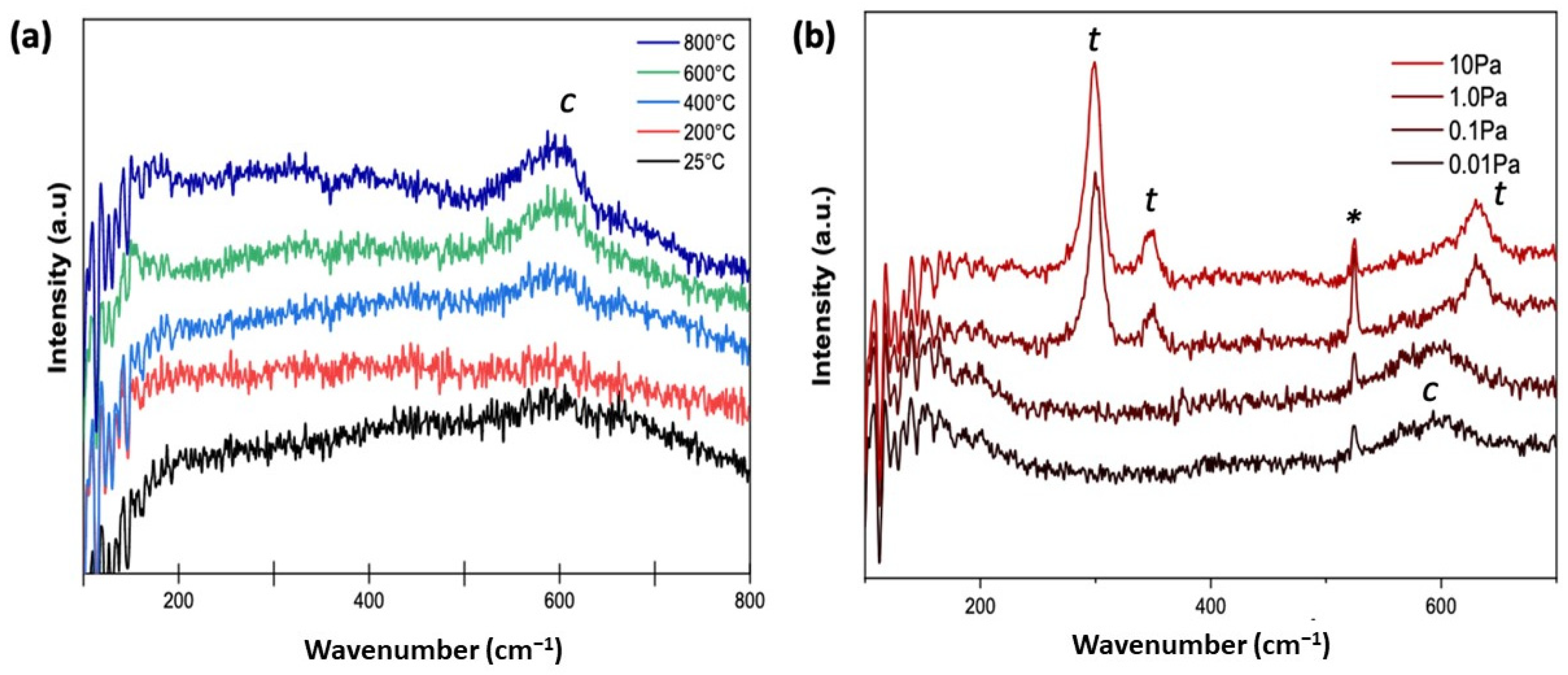
Figure 2a depicts the Raman spectra of the as-deposited ScYSZ thin films. When deposited at increasing deposition temperature, ScYSZ thin films show mostly cubic (
c) phase with distinct Raman shift at approx. 600 cm
−1. On the other hand, while the XRD results revealed only cubic phases for all deposited samples, due to sensitivity of Raman spectroscopy to local structure and disordering as compared to XRD, there is an observed transition from cubic phase to tetragonal (
t) phase for ScYSZ thin films deposited with increasing oxygen partial pressure as shown in
Figure 2b.
As revealed in
Figure 2b, in an oxygen-deficient environment or low oxygen partial pressures,
= 0.01 Pa and
= 0.1 Pa, only a single Raman band at around 600 cm
−1 was observed suggesting a cubic ZrO
2 fluorite structure [
28,
33]. However, at increasing oxygen partial pressure, from
= 1.0 Pa to
= 10 Pa, Raman bands at approx. 298 cm
−1, 350 cm
−1, 630 cm
−1 are observable which can be attributed to coupling of Zr-O′ stretching, O(O′)-Zr-O(O′) bending, and Zr-O stretching vibrational modes, respectively [
10,
28,
34]. The observed Raman band at around 524 cm
−1 is attributed to vibrational mode coming from the SiO
2 substrate which is more distinct at high oxygen partial pressures.
3.3. Microstructural Properties
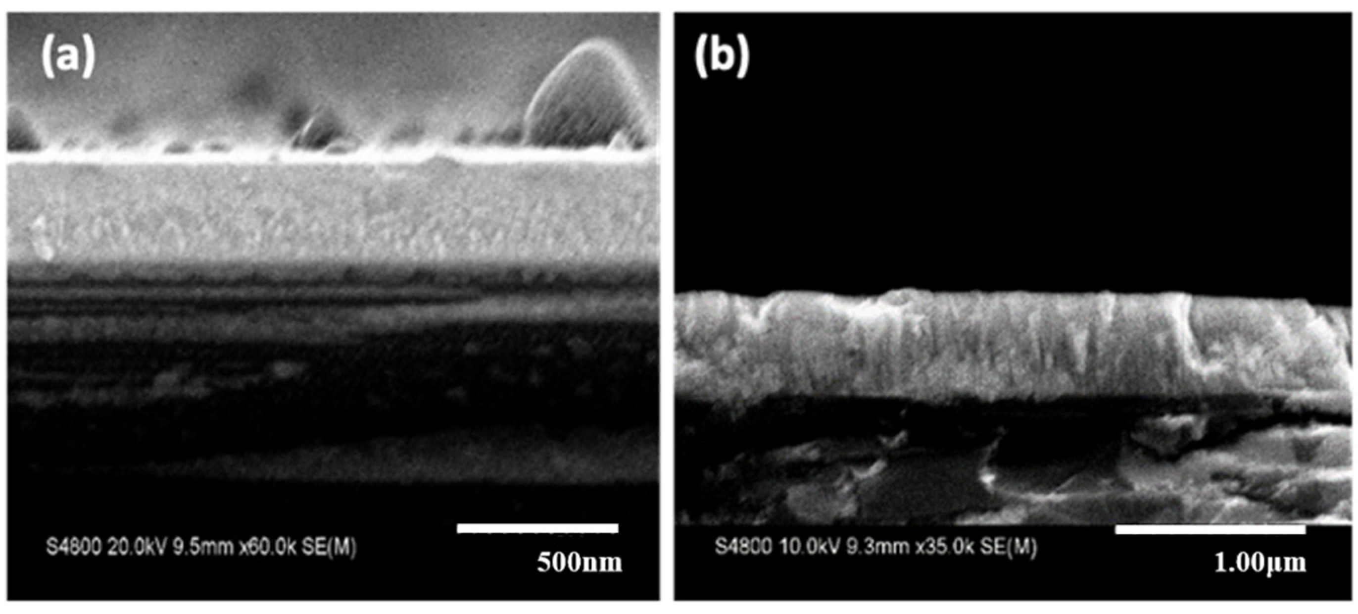
Figure 3 shows the cross-sectional SEM images of the deposited thin films for
Ts = 25 °C (
Figure 3a) and
Ts = 800 °C (
Figure 3b) with oxygen partial pressure of
= 0.1 Pa and deposition rate of about 70 nm/h. Although both substrate temperatures showed a dense morphology, a more crystalized columnar structure can be observed at high substrate temperature.
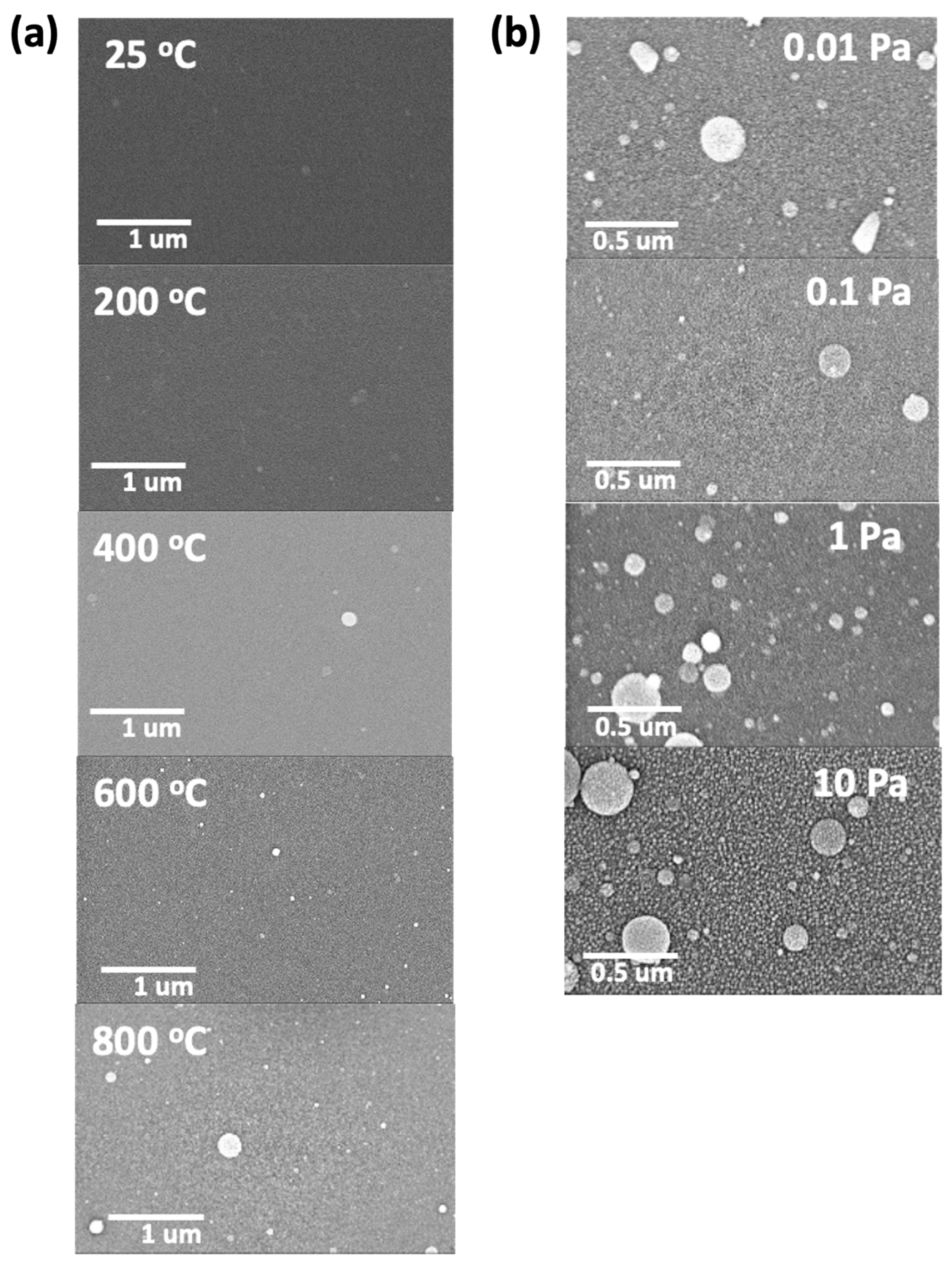
The surface morphologies of the deposited thin films at different substrate temperatures and oxygen partial pressures are shown in
Figure 4a,b, respectively. As can be observed in
Figure 4a, the images revealed dense and crack-free surfaces, with the presence of droplets or circular agglomerates that increases at increasing deposition temperature. These agglomerated droplets are ScYSZ particles which are characteristic deposits for oxide films prepared using Nd:YAG laser system in PLD [
20,
33,
35]. On the other hand,
Figure 4b showed the SEM surface images of the as-deposited thin film on SiO
2-Si substrate at various oxygen partial pressure. At increasing oxygen partial pressure, more porous and rough surface microstructures are observable. This effect on the surface morphology using higher oxygen partial pressure during deposition is consistent with reported works on the microstructure of ZrO
2 thin films [
19,
24,
25,
36].
3.4. Photoemission Spectroscopy (PES)
The co-doping of Sc and Y in ZrO
2 and its effect on the resulting thin film structure was verified by the presence of the element’s core levels and with binding energies using PES analysis [
37,
38,
39] and the results are shown in
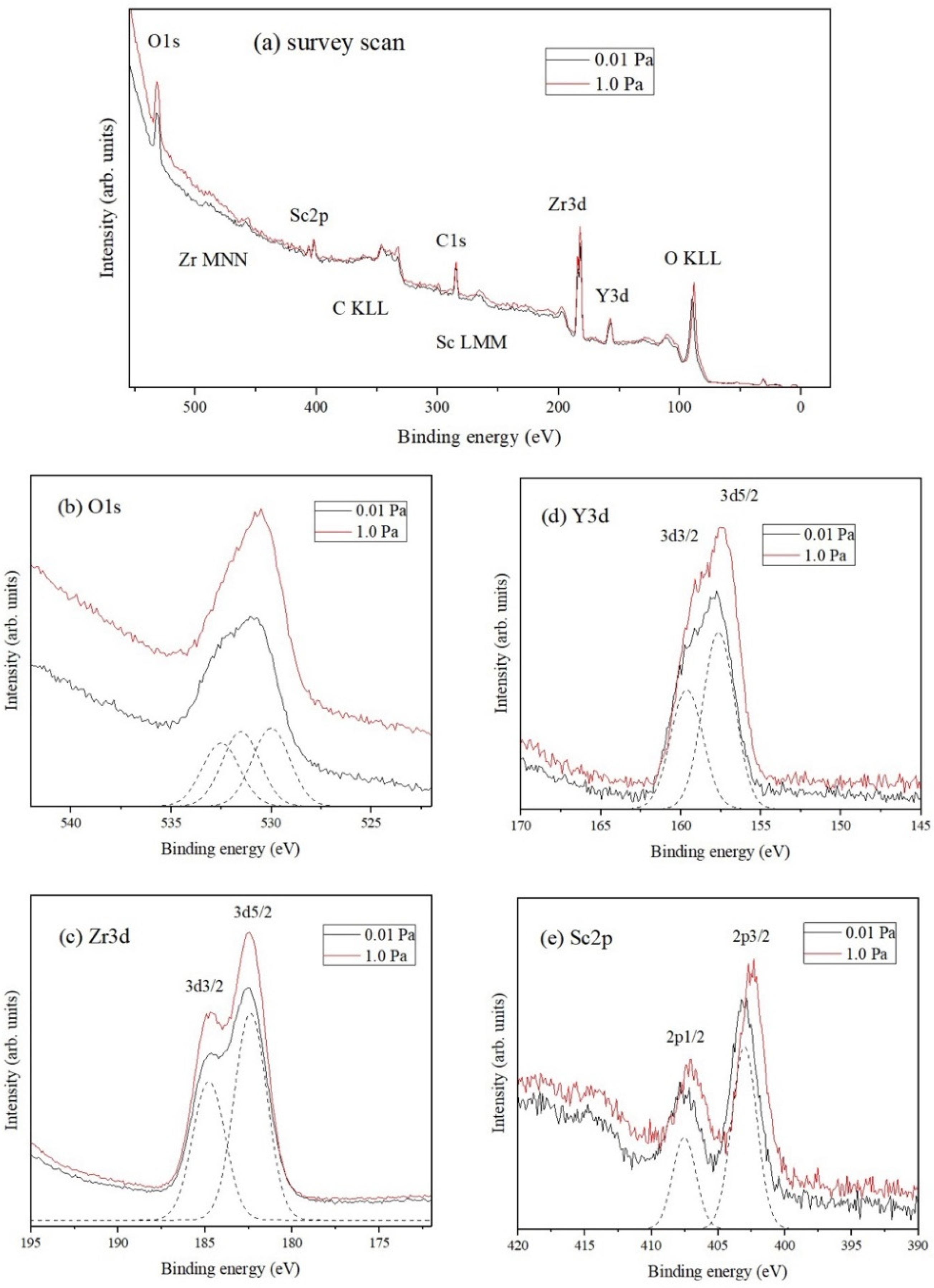
Figure 5.
Figure 5a shows the wide scan spectra for ScYSZ thin films deposited with
= 0.01 Pa and
1.0 Pa with binding energies and peaks identified for O 1s, Sc 2p, Zr 3p and Zr 3d, Y 3p and Y 3d, and O
KLL core levels. The binding energy of the spectra was referenced from C 1s at 284.6 eV. PES peaks position for Zr 3d is at 181 eV to 183 eV which corresponds to the Zr
4+ valence state. On the other hand, for Y 3d, the peak position is at around 158 eV for Y
3+ valence state [
40,
41] and the peaks for Sc 2p are at around 402 eV to 403 eV for the Sc
3+ valence states [
38,
42]. For the O 1s core levels, the peaks are expected at binding energies around 530 eV to 532 eV for lattice oxygen and hydroxyl [
39], respectively, and O KLL is expected at 92 eV. The narrow scans for different core levels are shown in
Figure 5b–e.
Figure 5b shows the PES stacked spectra of the O 1s core level for ScYSZ thin films deposited at
= 0.01 Pa and
1.0 Pa. The PES spectrum was observed to be slightly asymmetric for both
, 0.01 Pa and 1.0 Pa. A sample deconvolution of the peaks, for the 0.01 Pa spectrum, is also shown. As revealed, O 1s can be deconvoluted or fitted into three peaks centered at 530.0, 531.5, and 532.5 eV, for both
. These binding energies are typical values for O1s lattice oxygen (oxygen bonded with Zr and/or Sc/Y), hydroxyl, and weakly adsorbed oxygen/H
2O [
42,
43,
44,
45]. The PES stacked spectra of Zr 3d, Y 3d, and Sc 2p for the two oxygen partial pressures are shown in
Figure 5c–e, respectively. Spin-orbit splitting can be observed from these spectra.
Figure 5c shows the PES spectra of Zr 3d consisting of Zr 3d
5/2 and Zr 3d
3/2, corresponding to the Zr
4+ valence state, with binding energies located at 182.4 eV and 184.8 eV for
1.0 Pa, respectively. On the other hand,
Figure 5d shows the PES spectrum of Y 3d that is slightly asymmetric which consists of Y 3d
5/2 and Y 3d
3/2 with binding energies located 157.2 eV and 159.2 eV for
1.0 Pa corresponding to the Y
3+ valence state. The PES spectrum of Sc 2p consisting of Sc 2p
3/2 and Sc 2p
1/2 is shown in
Figure 5e, with binding energies located at 402.4 eV and 406.9 eV (
1.0 Pa), corresponding to Sc
3+ valence state.
The effects of increasing
in the ScYSZ thin film deposition are observable by the slight shifting in the binding energies of the dopants (Y 3d/Sc 2p) core levels. The Y 3d peak shifts from 157.6 eV to 157.2 eV while Sc 2p3/2 peak shifts from 403.0 eV to 402.4 eV as oxygen pressure increases from
= 0.01 Pa to
= 1.0 Pa. This means that ScYSZ thin films deposited at
= 0.01 Pa suggested a higher concentration of oxygen vacancy as compared with ScYSZ thin films deposited at
= 1.0 Pa [
39]. It can be said that the lower oxygen partial pressure induces oxygen defects or vacancies; however, as the oxygen partial pressure increases from 0.1 Pa to 1.0 Pa, the lattice oxygen increases. These suggest that the dopants were reduced when oxygen pressure was increased. On the other hand, from the results in this study, the oxygen partial pressure does not crucially affect the Zr 3d peaks. However, for the dopant cations, Y 3d and Sc 2p, the binding energy decreases as the oxygen partial pressure increases. It can be said that at higher oxygen partial pressures, the oxygen vacancy may be filled preferentially in the vicinity of the dopant thereby significantly affecting the binding energies of Sc/Y while Zr, in general, may have no drastic changes in its environment. From the fitting data, the Zr is only slightly affected with a very small binding energy changed, about 0.02 eV difference due to the local structural change effect also with the nearest dopant. Further study is needed to support the coordination numbers of these cations and the theoretically expected formation of non-lattice oxygen with the doping that affects the binding energy. It can be said though, in this study, that the suggested presence of oxygen vacancies may be one of the reasons for the structural transition from cubic to tetragonal phase at lower to higher oxygen partial pressures, as also supported in the local structural phase transition observed from the Raman analyses.
4. Conclusions
Thin films of scandium and yttrium co-doped zirconia (ScYSZ) were successfully prepared on SiO2-Si substrate using PLD under varying oxygen partial pressures ( = 0.01 Pa, 0.1 Pa, 1.0 Pa, and 10 Pa) and substrate temperatures (Ts = 25 °C, 200 °C, 400 °C, 600 °C, 800 °C. From the XRD analysis, an amorphous film was produced at room temperature; however, a polycrystalline cubic-phase ScYSZ can be achieved at lower oxygen partial pressures ( = 0.01 Pa and 0.1 Pa) and increasing substrate temperatures (Ts = 200 °C, 400 °C, 600 °C, 800 °C). The cubic structure at low oxygen partial pressure was supported by the observed Raman shifts in the Raman spectra. However, at high oxygen partial pressures ( = 1.0 Pa and 10 Pa), a tetragonal phase can be observed from the Raman spectra. On the other hand, SEM images revealed dense and crack-free surface morphologies with particle droplet-like agglomerates achieved at lower oxygen partial pressures ( = 0.01 Pa and 0.1 Pa), and rough surface and porous morphology at increasing oxygen partial pressures ( = 1.0 Pa and 10 Pa). Furthermore, PES spectra revealed the shifting of the dopant cations core level peaks with the increase in oxygen partial pressure from higher to lower binding energy.
Author Contributions
Conceptualization, J.R.R., R.B.M.C. and T.T.; methodology, R.B.M.C., T.T., J.R.R. and M.T.; software, R.B.M.C. and T.T.; validation, R.B.M.C., T.T. and K.T.; formal analysis, J.R.R., H.N. and R.B.M.C.; investigation, J.R.R., M.T. and H.N.; resources, R.B.M.C., H.N., T.T. and K.T.; data curation, H.N., J.R.R. and R.B.M.C.; writing, J.R.R., R.B.M.C. and T.T.; supervision, R.B.M.C. and T.T.; project administration, R.B.M.C. and K.T.; funding acquisition, R.B.M.C. and K.T. All authors have read and agreed to the published version of the manuscript.
Funding
This research was funded by the Department of Science and Technology-Engineering Research and Development for Technology (DOST-ERDT) Scholarship and Science Education Institute (DOST-SEI) with the collaboration of WPI-MANA National Institute for Materials Science (NIMS), Tsukuba, Japan; and in part by the Commission on Higher Education (CHED) through the Philippine-California Advanced Research Institute (PCARI IIID-2015-009) research project.
Institutional Review Board Statement
Not applicable.
Informed Consent Statement
Not applicable.
Data Availability Statement
Not applicable.
Acknowledgments
J. Rabo would like to acknowledge Daiki Nishioka and Wataru Namiki of the Nanoionic Devices Group (WPI-MANA), National Institute of Materials Science researchers in Nanoionic Devices Group for sharing their expertise and valuable support during PLD experiments.
Conflicts of Interest
The authors declare no conflict of interest.
References
- Abdalla, A.M.; Hossain, S.; Azad, A.T.; Petra, P.M.I.; Begum, F.; Erickson, S.G.; Azad, A.K. Nanomaterials for solid oxide fuel cells: A review. Renew. Sustain. Energy Rev. 2018, 82, 353–368. [Google Scholar] [CrossRef]
- Mahato, N.; Banerjee, A.; Gupta, A.; Omar, S.; Balani, K. Progress in material selection for solid oxide fuel cell technology: A review. Prog. Mater. Sci. 2015, 72, 141–337. [Google Scholar] [CrossRef]
- Akhkozov, L.; Danilenko, I.; Podhurska, V.; Shylo, A.; Vasyliv, B.; Ostash, O.; Lyubchyk, A. Zirconia-based materials in alternative energy devices—A strategy for improving material properties by optimizing the characteristics of initial powders. Int. J. Hydrogen Energy 2021, in press. [Google Scholar] [CrossRef]
- Mansilla, Y.; Arce, M.; Oliver, G.C.; Troiani, H.; Serquis, A. Synthesis and characterization of ZrO2 and YSZ thin films. Mater. Today Proc. 2019, 14, 92–95. [Google Scholar] [CrossRef]
- Grosso, R.L.; Muccillo, E.N.S.; Castro, R.H.R. Enthalpies of formation in the scandia-zirconia system. J. Am. Ceram. Soc. 2017, 100, 4270–4275. [Google Scholar] [CrossRef]
- Arachi, Y.; Sakai, H.; Yamamoto, O.; Takeda, Y.; Imanishi, N. Electrical conductivity of the ZrO2-Ln2O3 (Ln = lanthanides) system. Solid State Ion. 1991, 121, 133–139. [Google Scholar] [CrossRef]
- Garcia, R.M.; Cervera, R.B. Morphology and Structure of Ni/Zr0.84Sc0.16O1.92 electrode material synthesized via glycine-nitrate combustion method for solid oxide electrochemical cell. Appl. Sci. 2019, 9, 264. [Google Scholar] [CrossRef]
- Villanueva, M.B.; Garcia, M.R.G.; Cervera, R.B. Synthesis and characterization of Sc and Y co-doped zirconia (Zr0.84Y0.08Sc0.08O1.92) electrolyte prepared by sol-gel method. Int. J. Mater. Sci. Eng. 2018, 6, 99–105. [Google Scholar] [CrossRef]
- Leoni, M.; Jones, R.L.; Scardi, P. Phase stability of scandia-yttria-stabilized zirconia TBCs. Surf. Coat. Technol. 1998, 108, 107–113. [Google Scholar] [CrossRef]
- Borik, M.A.; Bredikhin, S.I.; Bublik, V.T.; Kulebyakin, A.V.; Kuritsyna, I.E.; Lomonova, E.E.; Milovich, P.O.; Myzina, V.A.; Osiko, V.V.; Ryabochkina, P.A.; et al. Structure and conductivity of yttria and scandia-doped zirconia crystals grown by skull melting. J. Am. Ceram. Soc. 2017, 100, 5536–5547. [Google Scholar] [CrossRef]
- Xue, Q.N.; Wang, L.G.; Huang, X.W.; Zhang, J.X.; Zhang, H. Influence of co-doping on the conductivity of Sc-doped zirconia by first principles calculations and experiments. Mater. Des. 2018, 160, 131–137. [Google Scholar] [CrossRef]
- Schmidt, M.S.; Hansen, K.V.; Norrman, K.; Mogensen, M. Characterization of the Ni-ScYSZ interface in a model solid oxide fuel cell anode. Solid State Ion. 2008, 179, 2290–2298. [Google Scholar] [CrossRef]
- Alfeche, D.M.; Cervera, R.B. Highly conducting Sc and Y co-doped ZrO2 thin films solid electrolyte on a porous Ni/YSZ electrode prepared via simple drop-coating method. Ceram. Int. 2020, 46, 10561–10567. [Google Scholar] [CrossRef]
- Fan, W.; Bai, Y.; Wang, Z.Z.; Che, J.W.; Wang, Y.; Tao, W.Z.; Wang, R.J.; Liang, G.Y. Effect of point defects on the thermal conductivity of Sc2O3- Y2O3 co-stabilized tetragonal ZrO2 ceramic materials. J. Eur. Ceram. Soc. 2019, 39, 2389–2396. [Google Scholar] [CrossRef]
- Kosacki, I.; Rouleau, C.M.; Becher, P.F.; Bentley, J.; Lowndes, D.H. Nanoscale effects on the ionic conductivity in highly textured YSZ thin films. Solid State Ion. 2005, 176, 1319–1326. [Google Scholar] [CrossRef]
- Schlupp, M.V.F.; Scherrer, B.; Ma, H.; Grolig, J.G.; Martynczuk, J.; Prestat, M.; Gauckler, L.J. Influence of microstructure on the cross-plane oxygen ion conductivity of yttria-stabilized zirconia thin films. Phys. Status. Solidi A 2012, 209, 1414–1422. [Google Scholar] [CrossRef]
- Heiroth, S.; Lippert, T.; Wokuan, A.; Dobeli, M. Microstructure and electrical conductivity of YSZ thin films prepared by pulsed laser deposition. Appl. Phys. A. 2008, 93, 639–643. [Google Scholar] [CrossRef]
- Reolon, R.P.; Sanna, S.; Xu, Y.; Lee, I.; Bergmann, C.P.; Pryds, N.; Esposito, V. Effects of accelerated degradation on metal supported thin film-based solid oxide fuel cells. J. Mater. Chem. A 2018, 6, 7887. [Google Scholar] [CrossRef]
- Heiroth, S.; Frison, R.; Rupp, J.L.M.; Lippert, T.; Barthazy Meier, E.J.; Gubler, E.M.; Dobeli, M.; Conder, K.; Wokuan, A.; Gauckler, L.J. Crystallization and grain growth characteristics of yttria-stabilized zirconia thin films grown by pulsed laser deposition. Solid State Ion. 2011, 191, 12–23. [Google Scholar] [CrossRef]
- Heiroth, S.; Lippert, T.; Wokaun, A.; Dobeli, M.; Rupp, J.L.M.; Scherrer, B.; Gauckler, L.J. Yttria-stabilized zirconia thin films by pulsed laser deposition: Microstructural and compositional control. J. Eur. Ceram. Soc. 2010, 30, 489–495. [Google Scholar] [CrossRef]
- Ishigaki, H.; Yamada, T.; Wakiya, N.; Shinozaki, K.; Mizutani, N. Effect of the thickness of SiO2 under layer on the initial stage of epitaxial growth process of yttria-stabilized zirconia (YSZ) thin film deposited on Si(100) substrate. J. Ceram. Soc. Jpn. 2001, 109, 766–780. [Google Scholar] [CrossRef][Green Version]
- Dubbink, D.; Koster, D.G.; Rijinders, G. Growth mechanism of epitaxial YSZ on Si by pulsed laser deposition. Nat. Sci. Rep. 2018, 8, 5774. [Google Scholar] [CrossRef] [PubMed]
- de Coux, P.; Bachelet, R.; Gatel, C.; Warot-Fonrose, B.; Fontcuberta, J.; Sanchez, F. Mechanism of epitaxy and defects at the interface in ultrathin YSZ films on Si(001). CrystEngComm 2012, 14, 7851–7855. [Google Scholar] [CrossRef]
- Infortuna, A.; Harvey, A.S.; Gauckler, L.J. Microstructures of CGO and YSZ thin films by pulsed laser deposition. Adv. Funct. Mater. 2008, 18, 127–135. [Google Scholar] [CrossRef]
- Scherrer, B.; Schupp, M.V.K.; Stender, D.; Martynczuk, J.; Grolig, J.G.; Ma, H.; Kocher, P.; Lippert, T.; Prestat, M.; Gauckler, L.J. On proton conductivity in porous and dense yttria stabilized zirconia at low temperature. Adv. Func. Mater. 2013, 23, 1957–1964. [Google Scholar] [CrossRef]
- Yashima, M.S.; Sasaki, M.; Kakihana, M.; Yamaguchi, Y.; Arashi, H.; Yoshimura, M. Oxygen-induced structural change of the tetragonal phase around the tetragonal-cubic phase boundary in ZrO2-YO1.5 Solid Solutions. Acta Cryst. 1994, 50, 663–672. [Google Scholar] [CrossRef]
- Zhou, Y.; Lei, T.C.; Sakuma, T. Diffusionless cubic-to-tetragonal phase transition and microstructural evolution in sintered zirconia- yttria ceramics. J. Am. Ceram. Soc. 1991, 74, 633. [Google Scholar] [CrossRef]
- Hwang, K.-J.; Shin, M.; Lee, M.-H.; Lee, H.; Oh, M.Y. Investigation on the phase stability of yttria-stabilized zirconia electrolytes for high-temperature electrochemical application. Ceram. Int. 2019, 45, 9462–9467. [Google Scholar] [CrossRef]
- Huang, H.; Hsieh, C.-H.; Kim, N.; Stebbins, J.; Prinz, F. Structure, local environment, and ionic conduction in scandia stabilized zirconia. Solid State Ion. 2008, 197, 1442–1445. [Google Scholar] [CrossRef]
- Yuan, K.; Song, C.; Chen, G.; Xu, Z.; Peng, H.; Lu, C.; Lu, X.; Ji, C. Preparation of dense thin films by plasma spraying with densified SzSC powders. Int. J. Hydrogen Energy 2021, 46, 9749–9757. [Google Scholar] [CrossRef]
- Marcomini, R.F.; De Souza, D. Microstructural and Electrical Features of Yttrium Stabilised Zirconia with ZnO as Sintering Additive. Mater. Res. 2016, 19, 45–50. [Google Scholar] [CrossRef][Green Version]
- Ramos, C.M.; Tabata, A.S.; Cesar, P.F.; Rubo, J.H.; Francisconi, P.; Borges, A. Application of Micro-Raman Spectroscopy to the Study of Yttria-Stabilized Tetragonal Zirconia Polycrystal (Y-TZP) Phase Transformation. Appl. Spectrosc. 2015, 69, 810–814. [Google Scholar] [CrossRef]
- Etoh, D.; Tsuchiya, T.; Takayanagi, M.; Higuchi, T.; Terabe, K. Oxide ion and proton conduction controlled in nano-grained yttria stabilized ZrO2 thin films prepared by pulsed laser deposition. Jpn. J. Appl. Phys. 2019, 58, SDDG01. [Google Scholar] [CrossRef]
- Takayanagi, M.; Tsuchiya, T.; Kawamura, K.; Minohara, M.; Horiba, K.; Kumigashira, H.; Higuchi, T. Proton conduction on YSZ electrolyte thin films prepared by RF magnetron sputtering. Solid State Ion. 2017, 311, 46–51. [Google Scholar] [CrossRef]
- Chaluvadi, S.K.; Mondal, D.; Bigi, C.; Knez, D.; Rajak, P.; Ciancio, R.; Fujii, J.; Panaccione, G.; Vobornik, I.; Orgiani, P. Pulsed laser deposition of oxide and metallic thin films by means of Nd: YAG laser source operating its 1st harmonics: Recent approaches and advances. J. Phys. Mater. 2021, 4, 032001. [Google Scholar] [CrossRef]
- Rabo, J.; Cervera, R.B.M. Fabrication of solid oxide electrolysis single cell using NiO/YSZ/YSZ/LSM-YSZ vis drop coating method. Key Eng. Mater. 2020, 847, 129–134. [Google Scholar] [CrossRef]
- Gotsch, T.; Wallisch, W.; Stoger-Pollach, M.; Klotzer, B.; Penner, S. From zirconia to yttria: Sampling the YSZ phase diagram using sputtered-deposited thin films. AIP Adv. 2016, 6, 025119. [Google Scholar] [CrossRef]
- Kainbayeb, N.; Sriubas, M.; Bockute, K.; Virbukas, D.; Kaukaitis, G. E-beam deposition of scandia-stabilized zirconia (ScSZ) thin films co-doped with Al. Coatings 2020, 10, 870. [Google Scholar] [CrossRef]
- Lackner, P.; Zhou, Z.; Mayr, S.; Diebold, U.; Schmid, M. Using photoelectron spectroscopy to observe oxygen spillover to zirconia. Phys. Chem. Chem. Phys. 2019, 21, 17613. [Google Scholar] [CrossRef] [PubMed]
- Sayan, S.; Bartynski, R.A.; Zhao, X.; Gusev, E.P.; Vanderbilt, D.; Croft, M.; Banaszak Holl, M.; Garfunkel, E. Valence and conduction band offsets of a ZrO2/SiOxNy/n-Si CMOS gate stack: A combined photoemission and inverse photoemission study. Phys. Stat. Sol. B 2004, 241, 2246–2252. [Google Scholar] [CrossRef]
- Sinhamahapatra, A.; Jeon, J.-P.; Kang, J.; Han, B.; Yu, J.-S. Oxygen deficient zirconia (ZrO2−x): A new material for solar light absorption. Nat. Sci. Rep. 2016, 6, 27218. [Google Scholar] [CrossRef] [PubMed]
- Dupin, J.C.; Gonbeau, D.; Vinatier, P.; Lebasseur, A. Systematic XPS studies of metal oxides, hydroxides and peroxides. Phys. Chem. Chem. Phys. 2000, 2, 1319–1324. [Google Scholar] [CrossRef]
- Haubner, K.; Morawski, J.; Olk, P.; Eng, L.; Ziegleer, C.; Adolphi, B.; Jaehne, E. The Route to Functional Graphene Oxide. ChemPhysChem 2010, 1, 2131–2139. [Google Scholar] [CrossRef] [PubMed]
- Takayanagi, M.; Tsuchiya, T.; Minohara, M.; Kobayashi, M.; Horiba, K.; Kumigashira, H.; Higuchi, T. Surface electronic structure of proton-doped YSZ thin film by soft-X-ray photoemission spectroscopy. Trans. Mater. Res. Soc. Jpn. 2017, 42, 61–64. [Google Scholar] [CrossRef][Green Version]
- Azdad, Z.; Marot, L.; Moser, L.; Steiner, R.; Meyer, E. Valence band behavior of zirconium oxide, photoelectron and Auger spectroscopy study. Sci. Rep. 2018, 8, 16251. [Google Scholar] [CrossRef] [PubMed]
| Publisher’s Note: MDPI stays neutral with regard to jurisdictional claims in published maps and institutional affiliations. |
© 2022 by the authors. Licensee MDPI, Basel, Switzerland. This article is an open access article distributed under the terms and conditions of the Creative Commons Attribution (CC BY) license (https://creativecommons.org/licenses/by/4.0/).


 ,
, 


