Interplay of Fracture and Martensite Transformation in Microstructures: A Coupled Problem


Abstract
:1. Introduction
2. Fundamental Framework
3. Finite Element Implementation
4. Numerical Results and Discussion
5. Conclusions
- The results reveal that crack growth does not begin until MPT has grown almost completely through the microstructure. This can be mainly attributed to the fact that MPT dissipates energy, making the energy unavailable for crack propagation.
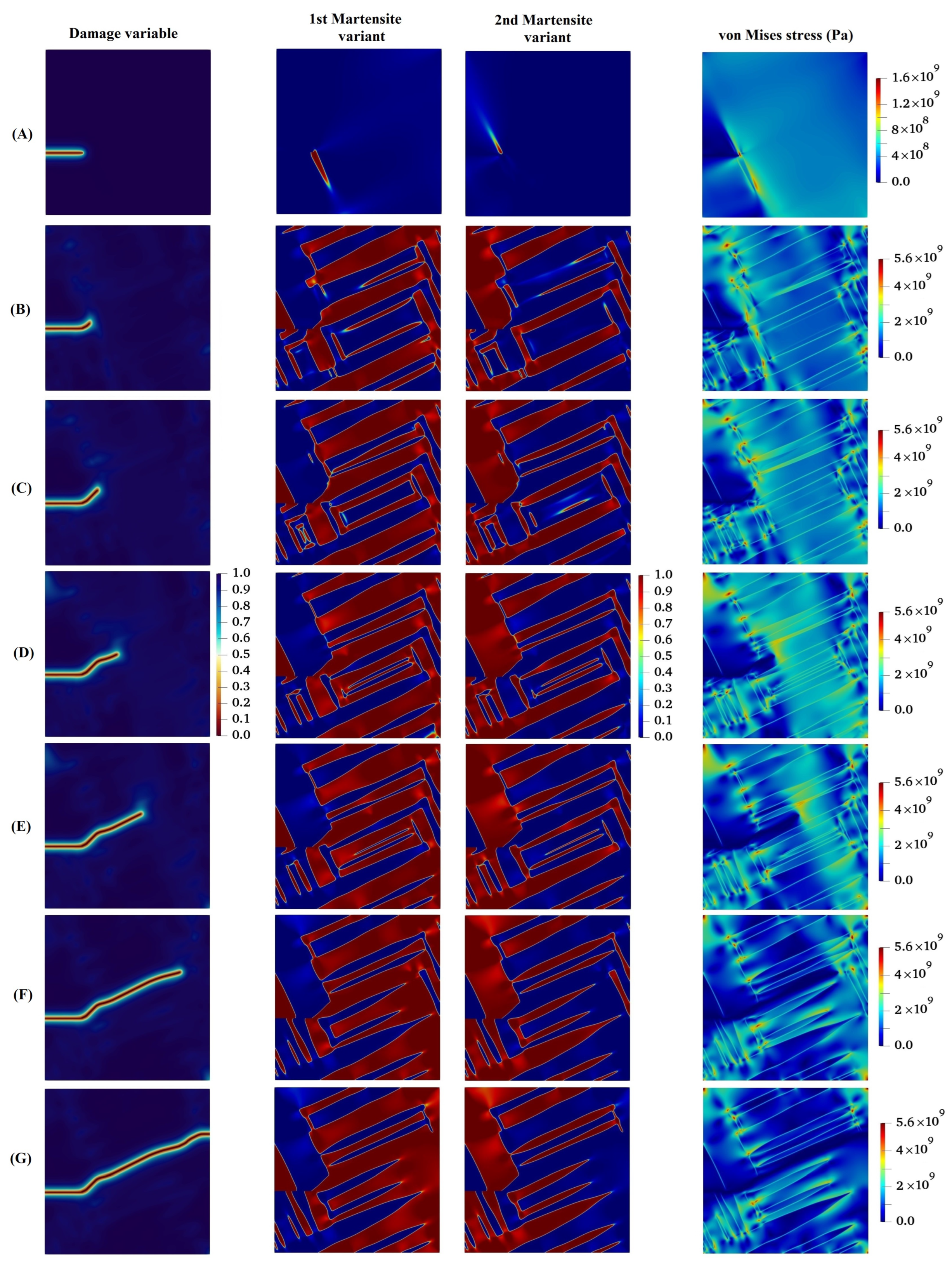
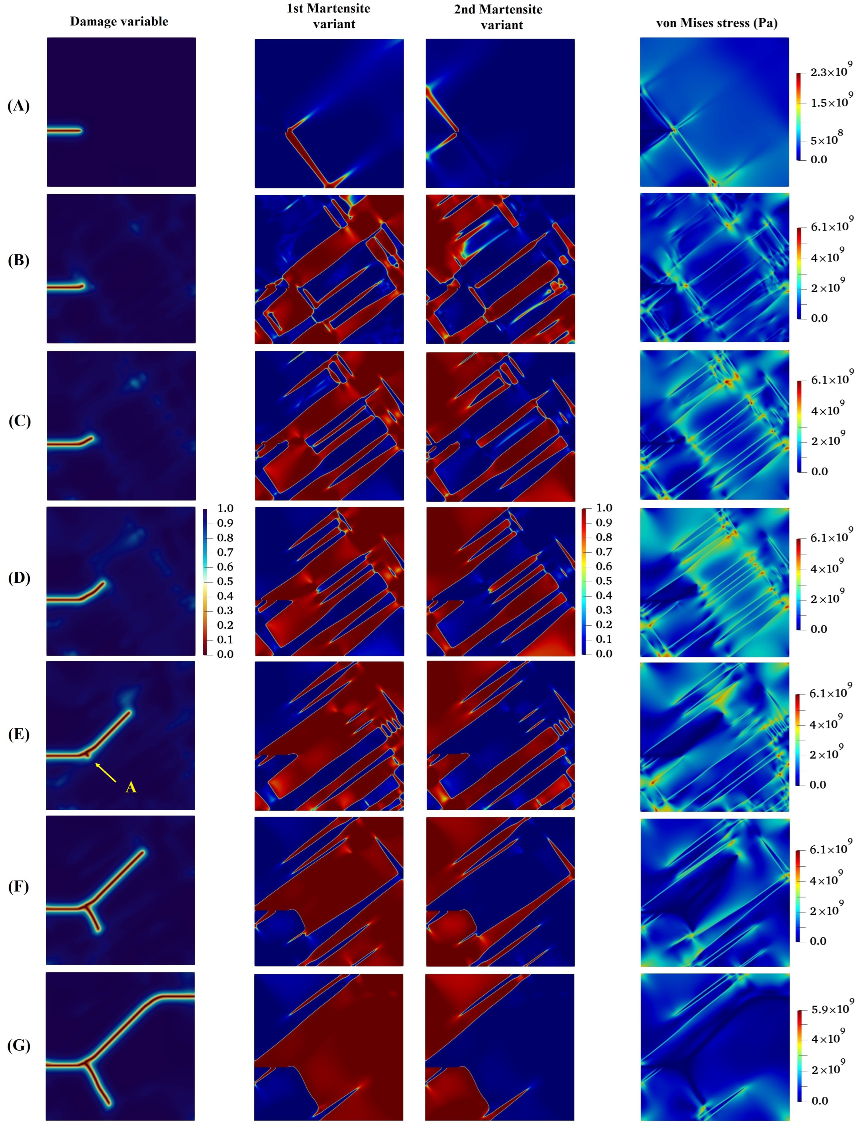
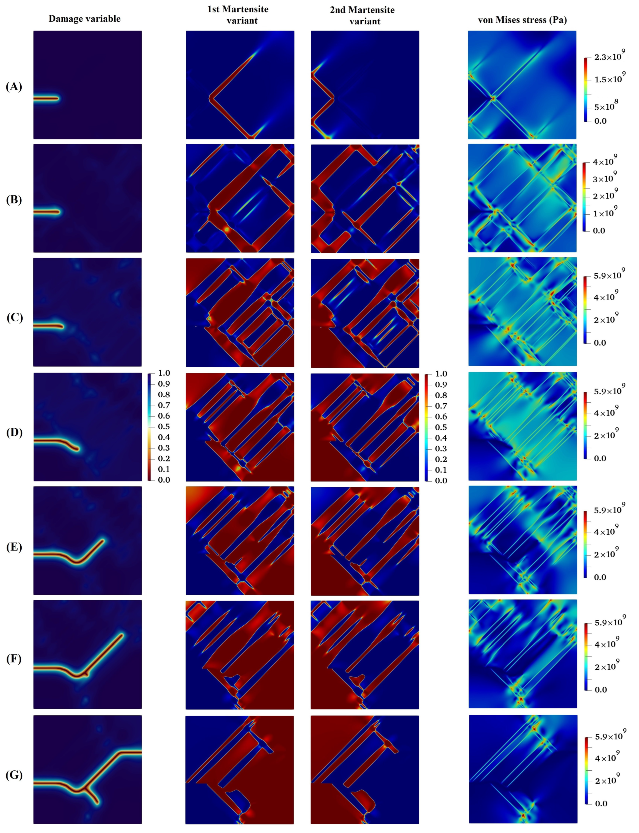
- Subsequent to the initial formation of the martensite variants, the initial crack propagates in such a way that its path mainly depends on the feature of martensite variant formations, the orientation and direction upon which the martensite plates are aligned, and the stress concentration between martensite plates.
- The results showed that for lattice orientation angles of 30 and 45, as the crack propagates between layers of two martensite variants, due to high stress concentration at the intersection of martensite variants on the crack surface, crack branching takes place.
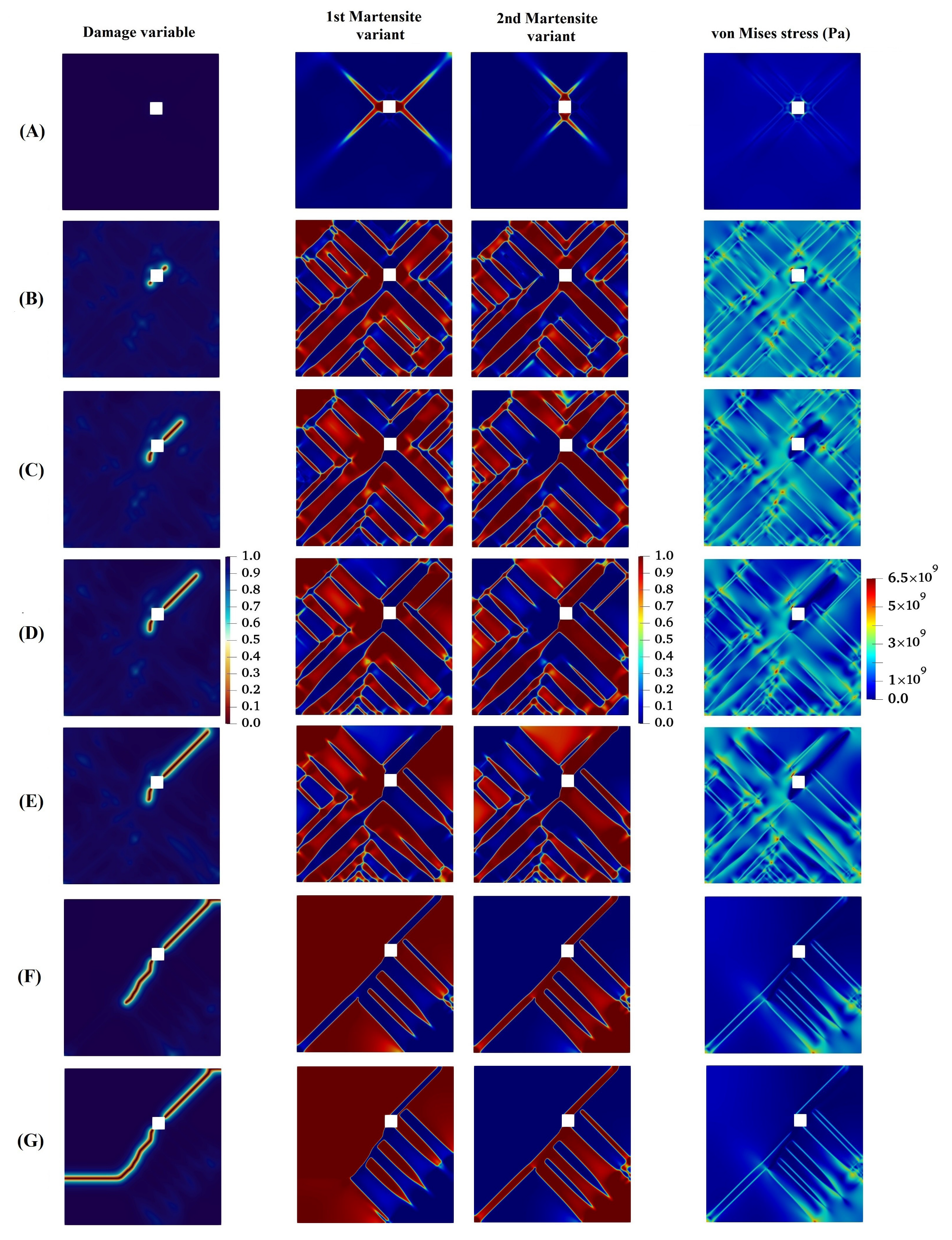
- For the lattice orientation angle of 90, it can be concluded that the crack tends to propagate between martensite variants, and at the same time, due to the high stress concentration formed at a location far from the main crack, a new crack initiates and grows. After that, the two cracks approach each other irrespective of the boundary between the martensite variants and eventually intersect.
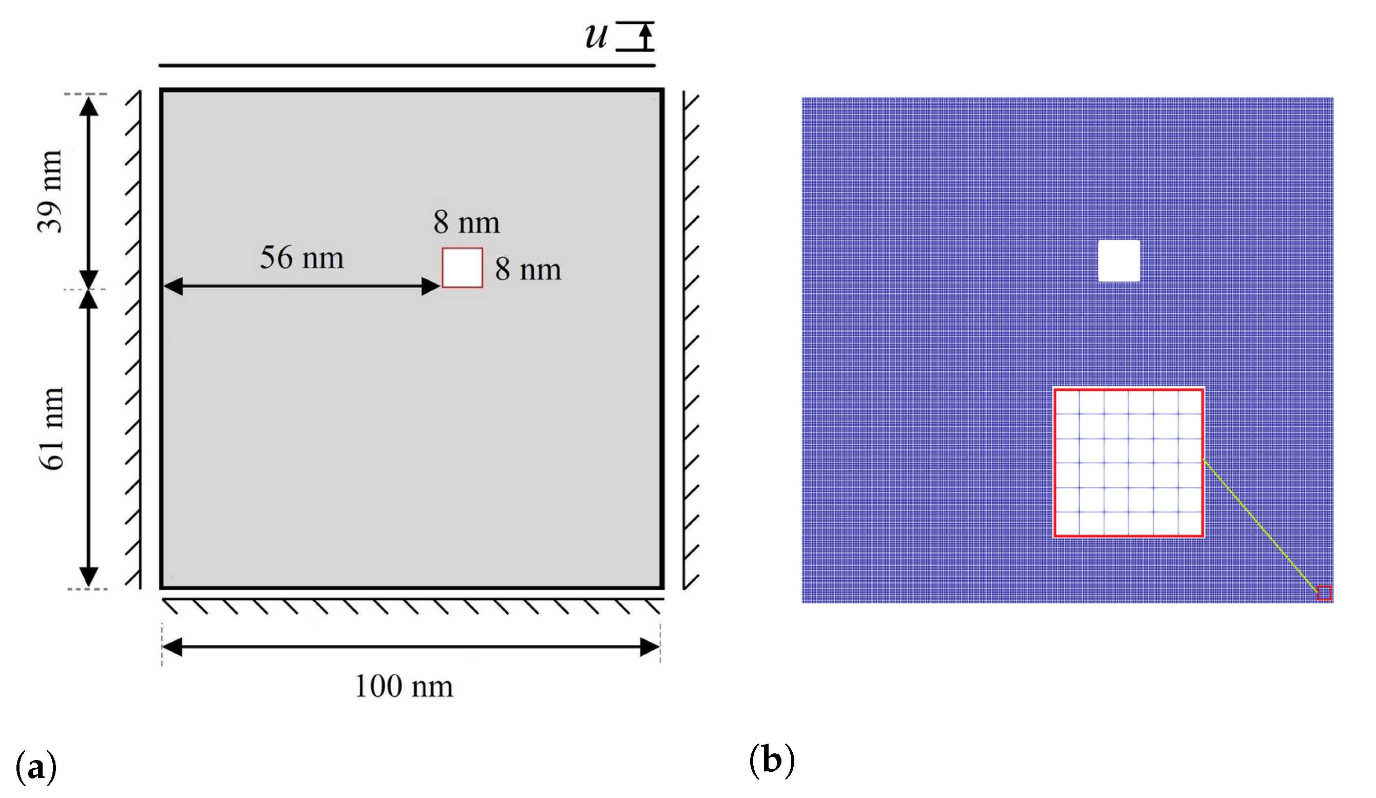
- The last example demonstrates one of the significant advantages of the phase-field method in comparison to other methodologies. This method, in contrast to the majority of other techniques, has the ability to identify places in the material with the potential to initiate cracks. The model illustrates that martensitic phase change can start even in the absence of martensitic nuclei when subjected to stress concentrations due to geometric heterogeneity. Then, the phase change can be extended to the entire component. The fracture also commences nucleation and propagates through the material, and this process continues under a fully coupled martensitic transformation to final failure.
Author Contributions
Funding
Institutional Review Board Statement
Informed Consent Statement
Data Availability Statement
Conflicts of Interest
References
- Chung, D.D. Functional Materials: Electrical, Dielectric, Electromagnetic, Optical and Magnetic Applications; World Scientific: Singapore, 2021; Volume 4. [Google Scholar]
- Folland, C.; Karl, T.; Christy, J.; Clarke, R.; Gruza, G.; Jouzel, J.; Mann, M.; Oerlemans, J.; Salinger, M.; Wang, S.; et al. Observed climate variability and change. Clim. Chang. 2001, 2001, 99. [Google Scholar]
- Sluiter, M. First principles in modelling phase transformations in steels. In Phase Transformations in Steels; Elsevier: Amsterdam, The Netherlands, 2012; pp. 365–404. [Google Scholar]
- Pereloma, E.; Edmonds, D.V. Phase Transformations in Steels: Diffusionless Transformations, High Strength Steels, Modelling and Advanced Analytical Techniques; Elsevier: Amsterdam, The Netherlands, 2012. [Google Scholar]
- Chen, L.Q. Phase-field models for microstructure evolution. Annu. Rev. Mater. Res. 2002, 32, 113–140. [Google Scholar]
- Armandei, M.; Burgos, D.F.S.; Ruggieri, C.; Tomba, S.L.G.; da Silva, N.d.S. J estimation based on regression machine learning applied to circumferential surface clad pipes with V groove weld. Int. J. Press. Vessel. Pip. 2022, 197, 104631. [Google Scholar] [CrossRef]
- Alves, C.L.M.; Rezende, J.; Senk, D.; Kundin, J. Phase-field simulation of peritectic steels solidification with transformation-induced elastic effect. J. Mater. Res. Technol. 2020, 9, 3805–3816. [Google Scholar] [CrossRef]
- Borzabadi Farahani, E.; Sobhani Aragh, B.; Mansur, W. Three-dimensional finite element modelling of welding residual stresses of medium carbon steel pipes with consideration of solid-state austenite-martensite transformation and post-weld heat treatment. Proc. Inst. Mech. Eng. 2019, 233, 2352–2364. [Google Scholar] [CrossRef]
- Boettinger, W.J.; Warren, J.A.; Beckermann, C.; Karma, A. Phase-field simulation of solidification. Annu. Rev. Mater. Res. 2002, 32, 163–194. [Google Scholar] [CrossRef]
- Chen, C.; Yang, X. Efficient numerical scheme for a dendritic solidification phase field model with melt convection. J. Comput. Phys. 2019, 388, 41–62. [Google Scholar] [CrossRef]
- Kim, K.; Roy, A.; Gururajan, M.; Wolverton, C.; Voorhees, P.W. First-principles/Phase-field modeling of θ precipitation in Al-Cu alloys. Acta Mater. 2017, 140, 344–354. [Google Scholar] [CrossRef]
- Ma, Y.; Yao, X.; Hao, W.; Chen, L.; Fang, D. Oxidation mechanism of ZrB2/SiC ceramics based on phase-field model. Compos. Sci. Technol. 2012, 72, 1196–1202. [Google Scholar]
- Toghraee, A.; Asle Zaeem, M. Oxidation Induced Stresses in High-Temperature Oxidation of Steel: A Multiphase Field Study. Metals 2020, 10, 801. [Google Scholar]
- Perumal, R.; Amos, P.K.; Selzer, M.; Nestler, B. Phase-field study on the formation of first-neighbour topological clusters during the isotropic grain growth. Comput. Mater. Sci. 2017, 140, 209–223. [Google Scholar] [CrossRef]
- Kundin, J.; Almeida, R.S.; Salama, H.; Farhandi, H.; Tushtev, K.; Rezwan, K. Phase-field simulation of abnormal anisotropic grain growth in polycrystalline ceramic fibers. Comput. Mater. Sci. 2020, 185, 109926. [Google Scholar] [CrossRef]
- Cahn, J.W.; Hilliard, J.E. Free energy of a nonuniform system. I. Interfacial free energy. J. Chem. Phys. 1958, 28, 258–267. [Google Scholar] [CrossRef]
- Allen, S.M.; Cahn, J.W. A microscopic theory for antiphase boundary motion and its application to antiphase domain coarsening. Acta Metall. 1979, 27, 1085–1095. [Google Scholar] [CrossRef]
- Landau, L.D. Collected Papers of LD Landau; Elsevier: Pergamon, Turkey, 1965. [Google Scholar]
- Cherkaoui, M.; Berveiller, M. Micromechanical modeling of the martensitic transformation induced plasticity in steels. Smart Mater. Struct. 2000, 9, 592. [Google Scholar] [CrossRef]
- Levitas, V.I.; Preston, D.L. Three-dimensional Landau theory for multivariant stress-induced martensitic phase transformations. I. Austenite martensite. Phys. Rev. B 2002, 66, 134206. [Google Scholar] [CrossRef]
- Levitas, V.I.; Preston, D.L. Three-dimensional Landau theory for multivariant stress-induced martensitic phase transformations. II. Multivariant phase transformations and stress space analysis. Phys. Rev. B 2002, 66, 134207. [Google Scholar] [CrossRef]
- Wang, Y.; Khachaturyan, A. Three-dimensional field model and computer modeling of martensitic transformations. Acta Mater. 1997, 45, 759–773. [Google Scholar] [CrossRef]
- Wang, Y.; Khachaturyan, A.G. Multi-scale phase field approach to martensitic transformations. Mater. Sci. Eng. A 2006, 438, 55–63. [Google Scholar] [CrossRef]
- Zhang, W.; Jin, Y.; Khachaturyan, A. Phase field microelasticity modeling of heterogeneous nucleation and growth in martensitic alloys. Acta Mater. 2007, 55, 565–574. [Google Scholar] [CrossRef]
- Yeddu, H.K.; Malik, A.; Ågren, J.; Amberg, G.; Borgenstam, A. Three-dimensional phase-field modeling of martensitic microstructure evolution in steels. Acta Mater. 2012, 60, 1538–1547. [Google Scholar] [CrossRef]
- Malik, A.; Yeddu, H.K.; Amberg, G.; Borgenstam, A.; Ågren, J. Three dimensional elasto-plastic phase field simulation of martensitic transformation in polycrystal. Mater. Sci. Eng. A 2012, 556, 221–232. [Google Scholar] [CrossRef]
- Khachaturyan, A.G. Theory of Structural Transformations in Solids; Courier Corporation: Chelmsford, MA, USA, 2013. [Google Scholar]
- Guo, X.; Shi, S.Q.; Ma, X. Elastoplastic phase field model for microstructure evolution. Appl. Phys. Lett. 2005, 87, 221910. [Google Scholar] [CrossRef]
- Schmitt, R.; Müller, R.; Kuhn, C.; Urbassek, H.M. A phase field approach for multivariant martensitic transformations of stable and metastable phases. Arch. Appl. Mech. 2013, 83, 849–859. [Google Scholar] [CrossRef]
- Mamivand, M.; Zaeem, M.A.; El Kadiri, H.; Chen, L.Q. Phase field modeling of the tetragonal-to-monoclinic phase transformation in zirconia. Acta Mater. 2013, 61, 5223–5235. [Google Scholar] [CrossRef]
- Xie, X.; Kang, G.; Kan, Q.; Yu, C.; Peng, Q. Phase field modeling for cyclic phase transition of NiTi shape memory alloy single crystal with super-elasticity. Comput. Mater. Sci. 2018, 143, 212–224. [Google Scholar] [CrossRef]
- Babaei, H.; Basak, A.; Levitas, V.I. Algorithmic aspects and finite element solutions for advanced phase field approach to martensitic phase transformation under large strains. Comput. Mech. 2019, 64, 1177–1197. [Google Scholar] [CrossRef]
- Sun, Y.; Luo, J.; Zhu, J.; Zhou, K. A non-isothermal phase field study of the shape memory effect and pseudoelasticity of polycrystalline shape memory alloys. Comput. Mater. Sci. 2019, 167, 65–76. [Google Scholar] [CrossRef]
- Cissé, C.; Zaeem, M.A. A phase-field model for non-isothermal phase transformation and plasticity in polycrystalline yttria-stabilized tetragonal zirconia. Acta Mater. 2020, 191, 111–123. [Google Scholar] [CrossRef]
- Javanbakht, M.; Ghaedi, M.S. Nanovoid induced multivariant martensitic growth under negative pressure: Effect of misfit strain and temperature on PT threshold stress and phase evolution. Mech. Mater. 2020, 151, 103627. [Google Scholar] [CrossRef]
- Farahani, E.B.; Aragh, B.S.; Voges, J.; Juhre, D. On the crack onset and growth in martensitic structures; a phase-field approach. Int. J. Mech. Sci. 2021, 194, 106187. [Google Scholar] [CrossRef]
- Bulbich, A. Nucleation on the crack tip and transformation toughness in crystals undergoing structural phase transitions. J. Mater. Sci. 1992, 27, 1070–1080. [Google Scholar] [CrossRef]
- Stump, D.M.; Budiansky, B. Crack-growth resistance in transformation-toughened ceramics. Int. J. Solids Struct. 1989, 25, 635–646. [Google Scholar] [CrossRef]
- Creuziger, A.; Bartol, L.; Gall, K.; Crone, W. Fracture in single crystal NiTi. J. Mech. Phys. Solids 2008, 56, 2896–2905. [Google Scholar] [CrossRef]
- Ambati, M.; Gerasimov, T.; De Lorenzis, L. A review on phase-field models of brittle fracture and a new fast hybrid formulation. Comput. Mech. 2015, 55, 383–405. [Google Scholar] [CrossRef]
- Hakim, V.; Karma, A. Laws of crack motion and phase-field models of fracture. J. Mech. Phys. Solids 2009, 57, 342–368. [Google Scholar] [CrossRef]
- Aranson, I.; Kalatsky, V.; Vinokur, V. Continuum field description of crack propagation. Phys. Rev. Lett. 2000, 85, 118. [Google Scholar] [CrossRef]
- Spatschek, R.; Brener, E.; Karma, A. Phase field modeling of crack propagation. Philos. Mag. 2011, 91, 75–95. [Google Scholar] [CrossRef]
- Rabczuk, T. Computational methods for fracture in brittle and quasi-brittle solids: State-of-the-art review and future perspectives. Int. Sch. Res. Not. 2013, 2013, 849231. [Google Scholar] [CrossRef]
- Miehe, C.; Hofacker, M.; Welschinger, F. A phase field model for rate-independent crack propagation: Robust algorithmic implementation based on operator splits. Comput. Methods Appl. Mech. Eng. 2010, 199, 2765–2778. [Google Scholar] [CrossRef]
- Kuhn, C.; Müller, R. A continuum phase field model for fracture. Eng. Fract. Mech. 2010, 77, 3625–3634. [Google Scholar] [CrossRef]
- Amor, H.; Marigo, J.J.; Maurini, C. Regularized formulation of the variational brittle fracture with unilateral contact: Numerical experiments. J. Mech. Phys. Solids 2009, 57, 1209–1229. [Google Scholar] [CrossRef]
- Borden, M.J.; Hughes, T.J.; Landis, C.M.; Verhoosel, C.V. A higher-order phase-field model for brittle fracture: Formulation and analysis within the isogeometric analysis framework. Comput. Methods Appl. Mech. Eng. 2014, 273, 100–118. [Google Scholar] [CrossRef]
- Bourdin, B.; Francfort, G.A.; Marigo, J.J. The variational approach to fracture. J. Elast. 2008, 91, 5–148. [Google Scholar] [CrossRef]
- Makvandi, R.; Duczek, S.; Juhre, D. A phase-field fracture model based on strain gradient elasticity. Eng. Fract. Mech. 2019, 220, 106648. [Google Scholar] [CrossRef]
- De Lorenzis, L.; Gerasimov, T. Numerical Implementation of Phase-Field Models of Brittle Fracture. In Modeling in Engineering Using Innovative Numerical Methods for Solids and Fluids; Springer: Berlin/Heidelberg, Germany, 2020; pp. 75–101. [Google Scholar]
- Lifshitz, E.M.; Pitaevskii, L.P. Statistical Physics: Theory of the Condensed State; Elsevier: Amsterdam, The Netherlands, 2013; Volume 9. [Google Scholar]
- Francfort, G.A.; Marigo, J.J. Revisiting brittle fracture as an energy minimization problem. J. Mech. Phys. Solids 1998, 46, 1319–1342. [Google Scholar] [CrossRef]
- Clayton, J.; Knap, J. Phase field modeling and simulation of coupled fracture and twinning in single crystals and polycrystals. Comput. Methods Appl. Mech. Eng. 2016, 312, 447–467. [Google Scholar] [CrossRef]
- Schmitt, R.; Kuhn, C.; Skorupski, R.; Smaga, M.; Eifler, D.; Müller, R. A combined phase field approach for martensitic transformations and damage. Arch. Appl. Mech. 2015, 85, 1459–1468. [Google Scholar] [CrossRef]
- Jafarzadeh, H.; Levitas, V.I.; Farrahi, G.H.; Javanbakht, M. Phase field approach for nanoscale interactions between crack propagation and phase transformation. Nanoscale 2019, 11, 22243–22247. [Google Scholar] [CrossRef]
- Zhao, T.; Zhu, J.; Luo, J. Study of crack propagation behavior in single crystalline tetragonal zirconia with the phase field method. Eng. Fract. Mech. 2016, 159, 155–173. [Google Scholar] [CrossRef]
- Amirian, B.; Jafarzadeh, H.; Abali, B.E.; Reali, A.; Hogan, J.D. Phase-field approach to evolution and interaction of twins in single crystal magnesium. Comput. Mech. 2022, 70, 803–818. [Google Scholar] [CrossRef] [PubMed]
- Mura, T. Micromechanics of Defects in Solids; Springer Science & Business Media: Berlin/Heidelberg, Germany, 2013. [Google Scholar]
- Schlüter, A.; Willenbücher, A.; Kuhn, C.; Müller, R. Phase field approximation of dynamic brittle fracture. Comput. Mech. 2014, 54, 1141–1161. [Google Scholar] [CrossRef]
- Mamivand, M.; Zaeem, M.A.; El Kadiri, H. Phase field modeling of stress-induced tetragonal-to-monoclinic transformation in zirconia and its effect on transformation toughening. Acta Mater. 2014, 64, 208–219. [Google Scholar] [CrossRef]
- Stolarz, J.; Baffie, N.; Magnin, T. Fatigue short crack behaviour in metastable austenitic stainless steels with different grain sizes. Mater. Sci. Eng. A 2001, 319, 521–526. [Google Scholar] [CrossRef]


Publisher’s Note: MDPI stays neutral with regard to jurisdictional claims in published maps and institutional affiliations. |
© 2022 by the authors. Licensee MDPI, Basel, Switzerland. This article is an open access article distributed under the terms and conditions of the Creative Commons Attribution (CC BY) license (https://creativecommons.org/licenses/by/4.0/).
Share and Cite
Farahani, E.B.; Aragh, B.S.; Juhre, D. Interplay of Fracture and Martensite Transformation in Microstructures: A Coupled Problem. Materials 2022, 15, 6744. https://doi.org/10.3390/ma15196744
Farahani EB, Aragh BS, Juhre D. Interplay of Fracture and Martensite Transformation in Microstructures: A Coupled Problem. Materials. 2022; 15(19):6744. https://doi.org/10.3390/ma15196744
Chicago/Turabian StyleFarahani, Ehsan Borzabadi, Behnam Sobhani Aragh, and Daniel Juhre. 2022. "Interplay of Fracture and Martensite Transformation in Microstructures: A Coupled Problem" Materials 15, no. 19: 6744. https://doi.org/10.3390/ma15196744
APA StyleFarahani, E. B., Aragh, B. S., & Juhre, D. (2022). Interplay of Fracture and Martensite Transformation in Microstructures: A Coupled Problem. Materials, 15(19), 6744. https://doi.org/10.3390/ma15196744