

Strengthening of Full-Scale Laminated Veneer Lumber Beams with CFRP Sheets


Abstract
1. Introduction
1.1. State of the Art of Use a FRP Sheets as Reinforcement
- sheets bonded to the bottom and side surfaces with varying coverage of the latter, i.e., so-called U-type reinforcements;
- sheets bonded vertically or horizontally inside the cross-section;
- sheets completely covering the test piece, i.e., wrapping all sides with the FRP composite.
1.2. Objectives
2. Materials and Methods
2.1. Materials
2.1.1. Laminated Veneer Lumber (LVL)
2.1.2. CFRP Sheets
2.1.3. Adhesive
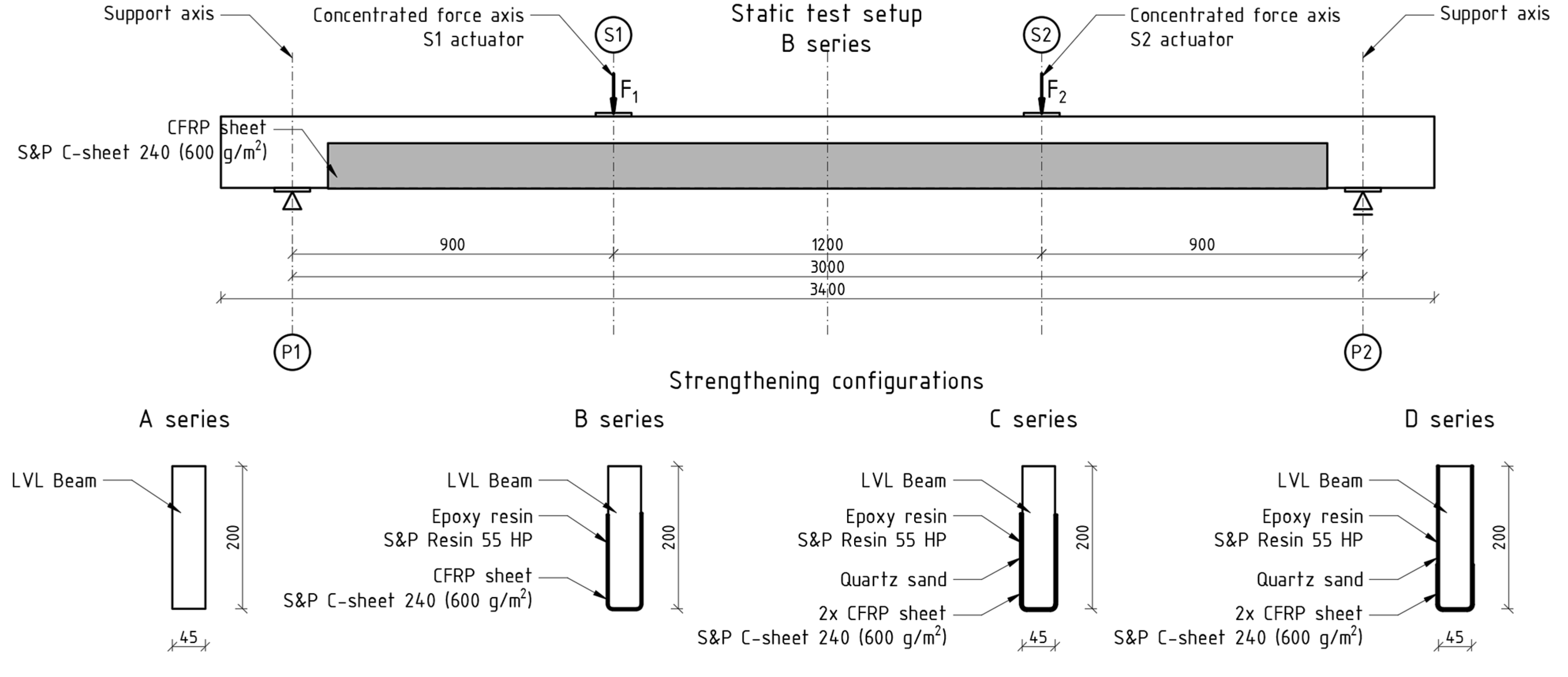
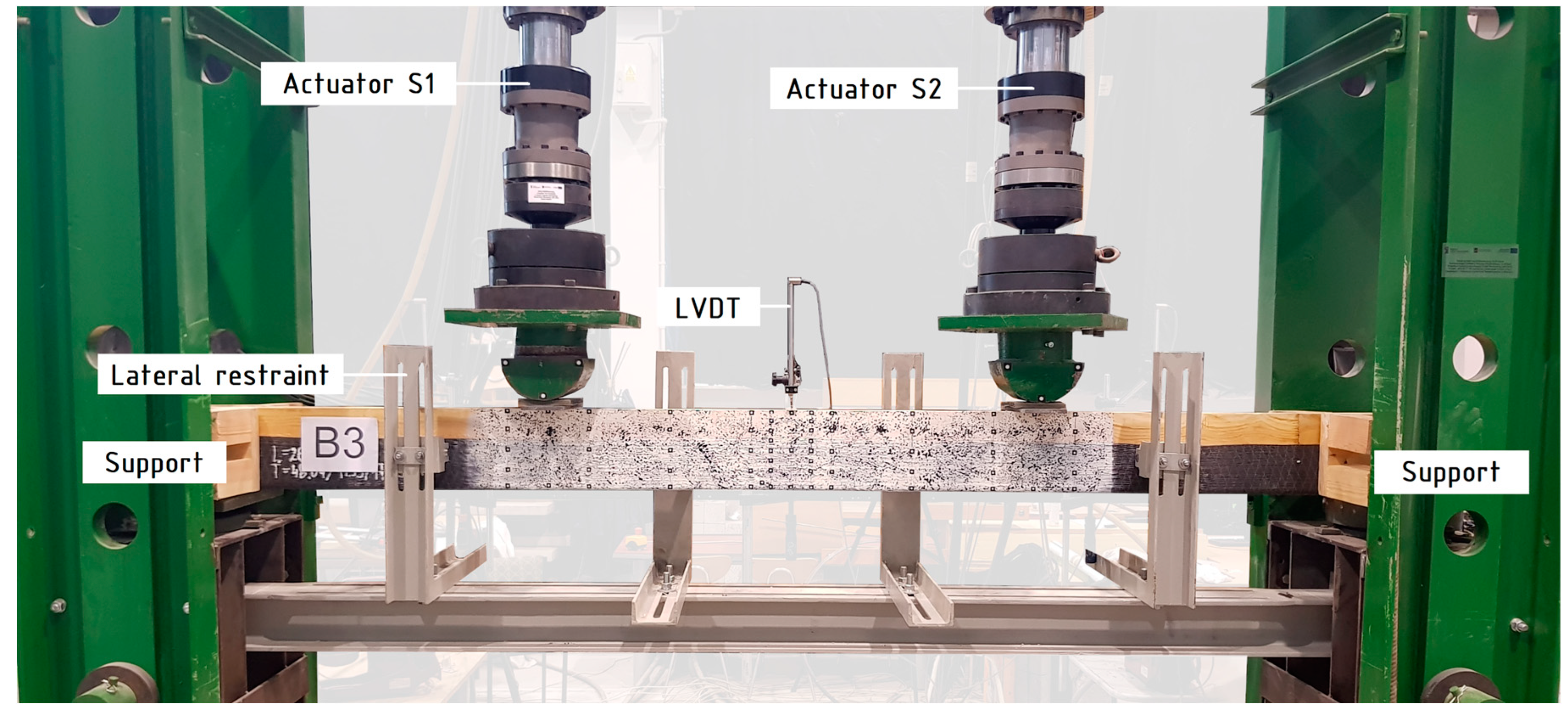
2.2. Methods
- A series—unreinforced beams;
- B series—beams reinforced with one layer of CFRP sheet bonded to the bottom side (reinforcement ratio, ρt = 1.11%);
- C series—beams reinforced with two layers of CFRP sheet bonded to the (reinforcement ratio, ρt = 2.22%);
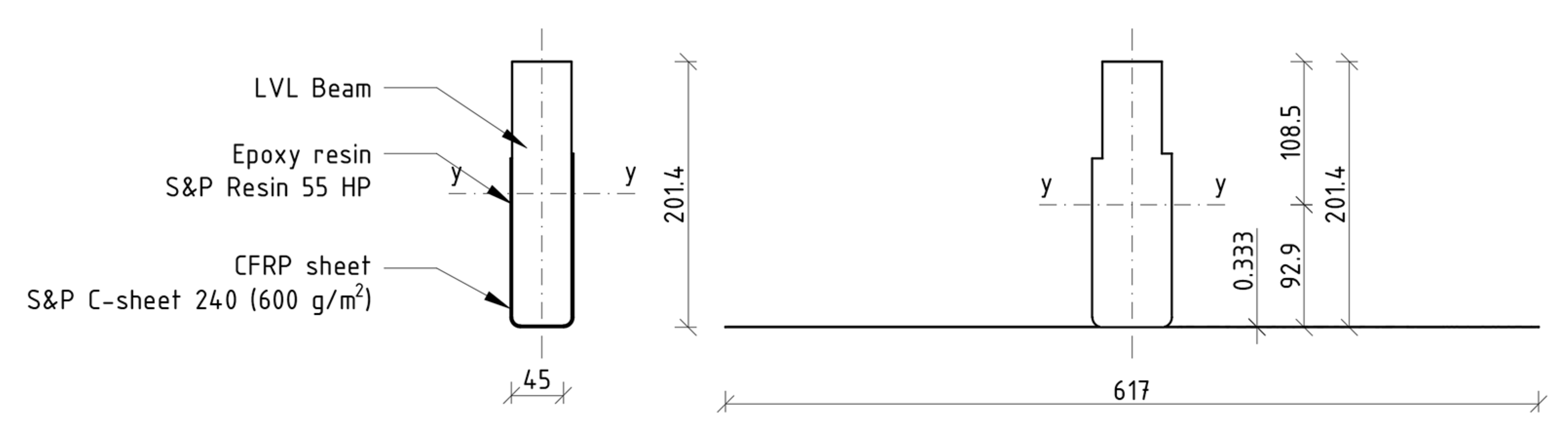
- D series—beams reinforced with two layers of CFRP sheet covering entire side surfaces with overlap in the tension zone (reinforcement ratio of tensile zone ρt = 1.48%; reinforcement ratio of compression zone ρc = 0.74%).
3. Results and Discussion
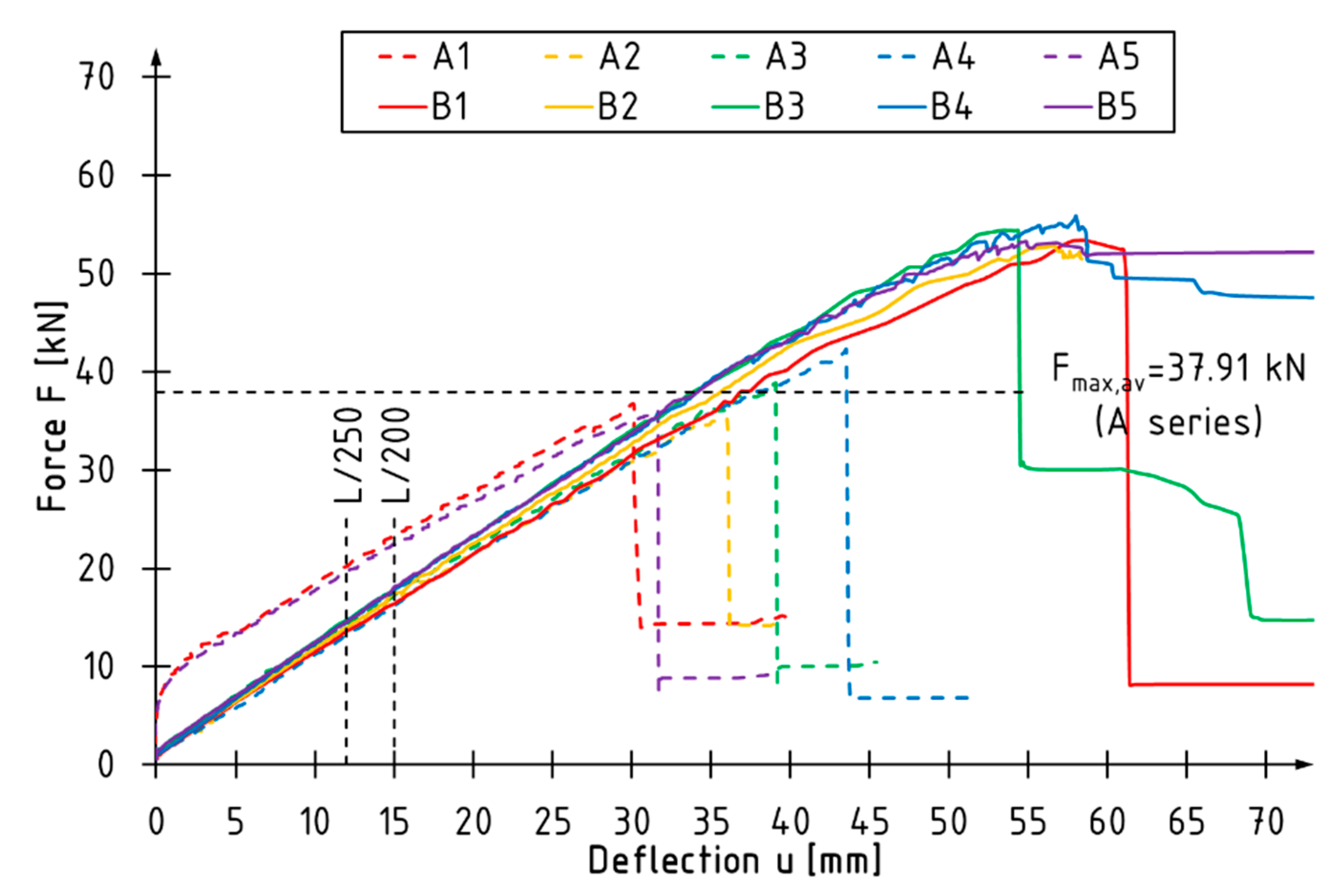
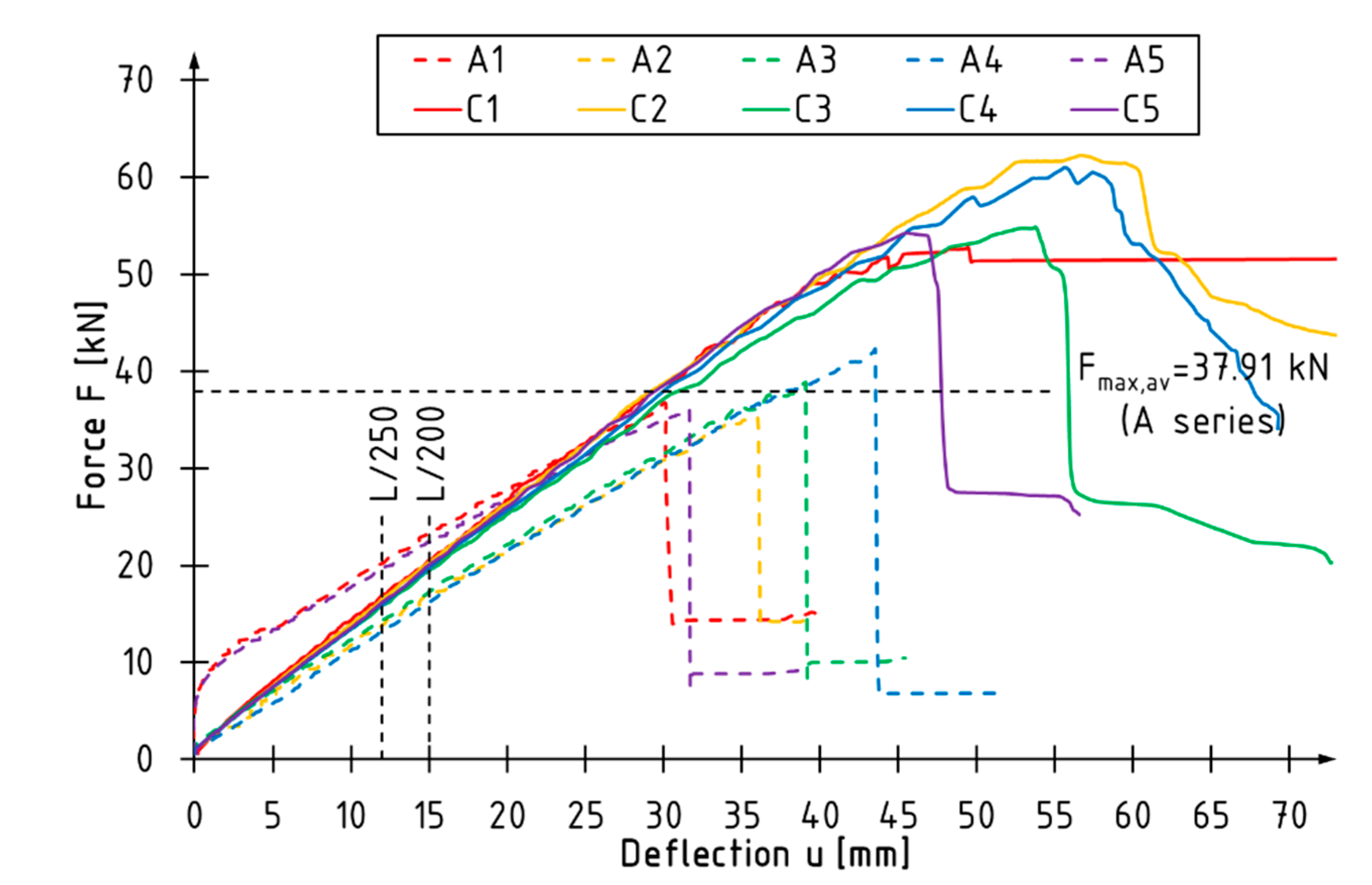
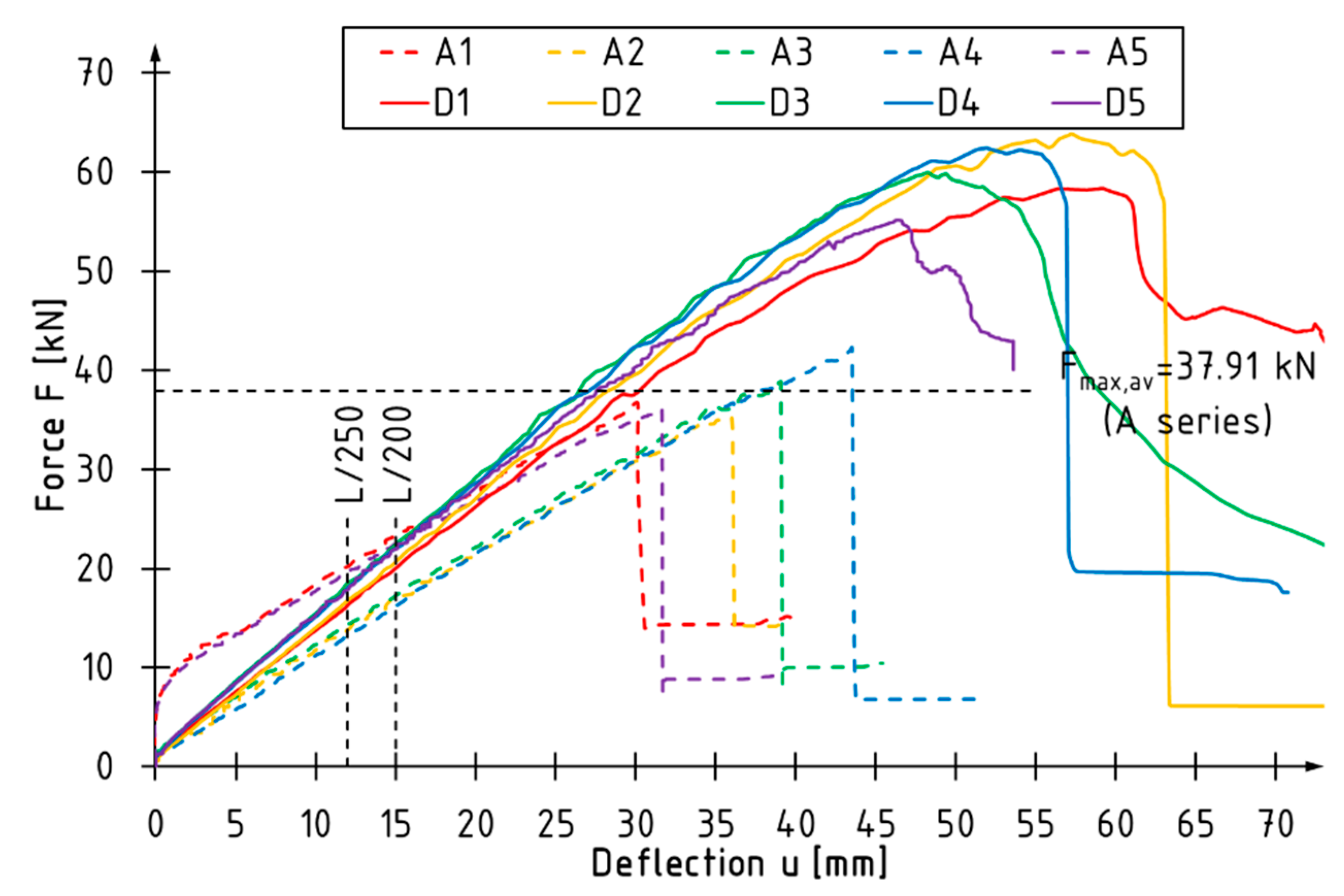
3.1. Bending Behavior and Load Bearing Capacity
3.2. Bending Stiffness
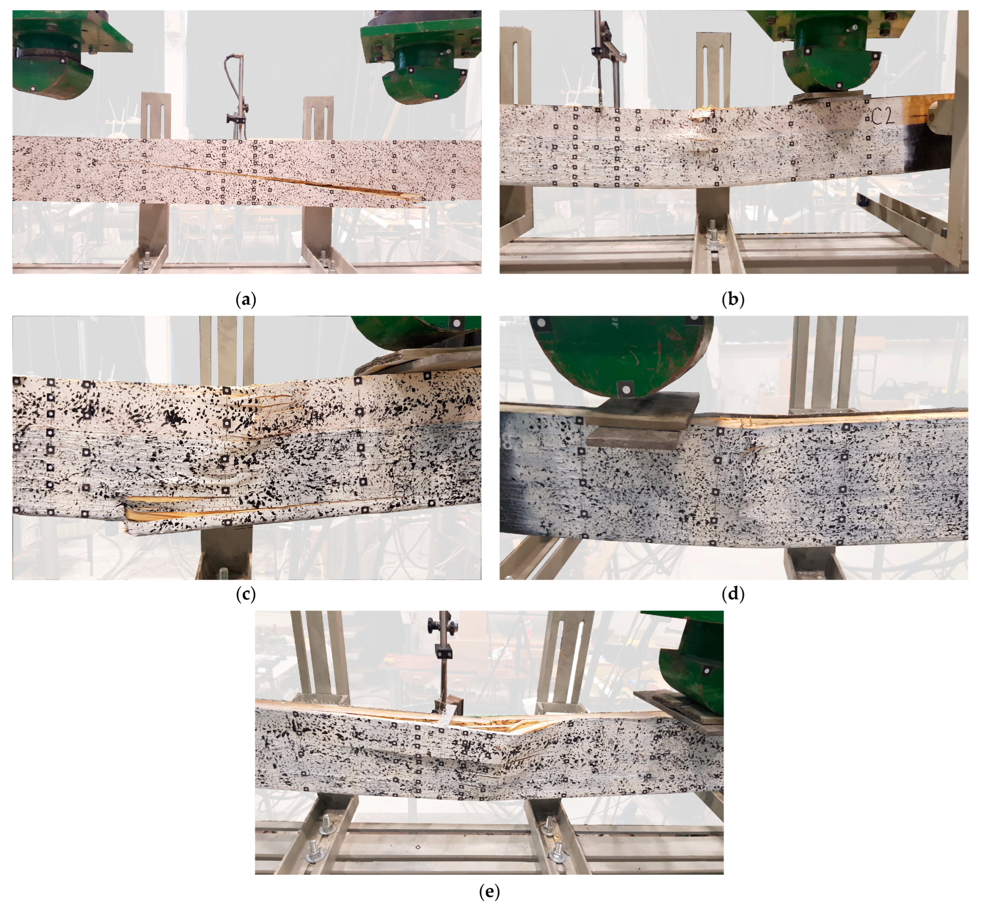
3.3. Failure Modes
- tension—failure of the reference beams resulted from the cracking of the veneer, which initiated in the outermost fibers stretched between the concentrated force points in the zone of maximum bending; this was also observed for weakly reinforced beams (see Figure 6a);
- compression—this is typical for elements reinforced with fibrous composites, with the following consequences: local buckling of the veneer layers and delamination; shearing and the accompanying displacement of the adjacent sections of the beam, or the penetration of one part of the veneer into another (see Figure 6b–e);
- delamination of the sheets perpendicular to the main direction; this usually occurs in the compressed zone and is associated with the breakage of the transversally arranged polyester fibers that stabilize the fibers arranged in the main direction (see Figure 6e);
- sheet shearing—i.e., carbon fiber cuts (perpendicular to the main direction of the sheet), related to the overlapping of adjacent veneer sections at the point of the failure initiation (Figure 6d);
- sheet delamination—breaks in the continuity of carbon fibers in the tensile zone, as observed during the tests of the B series beams (Figure 6b);
- lateral torsional buckling—a loss of stability.
3.4. Analysis of Modulus of Rupture
4. Conclusions
- The results of experimental research confirmed the validity of using fiber composites in the form of sheets as reinforcements for simply-supported LVL beams.
- The thicker the coverage of the side surface, the higher the load capacity of the beam. In the ultimate limit state of the load capacity, the highest percentage increase of load at failure was 58% for the D series beams reinforced with two layers of CFRP sheets covering the entire side surface of the beams. The use of two layers of sheets in the tensile zone only (C series) contributed to a 51% increase in the maximum load, while for one layer of CFRP sheet, the increase was 42%.
- A greater increase in bending strength and stiffness was observed in the full-sized beams than in those tested on a laboratory scale [39,40]. As the volume of the LVL beams increased, their bending strength decreased. CFRP sheets were also found to be more effective than aramid or glass fiber reinforced sheets [41]. Additionally, CFRP sheets have better mechanical properties than to AFRP and GFRP sheets.
- The highest percentage increase in bending stiffness was observed for the C and D series beams, amounting to 31% and 43%, respectively. The smallest increase, amounting to 15%, was observed for the B series beams.
- With the increase of the cross-section reinforcement thickness and the side surface thickness, the percentage increase of the deflection at the maximum force in relation to the reference beams decreased. The deflection increment for the B series beams was 42%, and for the D series beams 33%. Failure initiation signs occurred at a lower deflection value.
- There was a change in the failure mode, i.e., the brittle fracturing observed with the reference beams did not occur. The load-bearing fibers broke in cases where one layer of CFRP sheet was used. Regardless of the number of fabric layers, delamination occurred as a result of breaking the polyester stabilizing fibers in the compressed zone.
- The use of composite sheets as reinforcements is justified to increase safety by eliminating the influence of possible defects in the structure of glued laminated wood with veneers.
- The proposed reinforcement method is simple and quick to apply. It does not require any special equipment and can be performed by two people.
- The proposed reinforcement schemes can be used for existing structures.
- In further tests, the use of additional (structural) reinforcements should be considered to prevent the delamination of the sheets arranged transversely to the main reinforcement direction in the compression zone.
Author Contributions
Funding
Institutional Review Board Statement
Informed Consent Statement
Acknowledgments
Conflicts of Interest
References
- Jasieńko, J. Połączenia Klejowe i Inżynierskie w Naprawie, Konserwacji i Wzmacnianiu Zabytkowych Konstrukcji Drewnianych; Dolnośląskie Wydawnictwo Edukacyjne: Wroclaw, Poland, 2003. [Google Scholar]
- Jasieńko, J. Połączenia Klejowe w Rehabilitacji i Wzmacnianiu Zginanych Belek Drewnianych; Oficyna Wydawnicza Politechniki Wrocławskiej: Wroclaw, Poland, 2002. [Google Scholar]
- Micelli, F.; Scialpi, V.; La Tegola, A. Flexural reinforcement of glulam timber beams and joints with carbon fiber-reinforced polymer rods. J. Compos. Constr. 2005, 9, 337–347. [Google Scholar] [CrossRef]
- Mirski, R.; Kuliński, M.; Dziurka, D.; Thomas, M.; Antonowicz, R. Strength Properties of Structural Glulam Elements from Pine (Pinus sylvestris L.) Timber Reinforced in the Tensile Zone with Steel and Basalt Rods. Materials 2021, 14, 2574. [Google Scholar] [CrossRef] [PubMed]
- Li, Y.-F.; Tsai, M.-J.; Wei, T.-F.; Wang, W.C. A study on wood beams strengthened by FRP composite materials. Constr. Build. Mater. 2014, 62, 118–125. [Google Scholar] [CrossRef]
- Righetti, L.; Corradi, M.; Borri, A. Basalt FRP Spike Repairing of Wood Beams. Fibers 2015, 3, 323–337. [Google Scholar] [CrossRef]
- Yang, H.; Liu, W.; Lu, W.; Zhu, S.; Geng, Q. Flexural behavior of FRP and steel reinforced glulam beams: Experimental and theoretical evaluation. Constr. Build. Mater. 2016, 106, 550–563. [Google Scholar] [CrossRef]
- Yeboah, D.; Gkantou, M. Investigation of flexural behavior of structural timber beams strengthened with NSM basalt and glass FRP bars. Structures 2021, 33, 390–405. [Google Scholar] [CrossRef]
- Kliger, R.; Johansson, M.; Crocetti, R.; Al-Emrani, M. Strengthening timber with CFRP or steel plates—Short and long-term performance. In Proceedings of the World Conference on Timber Engineering (WCTE08), Miyazaki, Japan, 2–5 June 2008. [Google Scholar]
- D’Ambrisi, A.; Focacci, F.; Luciano, R. Experimental investigation on flexural behavior of timber beams repaired with CFRP plates. Comp. Struct. 2014, 108, 720–728. [Google Scholar] [CrossRef]
- Nowak, T.P.; Jasieńko, J.; Czepiżak, D. Experimental tests and numerical analysis of historic bent timber elements reinforced with CFRP strips. Constr. Build. Mater. 2013, 40, 197–206. [Google Scholar] [CrossRef]
- Dewey, J.; Burry, M.; Tuladhar, R.; Sivakugan, N.; Pandey, G.; Stephenson, D. Strengthening and rehabilitation of deteriorated timber bridge girders. Constr. Build. Mater. 2018, 185, 302–309. [Google Scholar] [CrossRef]
- De la Rosa García, P.; Escamilla, A.C.; Nieves González García, M. Bending reinforcement of timber beams with composite carbon fiber and basalt fiber materials. Compos. B Eng. 2013, 55, 528–536. [Google Scholar] [CrossRef]
- Sokołowski, P.; Kossakowski, P.G. Estimation of the modulus fir wood reinforced with PBO fiber mesh. Arch. Civ. Eng. 2018, 64, 105–121. [Google Scholar] [CrossRef]
- Wdowiak-Postulak, A.; Świt, G. Behavior of glulam beams strengthened in bending with BFRP fabrics. Civ. Environ. Eng. Rep. 2021, 2, 16. [Google Scholar] [CrossRef]
- Nabati, A.; Ghazijahani, T.G.; Valipour, H.R. Innovative flitch sandwich beams with steel core under four-point bending. Eng. Sturct. 2021, 233, 111724. [Google Scholar] [CrossRef]
- Nadir, Y.; Nagarajan, P.; Mohammed, A.; Arif, M.M. Flexural stiffness and strength enhancement of horizontally glued laminated wood beams with GFRP and CFRP composite sheets. Constr. Build. Mater. 2016, 112, 547–555. [Google Scholar] [CrossRef]
- Triantafillou, T.C.; Deskovic, N. Prestressed FRP sheets as external reinforcement of wood members. J. Struct. Eng. 1992, 118, 1270–1283. [Google Scholar] [CrossRef]
- Chen, S.; Wei, Y.; Peng, D.; Zhao, K.; Hu, Y. Experimental investigation of timber beams strengthened by bamboo scrimber with anchorage structure. Structures 2021, 33, 1–11. [Google Scholar] [CrossRef]
- Andor, K.; Lengyel, A.; Polgár, R.; Fodor, T.; Karácsonyi, Z. Experimental and statistical analysis of spruce timber beams reinforced with CFRP fabric. Constr. Build. Mater. 2015, 99, 200–207. [Google Scholar] [CrossRef]
- Fiorelli, J.; Dias, A.A. Analysis of the Strength and Stiffness of Timber Beams Reinforced with Carbon Fiber and Glass Fiber. Mater. Res. 2003, 6, 193–202. [Google Scholar] [CrossRef]
- Sviták, M.; Barcík, Š.; Ryspler, J. Application of carbon fibers on wood beams. Acta Fac. Xylologiae Zvolen 2013, 55, 33–42. [Google Scholar]
- Li, Y.-F.; Xie, Y.-M.; Tsai, M.J. Enhancement of the flexural performance of retrofitted wood beams using CFRP composite sheets. Constr. Build. Mater. 2009, 23, 411–422. [Google Scholar] [CrossRef]
- Kossakowski, P. Load-bearing capacity of wooden beams reinforced with composite sheets. Struct. Environ. 2011, 4, 14–22. [Google Scholar]
- Basterra, L.A.; Balmori, J.A.; Morillas, L.; Acuña, L.; Casado, M. Internal reinforcement of laminated duo beams of low-grade timber with GFRP sheets. Constr. Build. Mater. 2017, 154, 914–920. [Google Scholar] [CrossRef]
- Gezer, H.; Aydemir, B. The effect of the wrapped carbon fiber reinforced polymer material on fir and pine woods. Mater. Des. 2010, 31, 3564–3567. [Google Scholar] [CrossRef]
- Gómez, E.P.; González, M.N.; Hosokawa, K.; Cobo, A. Experimental study of the flexural behavior of timber beams reinforced with different kinds of FRP and metallic fibers. Compos. Struct. 2019, 213, 308–316. [Google Scholar] [CrossRef]
- Vahedian, A.; Shrestha, R.; Crews, K. Experimental and analytical investigation on CFRP strengthened glulam laminated timber beams: Full-scale experiments. Compos. B Eng. 2019, 164, 377–389. [Google Scholar] [CrossRef]
- Yang, Y.-L.; Liu, J.-W.; Xiong, G.-J. Flexural behavior of wood beams with HFRP. Constr. Build. Mater. 2013, 43, 118–124. [Google Scholar]
- Donadon, B.F.; Mascia, N.T.; Vilela, R.; Trautwein, L.M. Experimental investigation of glued-laminated timber beams with Vectran-FRP reinforcement. Eng. Struct. 2020, 202, 109818. [Google Scholar] [CrossRef]
- Ghanbari-Ghazijahani, T.; Russo, T.; Valipour, H.R. Lightweight timber I-beams reinforced by composite materials. Compos. Struct. 2020, 233, 111579. [Google Scholar] [CrossRef]
- Zeszyt Konstrukcyjny STEICO. Fornir Klejony Warstwowo. Available online: https://www.steico.com/pl/produkty/produkty-konstrukcyjne/fornir-klejony-warstwowo-lvl/steico-lvl-r-fornir-klejony-warstwowo (accessed on 1 April 2022).
- Technical Data Sheets of Composite Materials. Available online: http://www.sp-reinforcement.pl/pl-PL (accessed on 1 April 2022).
- PN-EN 408+A1:2012; Konstrukcje Drewniane. Drewno Konstrukcyjne Lite i Klejone Warstwowo. Oznaczanie Niektórych Właściwości Fizycznych i Mechanicznych. PKN: Warszawa, Poland, 2012.
- PN-EN 14374:2005; Konstrukcje Drewniane. Fornir Klejony Warstwowo (LVL). Wymagania. PKN: Warszawa, Poland, 2005.
- PN-EN 1995-1-1:2010; Projektowanie Konstrukcji Drewnianych. Część 1-1: Postanowienia Ogólne. Reguły Ogólne i Reguły Dotyczące Budynków. Polski Komitet Normalizacyjny: Warszawa, Poland, 2010.
- Bakalarz, M. Load bearing capacity of laminated veneer lumber beams strengthened with CFRP strips. Arch. Civ. Eng. 2021, 67, 139–155. [Google Scholar]
- Bakalarz, M.M.; Kossakowski, P.G.; Tworzewski, P. Strengthening of Bent LVL Beams with Near-Surface Mounted (NSM) FRP Reinforcement. Materials 2020, 13, 2350. [Google Scholar] [CrossRef]
- Bakalarz, M.; Kossakowski, P. Mechanical Properties of Laminated Veneer Lumber Beams Strengthened with CFRP Sheets. Arch. Civ. Eng. 2019, 65, 57–66. [Google Scholar] [CrossRef]
- Bakalarz, M.M.; Kossakowski, P. Ductility and Stiffness of Laminated Veneer Lumber Beams Strengthened with Fibrous Composites. Fibers 2022, 10, 21. [Google Scholar] [CrossRef]
- Kossakowski, P.G.; Bakalarz, M. The flexural capacity of laminated veneer lumber beams strengthened with AFRP and GFRP sheets. Tech. Trans. 2019, 2, 85–95. [Google Scholar]


| Parameter | Value |
|---|---|
| Bending strength (edgewise condition) fm,0,edge [MPa] | 44 |
| Modulus of elasticity (parallel to grain) E0,mean [GPa] | 14 |
| Tension strength (parallel to grain) ft,0,k [MPa] | 36 |
| Compression strength (parallel to grain) fc,0,k [MPa] | 40 |
| Mean value of density ρd [kg/m3] | 550 |
| Parameter | Value |
|---|---|
| Modulus of elasticity Ef [GPa] | 265 |
| Tensile strength ft,f [MPa] | 5100 |
| Density ρf [kg/m3] | 1800 |
| Elongation at rupture εf [%] | 1.7–1.9 |
| Design thickness tf [mm] | 0.333 |
| Parameter | Value |
|---|---|
| Modulus of elasticity Ek [MPa] | 3200 |
| Density ρk [kg/m3] | 1200–1300 |
| Compressive strength fc,k [MPa] | 100 |
| Series | A | B | C | D |
|---|---|---|---|---|
| Moisture content [%] | 14.0 | 14.1 | 12.7 | 13.8 |
| Parameter | Beam | Mean Value | ||||
|---|---|---|---|---|---|---|
| A1 | A2 | A3 | A4 | A5 | ||
| Fmax [kN] | 36.87 | 35.33 | 38.89 | 42.36 | 36.08 | 37.91 ± 1.90 |
| Mmax [kNm] | 16.59 | 15.90 | 17.50 | 19.06 | 16.24 | 17.06 ± 1.27 |
| umax [mm] | - | 36.06 | 39.10 | 43.56 | - | 39.57 ± 3.77 |
| Failure mode | Tension | Tension | Tension | Tension | Tension | - |
| Parameter | Beam | Mean Value | ||||
|---|---|---|---|---|---|---|
| B1 | B2 | B3 | B4 | B5 | ||
| Fmax [kN] | 53.39 | 52.83 | 54.39 | 55.88 | 53.27 | 53.96 ± 1.22 (+42%) |
| Mmax [kNm] | 24.03 | 23.77 | 24.48 | 25.15 | 23.97 | 24.28 ± 0.55 (+42%) |
| umax [mm] | 58.20 | 56.64 | 53.44 | 58.07 | 54.87 | 56.24 ± 2.07 (+42%) |
| Failure mode | Compression + tension + rupture of CFRP sheet | Compression (lateral torsional buckling) | Compression + tension + rupture of CFRP sheet | Compression (lateral torsional buckling) | Compression (lateral torsional buckling) | - |
| Parameter | Beam | Mean Value | ||||
|---|---|---|---|---|---|---|
| C1 | C2 | C3 | C4 | C5 | ||
| Fmax [kN] | 53.32 | 62.21 | 54.86 | 61.01 | 54.27 | 57.13 ± 4.14 (+51%) |
| Mmax [kNm] | 23.99 | 27.99 | 24.69 | 27.45 | 24.42 | 25.71 ± 1.86 (+51%) |
| umax [mm] | 49.93 | 56.64 | 53.79 | 55.60 | 45.53 | 52.89 ± 5.05 (+34%) |
| Failure mode | Compression (lateral torsional buckling) | Compression + delamination of CFRP sheet | Compression + delamination of CFRP sheet | Compression + shear of CFRP sheet | Compression + delamination of CFRP sheet | - |
| Parameter | Beam | Mean Value | ||||
|---|---|---|---|---|---|---|
| D1 | D2 | D3 | D4 | D5 | ||
| Fmax [kN] | 58.33 | 63.87 | 59.99 | 62.48 | 55.18 | 59.97 ± 3.43 (+58%) |
| Mmax [kNm] | 26.25 | 28.74 | 26.99 | 28.11 | 24.83 | 26.98 ± 1.55 (+58%) |
| umax [mm] | 59.23 | 57.22 | 48.24 | 51.88 | 46.39 | 52.59 ± 5.55 (+33%) |
| Failure mode | Compression + shear of CFRP sheet | Compression + delamination of CFRP sheet | Compression + shear of CFRP sheet | Compression + rupture of CFRP sheet | Compression + delamination of CFRP sheet | - |
| Parameter | Series | |||
|---|---|---|---|---|
| A | B | C | D | |
| k [kN/mm] | 0.900 ± 0.022 | 1.036 ± 0.046 (+15%) | 1.182 ± 0.025 (+31%) | 1.283 ± 0.101 (+43%) |
| Parameter | Series | |||
|---|---|---|---|---|
| A | B | C | D | |
| z [m] | 0.100 | 0.108 | 0.114 | 0.108 |
| Iy [m4] | 3.45 × 10⁻⁷ | 3.45 × 10⁻⁷ | 3.84 × 10⁻⁷ | 4.54 × 10⁻⁷ |
| MOR [MPa] | 57.83 | 72.33 | 68.20 | 59.97 |
Publisher’s Note: MDPI stays neutral with regard to jurisdictional claims in published maps and institutional affiliations. |
© 2022 by the authors. Licensee MDPI, Basel, Switzerland. This article is an open access article distributed under the terms and conditions of the Creative Commons Attribution (CC BY) license (https://creativecommons.org/licenses/by/4.0/).
Share and Cite
Bakalarz, M.M.; Kossakowski, P.G. Strengthening of Full-Scale Laminated Veneer Lumber Beams with CFRP Sheets. Materials 2022, 15, 6526. https://doi.org/10.3390/ma15196526
Bakalarz MM, Kossakowski PG. Strengthening of Full-Scale Laminated Veneer Lumber Beams with CFRP Sheets. Materials. 2022; 15(19):6526. https://doi.org/10.3390/ma15196526
Chicago/Turabian StyleBakalarz, Michał Marcin, and Paweł Grzegorz Kossakowski. 2022. "Strengthening of Full-Scale Laminated Veneer Lumber Beams with CFRP Sheets" Materials 15, no. 19: 6526. https://doi.org/10.3390/ma15196526
APA StyleBakalarz, M. M., & Kossakowski, P. G. (2022). Strengthening of Full-Scale Laminated Veneer Lumber Beams with CFRP Sheets. Materials, 15(19), 6526. https://doi.org/10.3390/ma15196526