

Effects of Ply Orientations and Stacking Sequences on Impact Response of Pineapple Leaf Fibre (PALF)/Carbon Hybrid Laminate Composites

 , , , , ,
Abstract
:1. Introduction
2. Materials and Methodology
2.1. Materials
2.2. Specimen Preparation
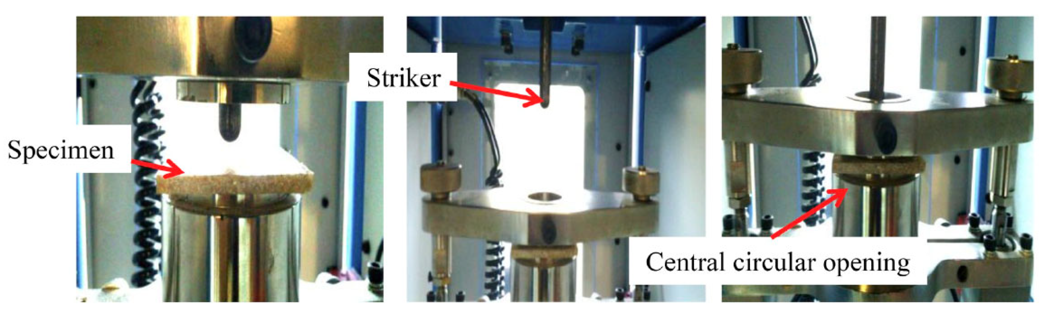
2.3. Experimental Procedure
3. Results and Discussion
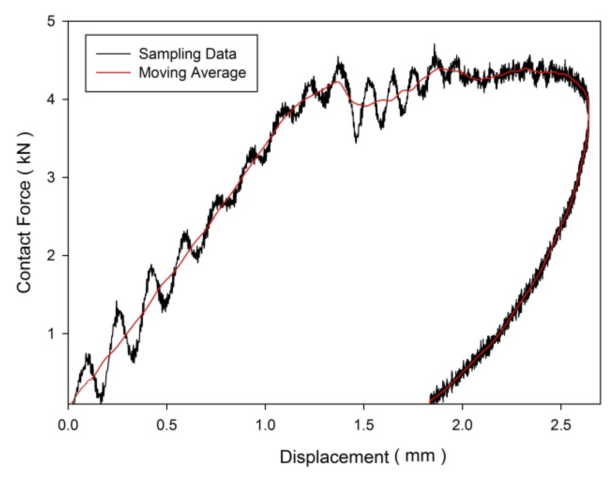
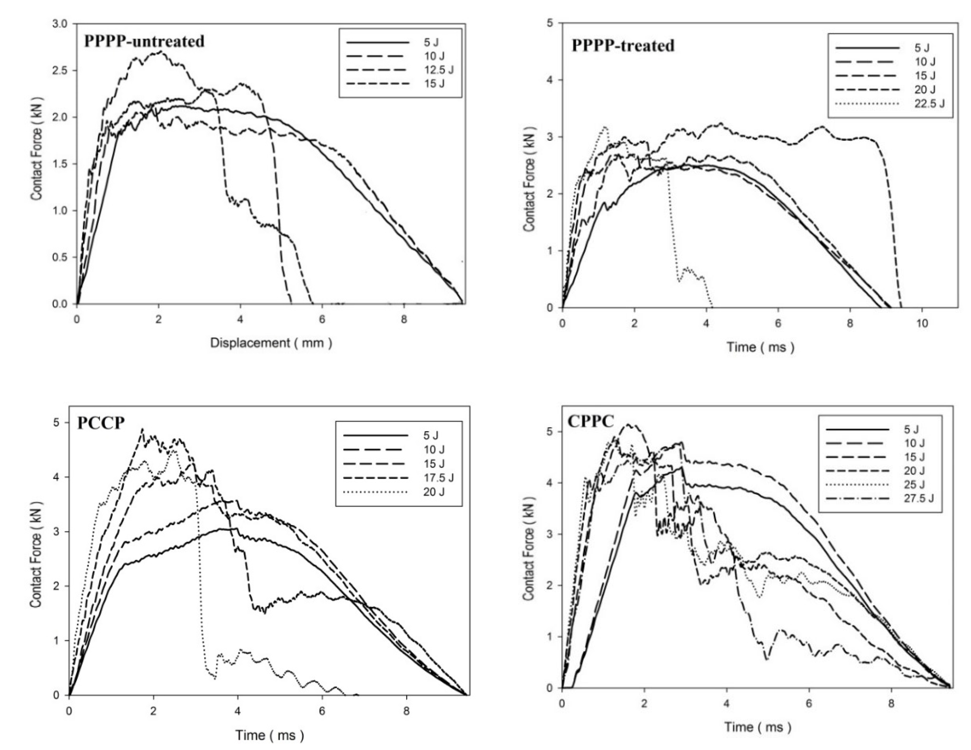
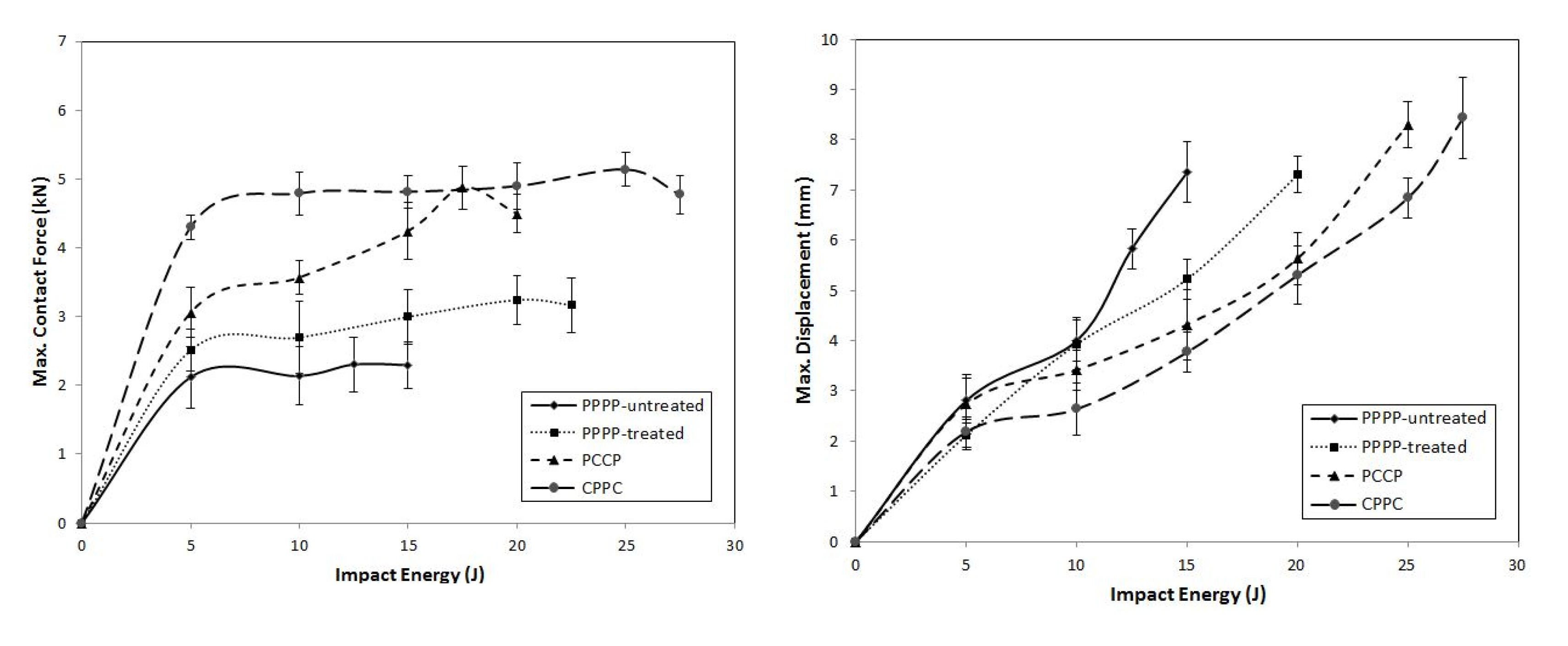
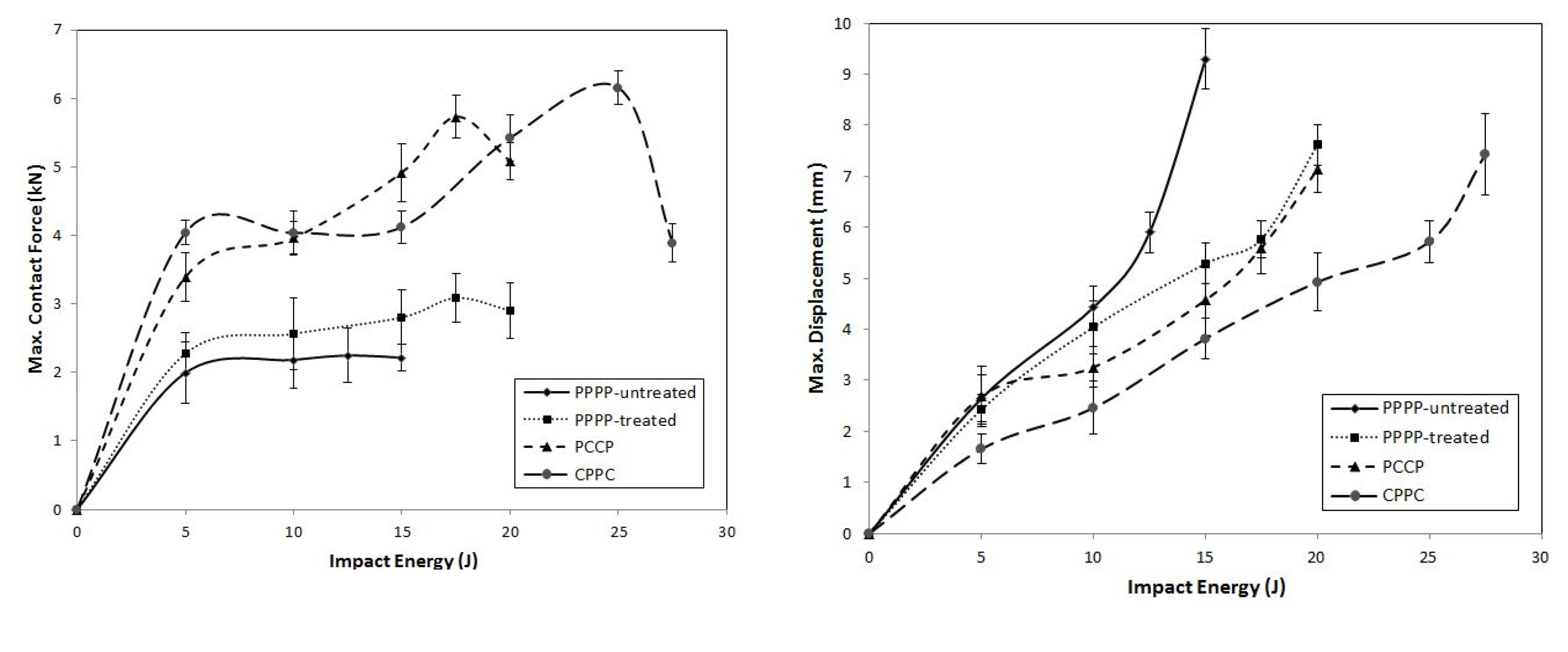
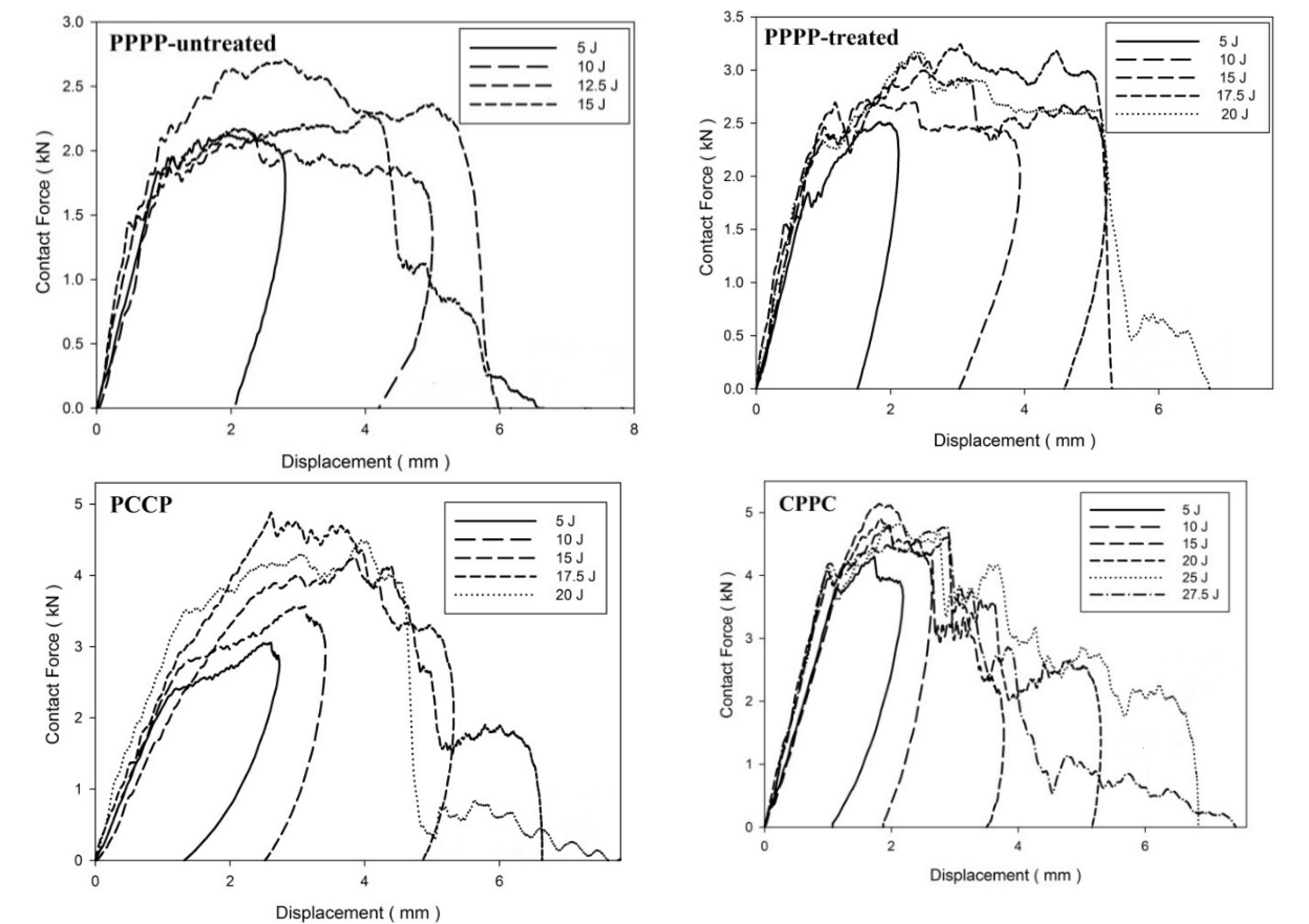
3.1. Impact Behavior
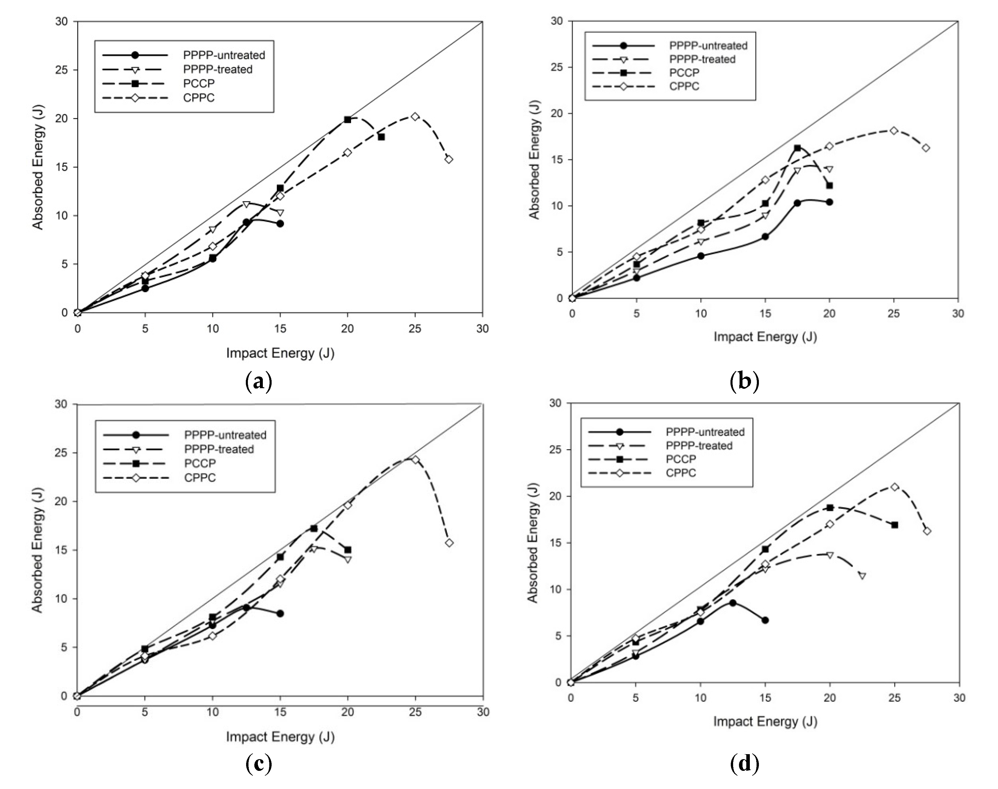
3.2. Impact Energy Profile
3.3. Impact Fracture Morphology
4. Conclusions
- By assigning a carbon ply as the exterior layer, the laminate could withstand more impact energy levels. This was most likely due to the excellent mechanical characteristics of carbon that improve the fracture propagation resistance of the laminates;
- A significant improvement in the maximum contact force was observed when the exterior layer was oriented at ±45°. The shearing effect on the interior and exterior layers was determined to be responsible for this phenomenon;
- Laminates with varying stacking sequences had a lower energy transfer rate and ruptured when subjected to a higher load. The interlinear interface between laminates with various ply orientations is mechanically weak due to mismatches in the bending deformations of the neighbouring plies;
- The laminates with ply orientations of [0°/90°] and [±45°]8 exhibited better energy absorption than those with ply orientations of [±45°2, 0°/90°2]s and [0°/90°2, ±45°2]s. This situation is further explained by the fact that the energy in a composite laminate can readily transfer from one ply to the next if both have the same stacking sequence. Laminates with different stacking sequences have a lower energy transfer rate and rupture when subjected to a higher load;
- PPPP-treated laminates exhibited better impact strength than PPPP-untreated laminates. The elimination of hemicellulose, lignin, waxes, and other contaminants in pure PALF improved the fibre–matrix interaction and increased the impact strength;
- Delamination occurs at the interfaces of differently oriented PALF and carbon layers, and the prevalent type of damage in such buildings is local separation from one another during impact. The crack propagation was substantially slower in laminates with exterior carbon layers than in laminates with PALF exterior layers.
Author Contributions
Funding
Institutional Review Board Statement
Informed Consent Statement
Data availability statement
Acknowledgments
Conflicts of Interest
References
- Flynn, J.; Amiri, A.; Ulven, C. Hybridized carbon and flax fiber composites for tailored performance. Mater. Des. 2016, 102, 21–29. [Google Scholar] [CrossRef]
- Thwe, M.M.; Liao, K. Durability of bamboo-glass fiber reinforced polymer matrix hybrid composites. Compos. Sci. Technol. 2003, 63, 375–387. [Google Scholar] [CrossRef]
- Fu, S.Y.; Xu, G.; Mai, Y.W. On the elastic modulus of hybrid particle/short-fiber/polymer composites. Compos. Part B Eng. 2002, 33, 291–299. [Google Scholar] [CrossRef]
- Anand Raj, M.K.; Muthusamy, S.; Panchal, H.; Mahmoud Ibrahim, A.M.; Alsoufi, M.S.; Elsheikh, A.H. Investigation of mechanical properties of dual-fiber reinforcement in polymer composite. J. Mater. Res. Technol. 2022, 18, 3908–3915. [Google Scholar] [CrossRef]
- Thangaraj, M.; Ahmadein, M.; Alsaleh, N.A.; Elsheikh, A.H. Optimization of Abrasive Water Jet Machining of SiC Reinforced Aluminum Alloy Based Metal Matrix Composites Using Taguchi-DEAR Technique. Materials 2021, 14, 6250. [Google Scholar] [CrossRef]
- Showaib, E.A.; Elsheikh, A.H. Effect of surface preparation on the strength of vibration welded butt joint made from PBT composite. Polym. Test 2020, 83, 106319. [Google Scholar] [CrossRef]
- Elsheikh, A. Bistable Morphing Composites for Energy-Harvesting Applications. Polymers 2022, 14, 1893. [Google Scholar] [CrossRef]
- Joshi, S.V.; Drzal, L.T.; Mohanty, A.K.; Arora, S. Are natural fiber composites environmentally superior to glass fiber reinforced composites? Compos. Part A Appl. Sci. Manuf. 2004, 35, 371–376. [Google Scholar] [CrossRef]
- Assarar, M.; Zouari, W.; Sabhi, H.; Ayad, R.; Berthelot, J.-M. Evaluation of the damping of hybrid carbon–flax reinforced composites. Compos. Struct. 2015, 132, 148–154. [Google Scholar] [CrossRef]
- Jawaid, M.; Abdul Khalil, H.P.S. Cellulosic/synthetic fibre reinforced polymer hybrid composites: A review. Carbohydr. Polym. 2011, 86, 1–18. [Google Scholar] [CrossRef]
- Chollakup, R.; Tantatherdtam, R.; Ujjin, S.; Sriroth, K. Pineapple leaf fiber reinforced thermoplastic composites: Effects of fiber length and fiber content on their characteristics. J. Appl. Polym. Sci. 2011, 119, 1952–1960. [Google Scholar] [CrossRef]
- Najeeb, M.I.; Hameed Sultan, M.T.; Md Shah, A.U.; Muhammad Amir, S.M.; Safri, S.N.A.; Jawaid, M.; Shari, M. Low-Velocity Impact Analysis of Pineapple Leaf Fiber (PALF) Hybrid Composites. Polymers 2021, 13, 3194. [Google Scholar] [CrossRef] [PubMed]
- Asim, M.; Jawaid, M.; Abdan, K.; Ishak, M.R. Effect of Alkali and Silane Treatments on Mechanical and Fibre-matrix Bond Strength of Kenaf and Pineapple Leaf Fibres. J. Bionic. Eng. 2016, 13, 426–435. [Google Scholar] [CrossRef]
- Ibrahim, H.; Farag, M.; Megahed, H.; Mehanny, S. Characteristics of starch-based biodegradable composites reinforced with date palm and flax fibers. Carbohydr. Polym. 2014, 101, 11–19. [Google Scholar] [CrossRef] [PubMed]
- Mishra, S.; Misra, M.; Tripathy, S.S.; Nayak, S.K.; Mohanty, A.K. Potentiality of Pineapple Leaf Fibre as Reinforcement in PALF-Polyester Composite: Surface Modification and Mechanical Performance. J. Reinf. Plast. Compos. 2001, 20, 321–334. [Google Scholar] [CrossRef]
- Pavithran, C.; Mukherjee, P.S.; Brahmakumar, M.; Damodaran, A.D. Impact properties of natural fibre composites. J. Mater. Sci. Lett. 1987, 6, 882–884. [Google Scholar] [CrossRef]
- George, J.; Bhagawan, S.S.; Prabhakaran, N.; Thomas, S. Short pineapple-leaf-fiber-reinforced low-density polyethylene composites. J. Appl. Polym. Sci. 1995, 57, 843–854. [Google Scholar] [CrossRef]
- George, J.; Joseph, K.; Bhagawan, S.S.; Thomas, S. Influence of short pineapple fiber on the viscoelastic properties of low-density polyethylene. Mater. Lett. 1993, 18, 163–170. [Google Scholar] [CrossRef]
- Wisittanawat, U.; Thanawan, S.; Amornsakchai, T. Mechanical properties of highly aligned short pineapple leaf fiber reinforced—Nitrile rubber composite: Effect of fiber content and Bonding Agent. Polym. Test 2014, 35, 20–27. [Google Scholar] [CrossRef]
- Luo, S.; Netravali, A.N. Interfacial and mechanical properties of environment-friendly “green” composites made from pineapple fibers and poly(hydroxybutyrate-co-valerate) resin. J. Mater. Sci. 1999, 34, 3709–3719. [Google Scholar] [CrossRef]
- Liu, W.; Misra, M.; Askeland, P.; Drzal, L.T.; Mohanty, A.K. ‘Green’ composites from soy based plastic and pineapple leaf fiber: Fabrication and properties evaluation. Polymer 2005, 46, 2710–2721. [Google Scholar] [CrossRef]
- Khan, S.H.; Khan, A.A.; Husain, A. Effect of fibre orientation on damage resistance of composite laminates. Int. J. Crashworthiness 2021, 26, 270–282. [Google Scholar] [CrossRef]
- Belingardi, G.; Vadori, R. Low velocity impact tests of laminate glass-fiber-epoxy matrix composite material plates. Int. J. Impact. Eng. 2002, 27, 213–229. [Google Scholar] [CrossRef]
- Sikarwar, R.S.; Velmurugan, R.; Gupta, N.K. Influence of fiber orientation and thickness on the response of glass/epoxy composites subjected to impact loading. Compos. Part B Eng. 2014, 60, 627–636. [Google Scholar] [CrossRef]
- Quaresimin, M.; Ricotta, M.; Martello, L.; Mian, S. Energy absorption in composite laminates under impact loading. Compos. Part B Eng. 2013, 44, 133–140. [Google Scholar] [CrossRef]
- Sayer, M.; Bektaş, N.B.; Sayman, O.; Topçu, M. An Experimental Investigation on the Impact Behaviour of Glass/Epoxy and Hybrid Composite Plates. Adv. Compos. Lett. 2009, 18, 096369350901800401. [Google Scholar] [CrossRef]
- Sarasini, F.; Tirillò, J.; D’Altilia, S.; Valente, T.; Santulli, C.; Touchard, F.; Chocinski-Arnaultc, L.; Mellierc, D.; Lampanid, L.; Gaudenzid, P. Damage tolerance of carbon/flax hybrid composites subjected to low velocity impact. Compos. Part B Eng. 2016, 91, 144–153. [Google Scholar] [CrossRef]
- Aktaş, A.; Aktaş, M.; Turan, F. The effect of stacking sequence on the impact and post-impact behavior of woven/knit fabric glass/epoxy hybrid composites. Compos. Struct. 2013, 103, 119–135. [Google Scholar] [CrossRef]
- Selver, E.; Dalfi, H.; Yousaf, Z. Investigation of the impact and post-impact behaviour of glass and glass/natural fibre hybrid composites made with various stacking sequences: Experimental and theoretical analysis. J. Ind. Text. 2020, 51, 1264–1294. [Google Scholar] [CrossRef]
- Jayabal, S.; Natarajan, U.; Sathiyamurthy, S. Effect of glass hybridization and staking sequence on mechanical behaviour of interply coir–glass hybrid laminate. Bull. Mater. Sci. 2011, 34, 293–298. [Google Scholar] [CrossRef] [Green Version]
- Jothibasu, S.; Mohanamurugan, S.; Vijay, R.; Singaravelu, D.L.; Vinod, A.; Sanjay, M.R. Investigation on the mechanical behavior of areca sheath fibers/jute fibers/glass fabrics reinforced hybrid composite for light weight applications. J. Ind. Text. 2020, 49, 1036–1060. [Google Scholar] [CrossRef]
- Reddy, E.V.S.; Rajulu, A.V.; Reddy, K.H.; Reddy, G.R. Chemical Resistance and Tensile Properties of Glass and Bamboo Fibers Reinforced Polyester Hybrid Composites. J. Reinf. Plast. Compos. 2010, 29, 2119–2123. [Google Scholar] [CrossRef]
- Glória, G.O.; Teles, M.C.A.; Lopes, F.P.D.; Vieira, C.M.F.; Margem, F.M.; de Almeida Gomes, M.; Monteiro, S.N. Tensile strength of polyester composites reinforced with PALF. J. Mater. Res. Technol. 2017, 6, 401–405. [Google Scholar] [CrossRef]
- Mohamed, A.R.; Sapuan, S.M.; Shahjahan, M.; Khalina, A. Effects of Simple Abrasive Combing and Pretreatments on the Properties of Pineapple Leaf Fibers (Palf) and Palf-Vinyl Ester Composite Adhesion. Polym. Plast. Technol. Eng. 2010, 49, 972–978. [Google Scholar] [CrossRef]
- Zin, M.H.; Abdan, K.; Mazlan, N.; Zainudin, E.S.; Liew, K.E. The effects of alkali treatment on the mechanical and chemical properties of pineapple leaf fibres (PALF) and adhesion to epoxy resin. IOP Conf. Ser. Mater. Sci. Eng. 2018, 368, 012035. [Google Scholar] [CrossRef]
- Nopparut, A.; Amornsakchai, T. In fl uence of pineapple leaf fiber and it’s surface treatment on molecular orientation in, and mechanical properties of injection molded nylon composites. Polym. Test 2016, 52, 141–149. [Google Scholar] [CrossRef]
- Rahmanian, S.; Suraya, A.R.; Shazed, M.A.; Zahari, R.; Zainudin, E.S. Mechanical characterization of epoxy composite with multiscale reinforcements: Carbon nanotubes and short carbon fibers. Mater. Des. 2014, 60, 34–40. [Google Scholar] [CrossRef]
- Jeon, Y.-P.; Alway-Cooper, R.; Morales, M.; Ogale, A.A. Chapter 2.8—Carbon Fibers. In Handbook of Advanced Ceramics, 2nd ed; Somiya, S., Ed.; Oxford Academic Press: San Diego, CA, USA, 2013; pp. 143–154. [Google Scholar] [CrossRef]
- Gaba, E.W.; Asimeng, B.O.; Kaufmann, E.E.; Katu, S.K.; Foster, E.J.; Tiburu, E.K. Mechanical and Structural Characterization of Pineapple Leaf Fiber. Fibers 2021, 9, 51. [Google Scholar] [CrossRef]
- Vieille, B.; Pujols-Gonzalez, J.-D.; Bouvet, C.; Breteau, T.; Gautrelet, C. Influence of impact velocity on impact behaviour of hybrid woven-fibers reinforced PEEK thermoplastic laminates. Compos. Part C Open Access 2020, 2, 100029. [Google Scholar] [CrossRef]
- Aktaş, A.; Aktaş, M.; Turan, F. Impact and post impact (CAI) behavior of stitched woven–knit hybrid composites. Compos. Struct. 2014, 116, 243–253. [Google Scholar] [CrossRef]
- He, W.; Xie, D.; Liu, J. Effect of structural parameters on low-velocity impact behavior of aluminum honeycomb sandwich structures with CFRP face sheets. Thin-Walled Struct. 2019, 137, 411–432. [Google Scholar] [CrossRef]
- Hashim, M.K.R.; Abdul Majid, M.S.; Jamir, M.R.M.; Kasim, F.H.; Sultan, M.T.H. The Effect of Stacking Sequence and Ply Orientation on the Mechanical Properties of Pineapple Leaf Fibre (PALF)/Carbon Hybrid Laminate Composites. Polymers 2021, 13, 455. [Google Scholar] [CrossRef] [PubMed]
- Lifshitz, J.M. Impact Strength of Angle Ply Fiber Reinforced Materials. J. Compos. Mater. 1976, 10, 92–101. [Google Scholar] [CrossRef]
- Fotouhi, M.; Jalalvand, M.; Wisnom, M.R. High performance quasi-isotropic thin-ply carbon/glass hybrid composites with pseudo-ductile behaviour in all fibre orientations. Compos. Sci. Technol. 2017, 152, 101–110. [Google Scholar] [CrossRef]
- Cao, Y.; Cai, Y.; Zhao, Z.; Liu, P.; Han, L.; Zhang, C. Predicting the tensile and compressive failure behavior of angle-ply spread tow woven composites. Compos. Struct. 2020, 234, 111701. [Google Scholar] [CrossRef]
- Ridzuan, M.J.M.; Abdul Majid, M.S.; Khasri, A.; Basaruddin, K.S.; Gibson, A.G. Effect of moisture exposure and elevated temperatures on impact response of Pennisetum purpureum/glass-reinforced epoxy (PGRE) hybrid composites. Compos. Part B Eng. 2019, 160, 84–93. [Google Scholar] [CrossRef]
- Sood, M.; Dwivedi, G. Effect of fiber treatment on flexural properties of natural fiber reinforced composites: A review. Egypt. J. Pet. 2018, 27, 775–783. [Google Scholar] [CrossRef]
- Wang, C.; Liu, S.; Ye, Z. Mechanical, hygrothermal ageing and moisture absorption properties of bamboo fibers reinforced with polypropylene composites. J. Reinf. Plast. Compos. 2016, 35, 1062–1074. [Google Scholar] [CrossRef]
- Owen, M.; Ogunleye, C.; Achukwu, E.O. Mechanical Properties of Sisal Fibre-Reinforced Epoxy Composites-Effect of Alkali Concentrations. Adv. Polym. Sci. Technol. 2015, 5, 26–31. [Google Scholar]
- Varna, J.; Joffe, R.; Akshantala, N.V.; Talreja, R. Damage in composite laminates with off-axis plies. Compos. Sci. Technol. 1999, 59, 2139–2147. [Google Scholar] [CrossRef]
- Mujika, F. On the effect of shear and local deformation in three-point bending tests. Polym. Test 2007, 26, 869–877. [Google Scholar] [CrossRef]
- Caminero, M.A.; Rodríguez, G.P.; Muñoz, V. Effect of stacking sequence on Charpy impact and flexural damage behavior of composite laminates. Compos. Struct. 2016, 136, 345–357. [Google Scholar] [CrossRef]
- Caminero, M.A.; García-Moreno, I.; Rodríguez, G.P. Damage resistance of carbon fibre reinforced epoxy laminates subjected to low velocity impact: Effects of laminate thickness and ply-stacking sequence. Polym. Test 2017, 63, 530–541. [Google Scholar] [CrossRef]
- Zhang, Y.; Yan, L.; Zhang, C.; Guo, S. Low-velocity impact response of tube-reinforced honeycomb sandwich structure. Thin-Walled Struct. 2021, 158, 107188. [Google Scholar] [CrossRef]
- Ramakrishnan, K.R.; Corn, S.; Le Moigne, N.; Ienny, P.; Slangen, P. Experimental assessment of low velocity impact damage in flax fabrics reinforced biocomposites by coupled high-speed imaging and DIC analysis. Compos. Part A Appl. Sci. Manuf. 2021, 140, 106137. [Google Scholar] [CrossRef]
- Park, R.; Jang, J. Impact behavior of aramid fiber/glass fiber hybrid composites: The effect of stacking sequence. Polym. Compos. 2001, 22, 80–89. [Google Scholar] [CrossRef]
- Giasin, K.; Dhakal, H.N.; Featheroson, C.A.; Pimenov, D.Y.; Lupton, C.; Jiang, C.; Barouni, A.; Koklu, U. Effect of Fibre Orientation on Impact Damage Resistance of S2/FM94 Glass Fibre Composites for Aerospace Applications: An Experimental Evaluation and Numerical Validation. Polymers 2022, 14, 95. [Google Scholar] [CrossRef]
- Giasin, K. Machining Fibre Metal Laminates and Al2024-T3 Aluminium Alloy; University of Sheffield: Sheffiel, UK, 2017. [Google Scholar]
- Giasin, K.; Ayvar-Soberanis, S. Microstructural investigation of drilling induced damage in fibre metal laminates constituents. Compos. Part A Appl. Sci. Manuf. 2017, 97, 166–178. [Google Scholar] [CrossRef]
- Evci, C. Thickness-dependent energy dissipation characteristics of laminated composites subjected to low velocity impact. Compos. Struct. 2015, 133, 508–521. [Google Scholar] [CrossRef]
- Romasko, B.W. Flat Composite Panel Impact Testing and Characterization by Ultrasonic Non-Destructive Evaluation; University of California: San Diego, CA, USA, 2022. [Google Scholar]
- Hart-Smith, L.J. A New Approach to Fibrous Composite Laminate Strength Prediction; NASA: Washington, DC, USA, 1990.
- Majid, M.A.; Daud, R.; Afendi, M.; Amin, N.A.M.; Cheng, E.M.; Gibson, A.G.; Hekman, M. Stress-strain response modelling of glass fibre reinforced epoxy composite pipes under multiaxial loadings. J. Mech. Eng. Sci. 2014, 6, 916–928. [Google Scholar] [CrossRef]
- Sezgin, H.; Berkalp, O.B. The effect of hybridization on significant characteristics of jute/glass and jute/carbon-reinforced composites. J. Ind. Text. 2017, 47, 283–296. [Google Scholar] [CrossRef]
- Pinto, F.; Boccarusso, L.; De Fazio, D.; Cuomo, S.; Durante, M.; Meo, M. Carbon/hemp bio-hybrid composites: Effects of the stacking sequence on flexural, damping and impact properties. Compos. Struct. 2020, 242, 112148. [Google Scholar] [CrossRef]
- De Morais, W.A.; Monteiro, S.N.; D’Almeida, J.R.M. Evaluation of repeated low energy impact damage in carbon–epoxy composite materials. Compos. Struct. 2005, 67, 307–315. [Google Scholar] [CrossRef]
- Razali, N.; Sultan, M.T.H.; Mustapha, F.; Yidris, N.; Ishak, M.R. Impact Damage on Composite Structures—A Review. Int. J. Eng. Sci. 2014, 3, 8–20. [Google Scholar]
- Drzal, L.T.; Madhukar, M. Fibre-matrix adhesion and its relationship to composite mechanical properties. J. Mater. Sci. 1993, 28, 569–610. [Google Scholar] [CrossRef]
- Ogin, S.L.; Brøndsted, P.; Zangenberg, J. 1—Composite Materials: Constituents, Architecture, and Generic Damage. In Modeling Damage, Fatigue and Failure of Composite Materials; Talreja, R., Varna, J., Eds.; Woodhead Publishing: Cambridge, UK, 2016; pp. 3–23. [Google Scholar] [CrossRef]
- Oh, H.-T.; Won, J.-I.; Woo, S.-C.; Kim, T.-W. Determination of Impact Damage in CFRP via PVDF Signal Analysis with Support Vector Machine. Materials 2020, 13, 5207. [Google Scholar] [CrossRef]
- Sádaba, S.; Martínez-Hergueta, F.; Lopes, C.S.; Gonzalez, C. LLorca J. 10—Virtual Testing of Impact in Fiber Reinforced Laminates. In Structural Integrity and Durability of Advanced Composites; Beaumont, P.W.R., Soutis, C., Hodzic, A., Eds.; Woodhead Publishing: Cambridge, UK, 2015; pp. 247–270. [Google Scholar] [CrossRef]
- Børvik, T.; Hopperstad, O.S.; Berstad, T.; Langseth, M. Perforation of 12mm thick steel plates by 20mm diameter projectiles with flat, hemispherical and conical noses: Part II: Numerical simulations. Int. J. Impact. Eng. 2002, 27, 37–64. [Google Scholar] [CrossRef]
- Panettieri, E.; Fanteria, D.; Danzi, F. Delaminations growth in compression after impact test simulations: Influence of cohesive elements parameters on numerical results. Compos. Struct. 2016, 137, 140–147. [Google Scholar] [CrossRef]
- Murat, B.I.S.; Rahman, A.A.A. Study of Impact Damage Behavior in Woven Carbon Fiber Plates. Procedia Eng. 2017, 170, 47–54. [Google Scholar] [CrossRef]
- Lee, B.; Walsh, T.; Won, S.; Patts, H.; Song, J.; Mayer, A.H. Penetration Failure Mechanisms of Armor-Grade Fiber Composites under Impact. J. Compos. Mater. 2001, 35, 1605–1633. [Google Scholar] [CrossRef]


| Property | Epoxy | Fibre | |
|---|---|---|---|
| Carbon Fibre | PALF | ||
| Tensile Strength (MPa) | 55 | 3530 | 630 |
| Tensile Modulus (GPa) | 1.75 | 230 | 10.46 |
| Strain at failure (%) | 6 | 1.5 | 1.05 |
| Reference | [37] | [38] | [39] |
| (a) | ||||||
|---|---|---|---|---|---|---|
| Lamination | Orientation | Layering Pattern | Volume Fraction of Fibre (%) | Thickness (mm) | ||
| PALF | Carbon Fibre | Total | ||||
| Cross-ply symmetric | [0°, 90°]8 | PPPP-untreated | 24 | - | 24 | 5.83 ± 0.35 |
| PPPP-treated | 21 | - | 21 | 5.84 ± 0.20 | ||
| PCCP | 16.7 | 6.2 | 22.9 | 5.52 ± 0.11 | ||
| CPPC | 16.7 | 6.2 | 22.9 | 5.44 ± 0.15 | ||
| Angle-ply symmetric | [±45°]8 | PPPP-untreated | 24 | - | 24 | 5.91 ± 0.22 |
| PPPP-treated | 21 | - | 21 | 5.73 ± 0.24 | ||
| PCCP | 16.7 | 6.2 | 22.9 | 5.55 ± 0.16 | ||
| CPPC | 16.7 | 6.2 | 22.9 | 5.48 ± 0.12 | ||
| Symmetric Quasi-isotropic | [±45°2, 0°/90°2]s | PPPP-untreated | 24 | - | 24 | 5.86 ± 0.13 |
| PPPP-treated | 21 | - | 21 | 5.78 ± 0.22 | ||
| PCCP | 16.7 | 6.2 | 22.9 | 5.53 ± 0.16 | ||
| CPPC | 16.7 | 6.2 | 22.9 | 5.43 ± 0.21 | ||
| [0°/90°2, ±45°2]s | PPPP-untreated | 24 | - | 24 | 5.91 ± 0.20 | |
| PPPP-treated | 21 | - | 21 | 5.73 ± 0.18 | ||
| PCCP | 16.7 | 6.2 | 22.9 | 5.60 ± 0.15 | ||
| CPPC | 16.7 | 6.2 | 22.9 | 5.46 ± 0.22 | ||
| (b) | ||||||
| PPPP-Untreated | PPPP-Treated | PCCP | CPPC | |||
| [0°, 90°]8 |  |  |  |  | ||
| [±45°]8 |  | 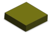 | 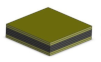 |  | ||
| [±45°2, 0°/90°2]s |  |  |  |  | ||
| [0°/90°2, ±45°2]s |  |  |  |  | ||
| Layering Sequence | Energy Impact (J) | |
|---|---|---|
| [0°, 90°]8 | PPPP-untreated | 5, 10, 12.5, 15 |
| PPPP-treated | 5, 10, 12.5, 15 | |
| PCCP | 5, 10, 15, 20, 22.5 | |
| CPPC | 5, 10, 15, 20, 25, 27.5 | |
| [±45°]8 | PPPP-untreated | 5, 10, 15, 17.5, 20 |
| PPPP-treated | 5, 10, 15, 17.5, 20 | |
| PCCP | 5, 10, 15, 17.5, 20 | |
| CPPC | 5, 10, 15, 20, 25, 27.5 | |
| [±45°2, 0°/90°2]s | PPPP-untreated | 5, 10, 12.5, 15 |
| PPPP-treated | 5, 10, 15, 17.5, 20 | |
| PCCP | 5, 10, 15, 17.5, 20 | |
| CPPC | 5, 10, 15, 20, 25, 27.5 | |
| [0°/90°2, ±45°2]s | PPPP-untreated | 5, 10, 12.5, 15 |
| PPPP-treated | 5, 10, 15, 17.5, 20 | |
| PCCP | 5, 10, 15, 17.5, 20 | |
| CPPC | 5, 10, 15, 20, 25, 27.5 | |
| Impact Level | PPPP-Untreated | PPPP-Treated | ||
|---|---|---|---|---|
| Top-Side | Bottom-Side | Top-Side | Bottom-Side | |
| Indentation (maximum) |  |  |  |  |
| Penetration |  |  |  |  |
| Perforation |  |  |  |  |
| Impact Level | PCCP | CPPC | ||
|---|---|---|---|---|
| Top-Side | Bottom-Side | Top-Side | Bottom-Side | |
| Indentation (maximum) |  |  |  |  |
| Penetration |  |  |  |  |
| Perforation |  |  |  |  |
| Impact Level | [0°/90°2, ±45°2]s | [±45°2, 0°/90°2]s | ||
|---|---|---|---|---|
| Top-Side | Bottom-Side | Top-Side | Bottom-Side | |
| Indentation (maximum) |  |  |  |  |
| Penetration |  |  |  |  |
| Perforation |  |  |  |  |
Publisher’s Note: MDPI stays neutral with regard to jurisdictional claims in published maps and institutional affiliations. |
© 2022 by the authors. Licensee MDPI, Basel, Switzerland. This article is an open access article distributed under the terms and conditions of the Creative Commons Attribution (CC BY) license (https://creativecommons.org/licenses/by/4.0/).
Share and Cite
Hashim, M.K.R.; Abdul Majid, M.S.; Mohd Jamir, M.R.; Kasim, F.H.; Alshahrani, H.A.; Deros, M.A.M.; Hui, D. Effects of Ply Orientations and Stacking Sequences on Impact Response of Pineapple Leaf Fibre (PALF)/Carbon Hybrid Laminate Composites. Materials 2022, 15, 6121. https://doi.org/10.3390/ma15176121
Hashim MKR, Abdul Majid MS, Mohd Jamir MR, Kasim FH, Alshahrani HA, Deros MAM, Hui D. Effects of Ply Orientations and Stacking Sequences on Impact Response of Pineapple Leaf Fibre (PALF)/Carbon Hybrid Laminate Composites. Materials. 2022; 15(17):6121. https://doi.org/10.3390/ma15176121
Chicago/Turabian StyleHashim, Mohd Khairul Rabani, Mohd Shukry Abdul Majid, Mohd Ridzuan Mohd Jamir, Farizul Hafiz Kasim, Hassan A. Alshahrani, Mohd Azaman Md Deros, and David Hui. 2022. "Effects of Ply Orientations and Stacking Sequences on Impact Response of Pineapple Leaf Fibre (PALF)/Carbon Hybrid Laminate Composites" Materials 15, no. 17: 6121. https://doi.org/10.3390/ma15176121
APA StyleHashim, M. K. R., Abdul Majid, M. S., Mohd Jamir, M. R., Kasim, F. H., Alshahrani, H. A., Deros, M. A. M., & Hui, D. (2022). Effects of Ply Orientations and Stacking Sequences on Impact Response of Pineapple Leaf Fibre (PALF)/Carbon Hybrid Laminate Composites. Materials, 15(17), 6121. https://doi.org/10.3390/ma15176121