
Influence of Surfacing Fe-Based Alloy Layers on Wire Arc Additive Manufactured Ni-Based Superalloys Material on Its Microstructure and Wear Properties

Abstract
:1. Introduction
2. Materials and Methods
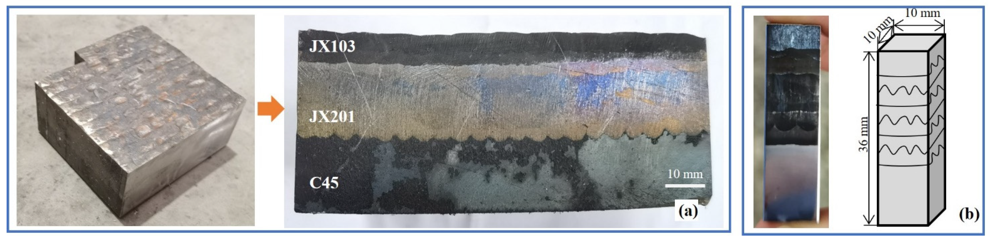
2.1. Materials and Wire Arc Additive Forming
2.2. Microstructural and Properties Analysis
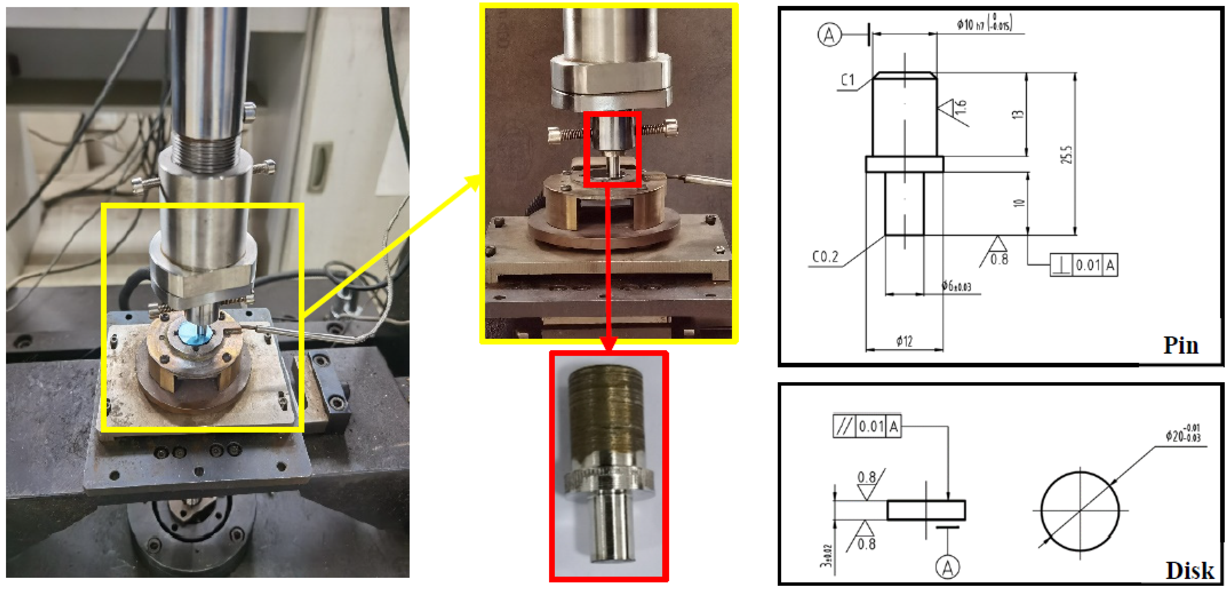
2.3. Sliding Wear Test
3. Results and Discussion
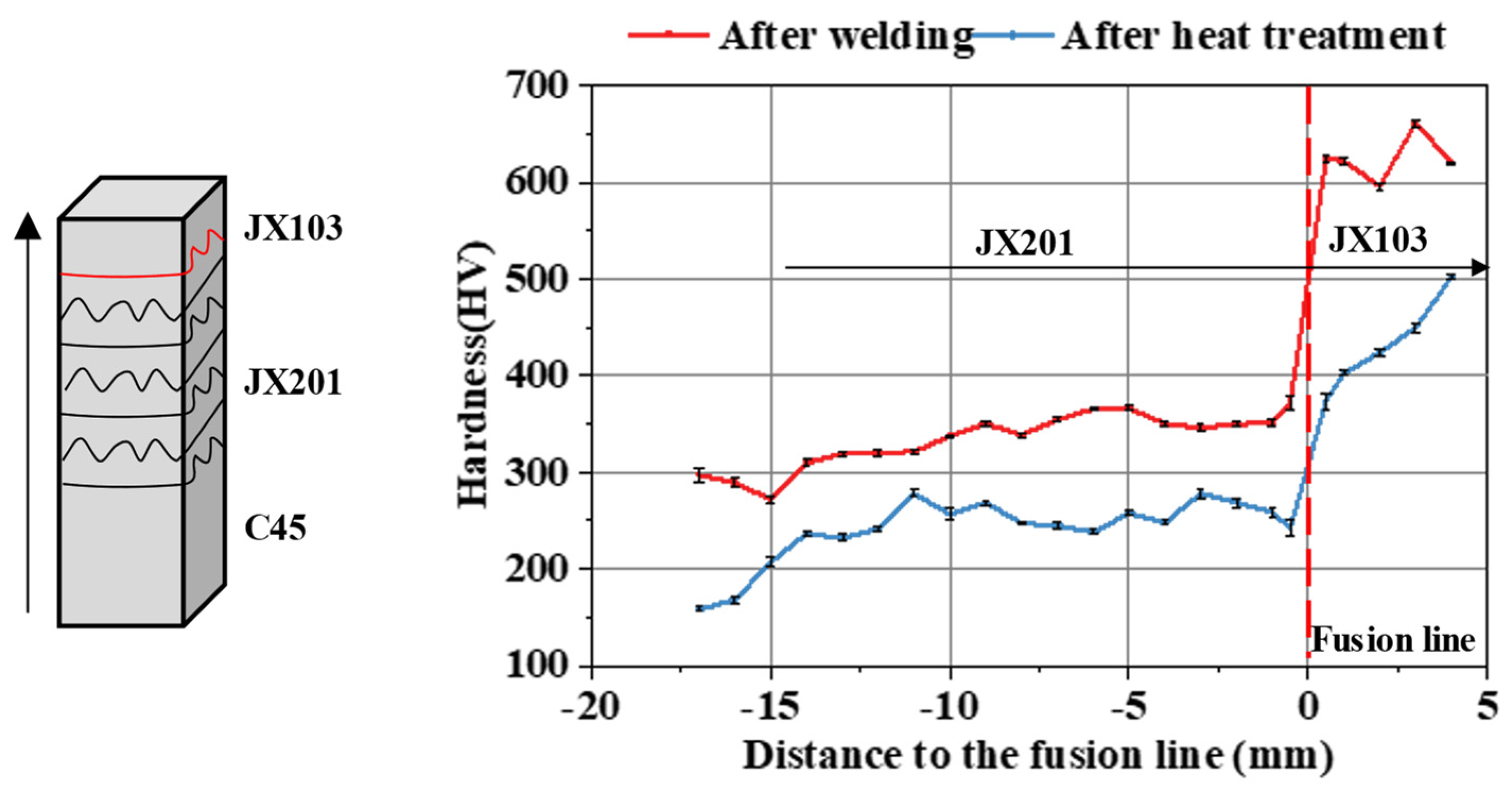
3.1. Microhardness
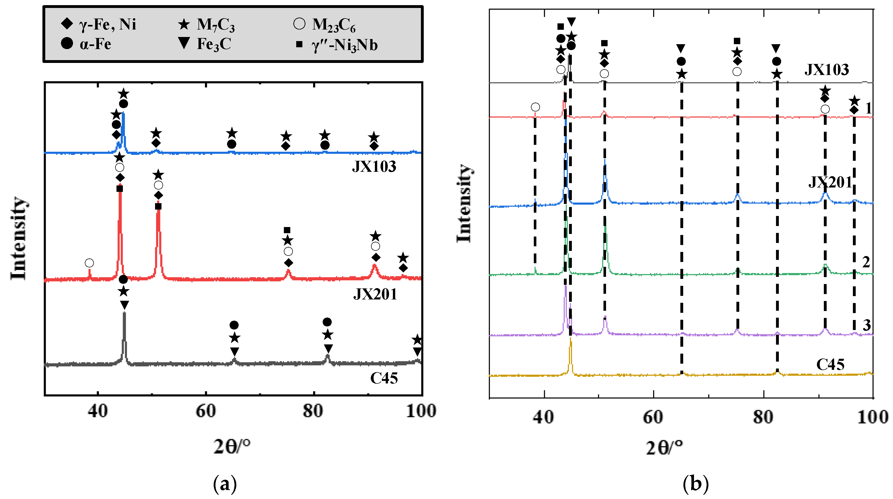
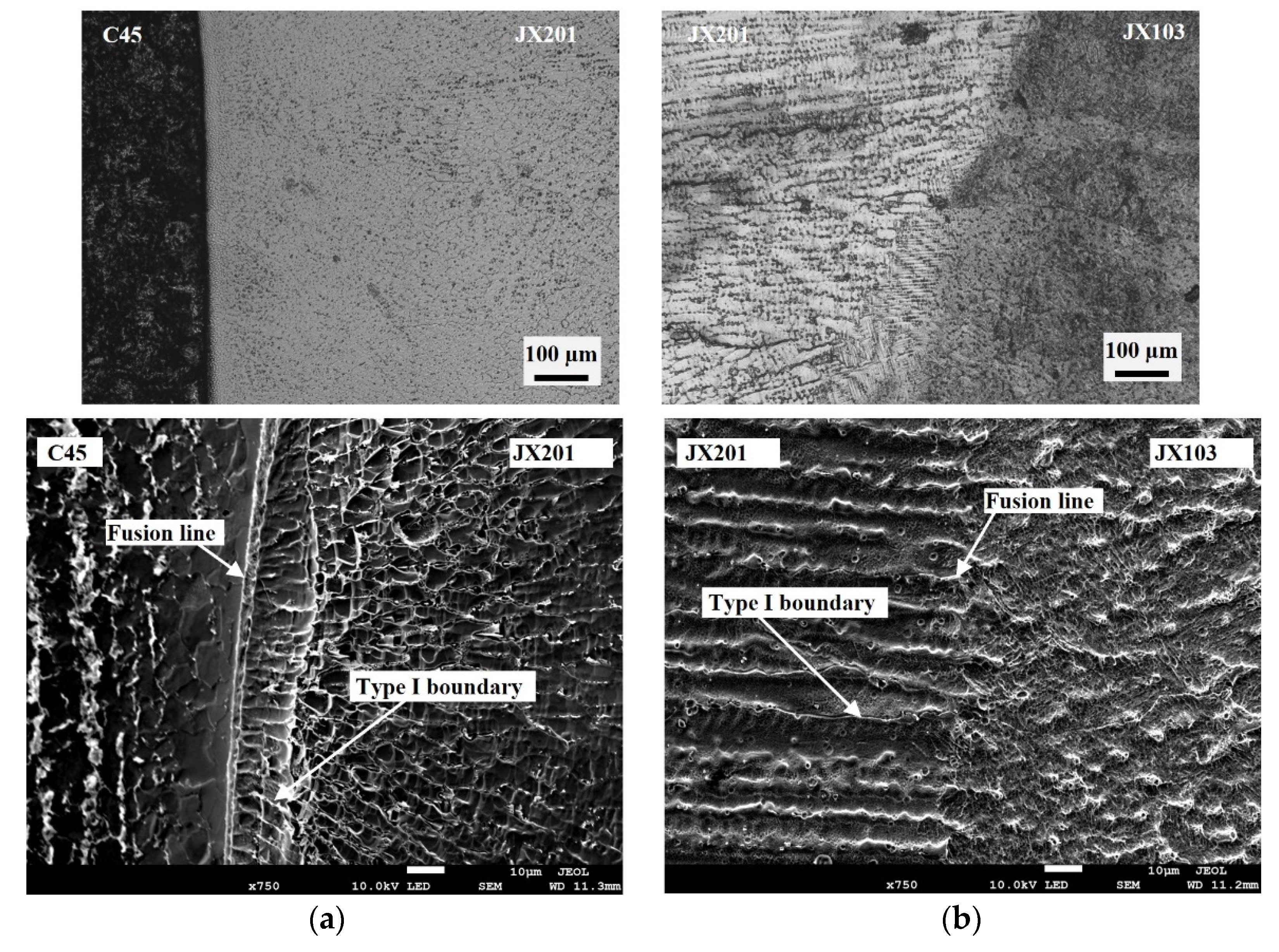
3.2. Microstructure and Phase Characterization
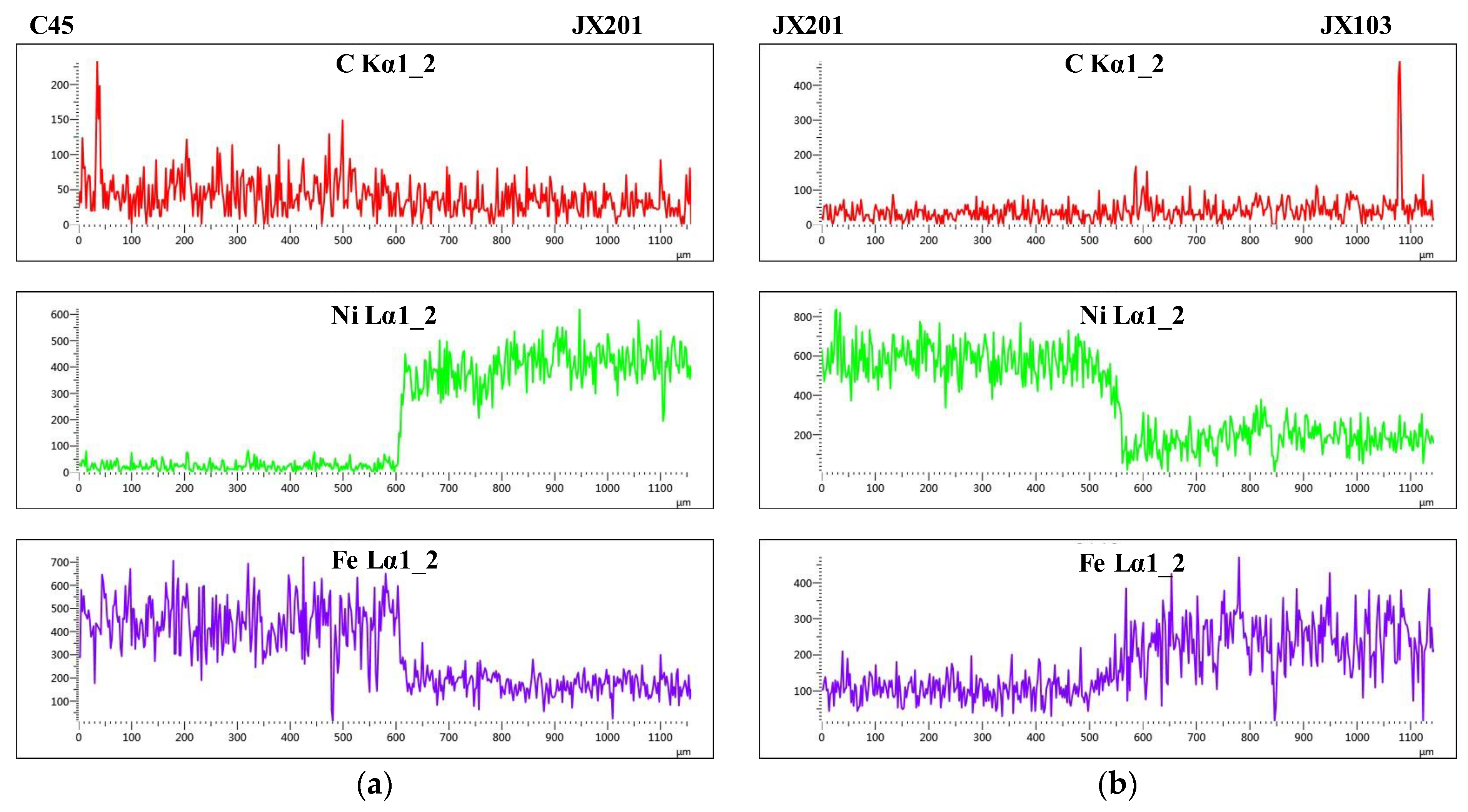
3.3. Dilution
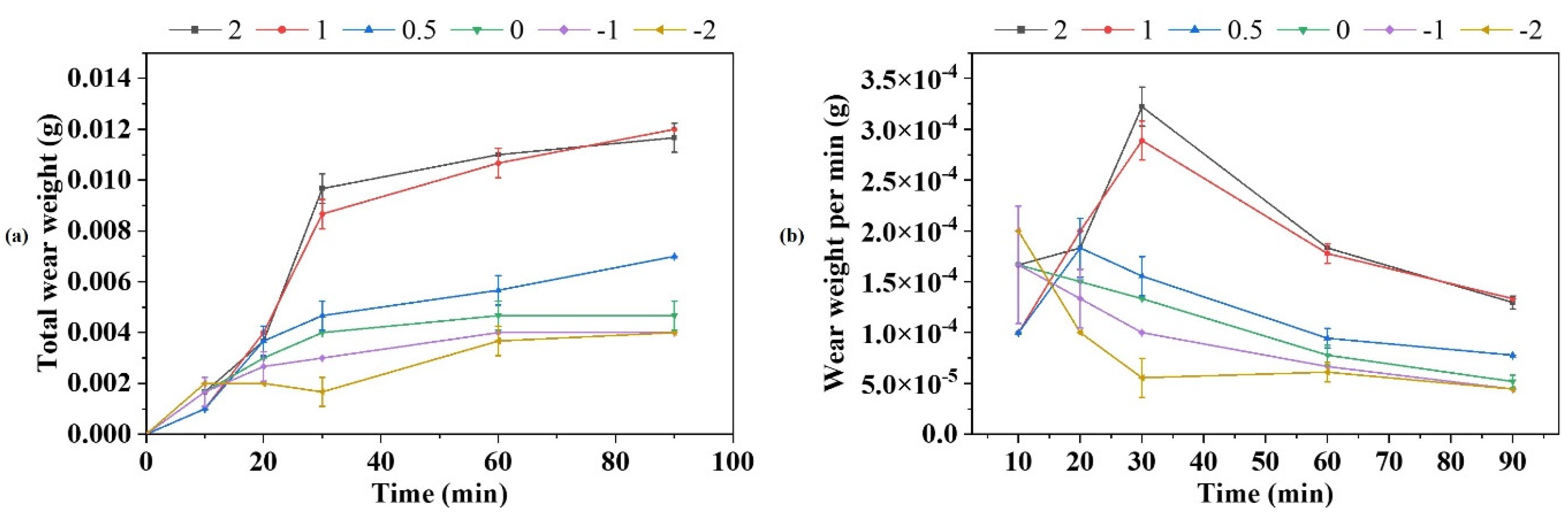
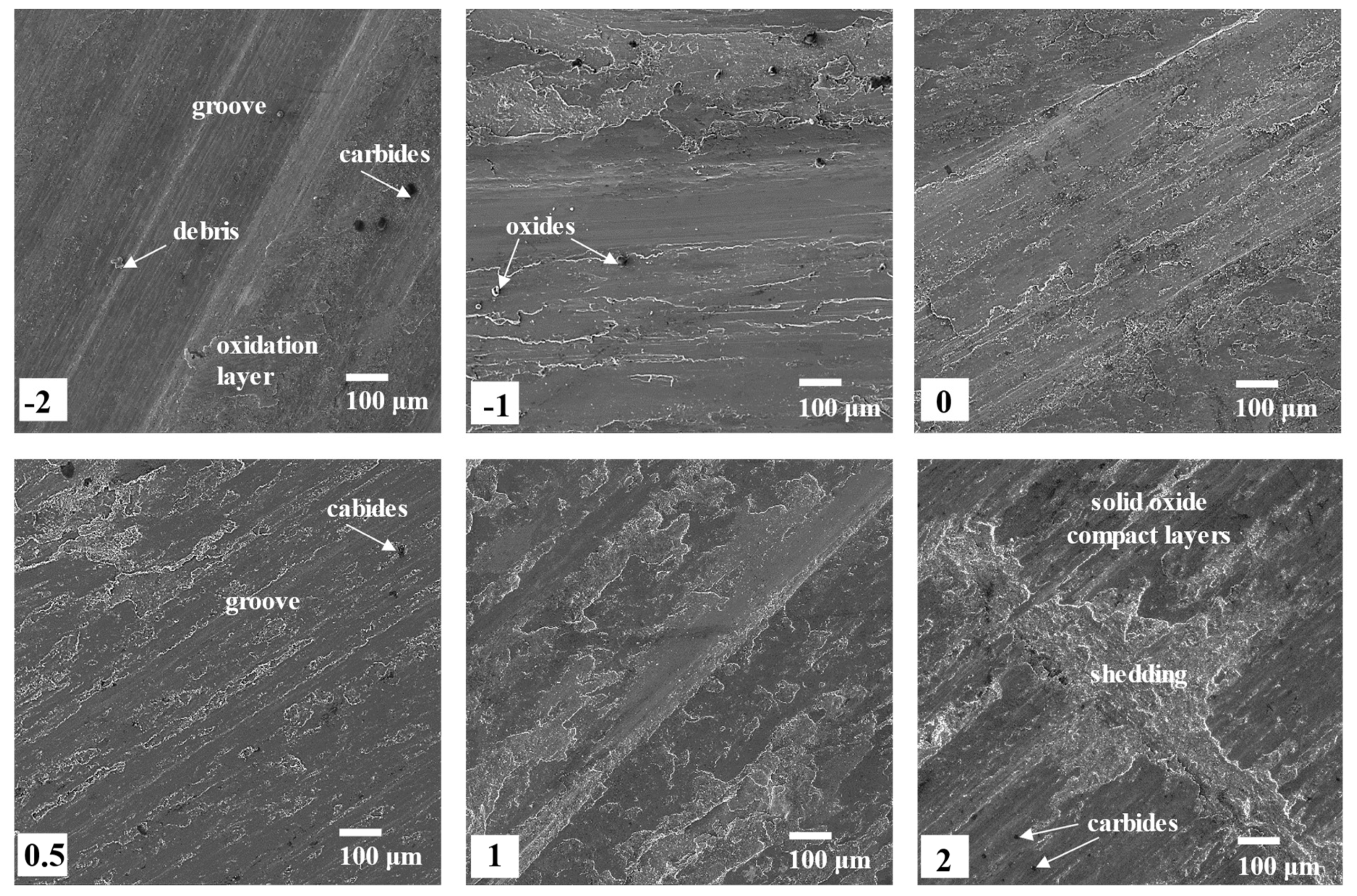
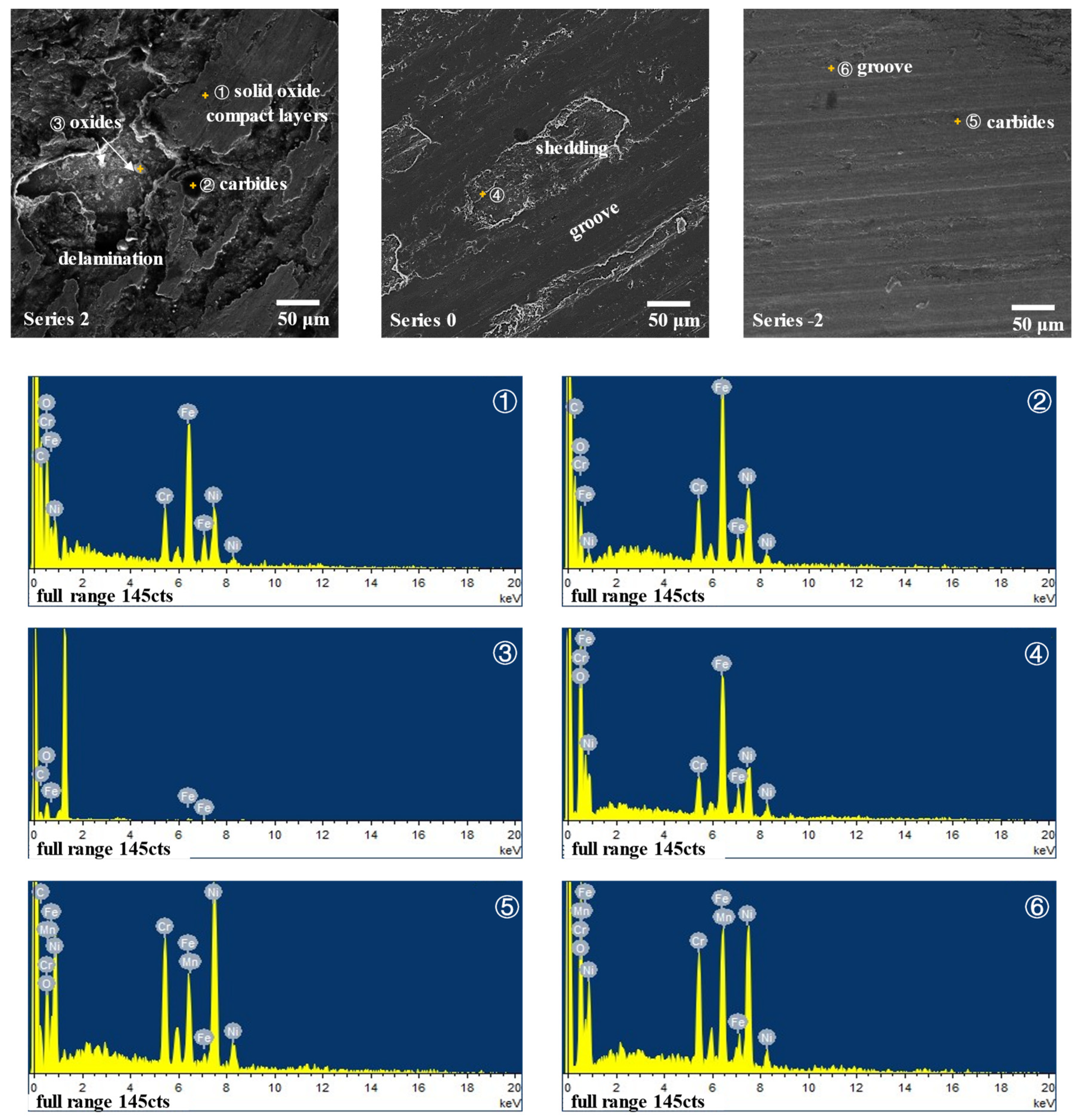
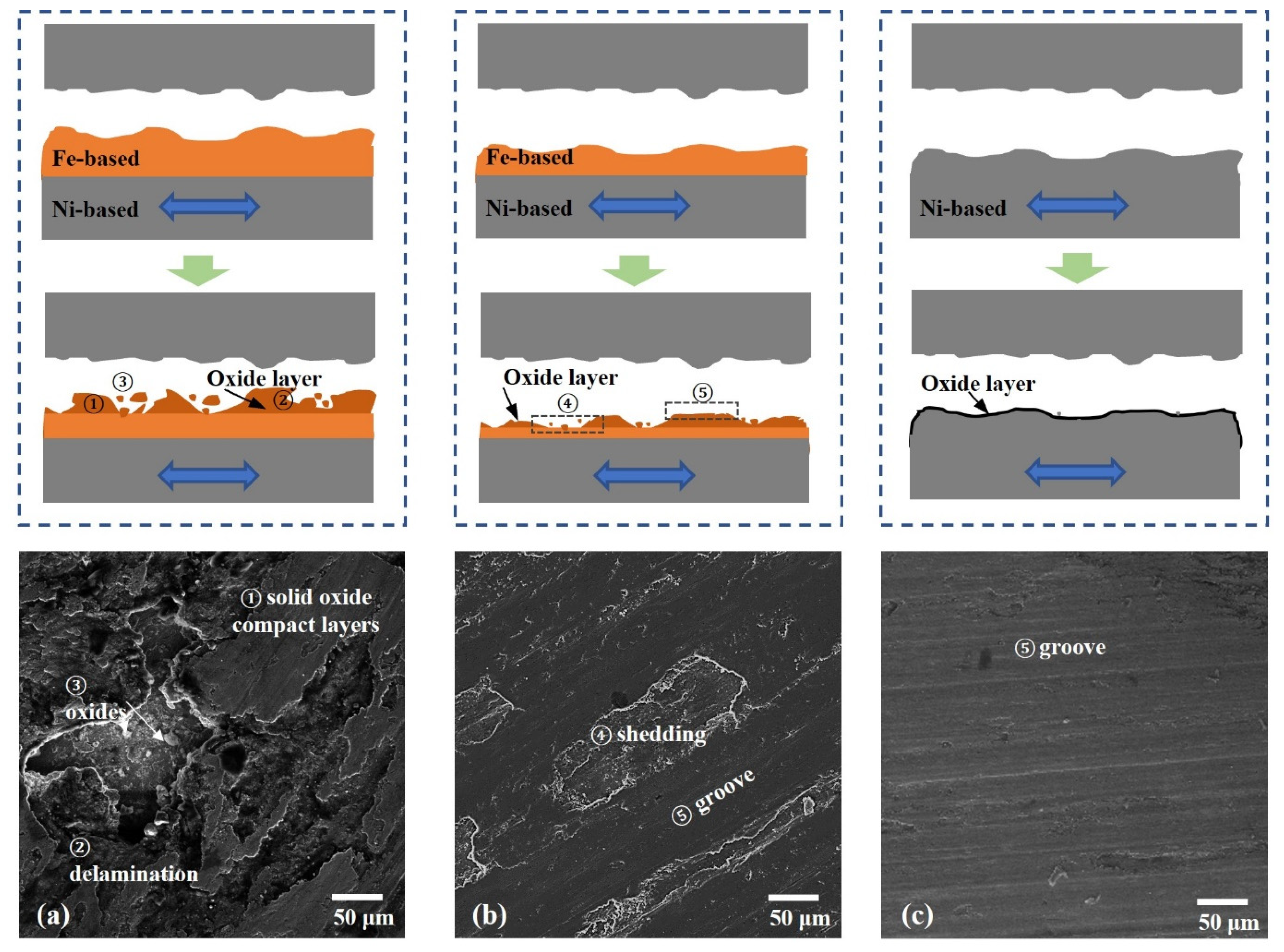
3.4. Wear Behavior
4. Conclusions
- (1)
- By changing the material of the last welded layers from Ni-based superalloy to Fe-based alloy, the mean surface hardness is increased from HV350 to HV400, and a smooth hardness transition was achieved after heat treatment.
- (2)
- The tendency for the disappearance of γ-Fe and the transformation of the carbide form was found in the welded layers. Cellular dendritic growth and type-Ⅰ boundaries were observed in the fusion boundary between these two materials. However, no type-Ⅱ boundary occurred, indicating a good crack resistance of the fusion boundary.
- (3)
- The dilution of the fusion boundary is at a relatively low level (<30%), and no decarburization phenomenon was found.
- (4)
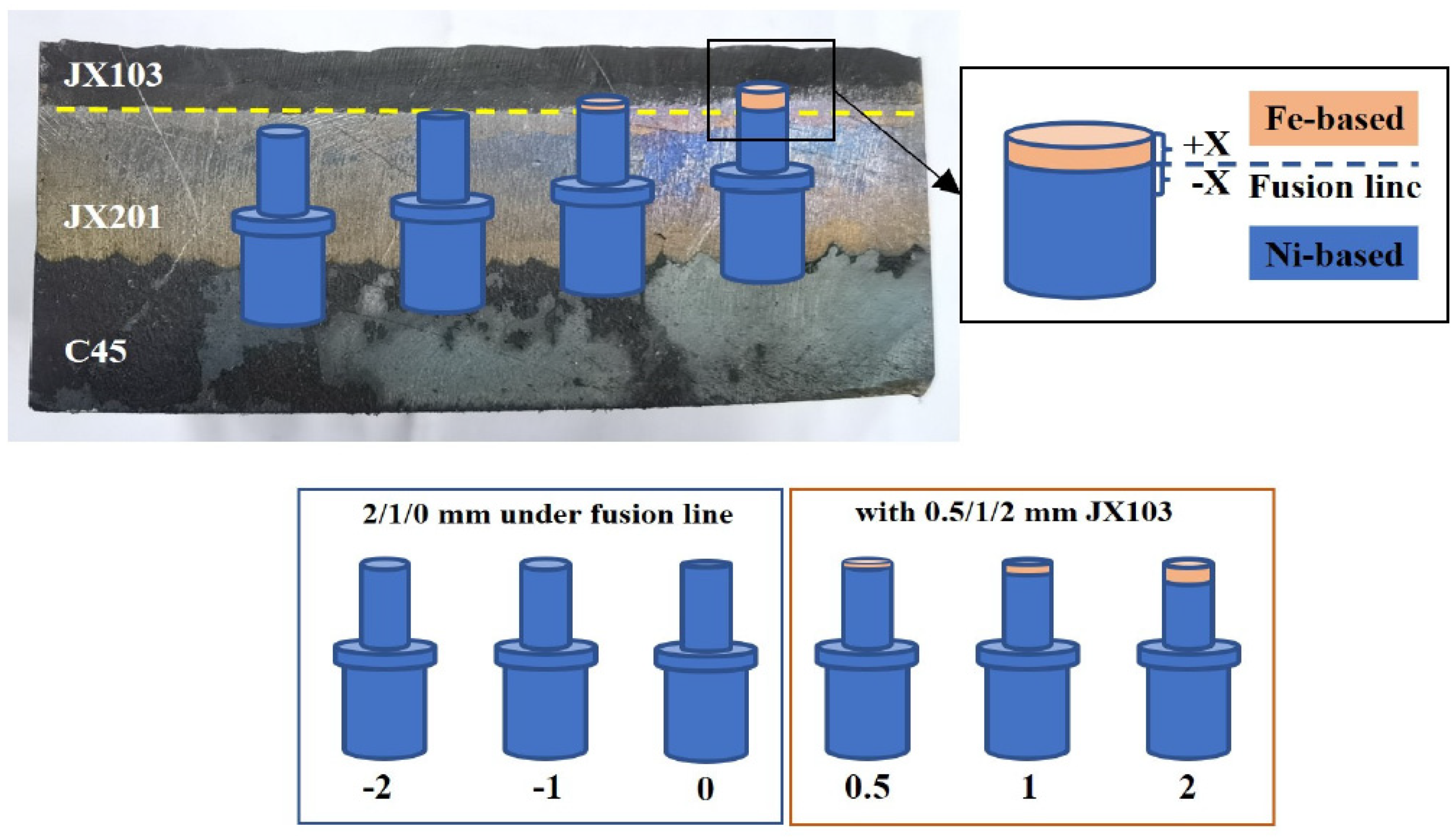
- The wear resistance of JX201 was decreased by changing the last layer to JX103; however, as the residual thickness of JX103 decreased, the influence gradually decreased. Meanwhile, the wear mechanism changed from severe abrasive and adhesive wear to light abrasive wear. When the thickness is less than 0.5 mm, the wear weight per minute is already at the same level as the sample without JX103.
Author Contributions
Funding
Institutional Review Board Statement
Informed Consent Statement
Data Availability Statement
Conflicts of Interest
References
- Bayramoglu, M.; Polat, H. Cost and performance evaluation of different surface treated dies for hot forging process. J. Mater. Process. Technol. 2008, 205, 394–403. [Google Scholar] [CrossRef]
- Hong, X.; Xiao, G.; Zhang, Y. Research on gradient additive remanufacturing of ultra-large hot forging die based on automatic wire arc additive manufacturing technology. Int. J. Adv. Manuf. Technol. 2021, 116, 2243–2254. [Google Scholar] [CrossRef]
- Smolik, J. The influence of thickness of CrN coating on the durability of hot forging dies. Open Eng. 2011, 1, 210–216. [Google Scholar] [CrossRef]
- Emamverdian, A.; Sun, Y. Current failure mechanisms and treatment methods of hot forging tools (dies)—A review. Eng. Fail. Anal. 2021, 129, 105678. [Google Scholar] [CrossRef]
- Shen, L.; Zhou, J. Microstructure and mechanical properties of hot forging die manufactured by bimetal-layer surfacing technology. J. Mater. Process. Technol. 2017, 239, 147–159. [Google Scholar] [CrossRef]
- Shen, L.; Zhou, J. Analysis of service condition of large hot forging die and refabrication of die by bimetal-layer weld surfacing technology with a cobalt-based superalloy and a ferrous alloy. J. Manuf. Process. 2018, 31, 731–743. [Google Scholar] [CrossRef]
- Gao, F.; Zhou, J. Microstructure and properties of surfacing layers of dies manufactured by bimetal-gradient-layer surfacing technology before and after service. Int. J. Adv. Manuf. Technol. 2017, 88, 1289–1297. [Google Scholar] [CrossRef]
- Xia, Y.; Jin, L. A comparative study on the microstructures and mechanical properties between surfacing nickel-based superalloy and surfacing cobalt-based superalloy. Mater. Res. Express 2019, 6, 96589. [Google Scholar] [CrossRef]
- Panagiotis, K.; Preetam, D.; Pedro, A. Fabrication of geometrical features using wire and arc additive manufacture. Proc. Inst. Mech. Eng. Part B J. Eng. Manuf. 2012, 226, 1042–1051. [Google Scholar]
- Hu, Q.; Wang, X.; Shen, X. Microstructure and corrosion resistance in bimetal materials of Q345 and 308 steel wire-arc additive manufacturing. Crystals 2021, 11, 1401. [Google Scholar] [CrossRef]
- Ozsoy, A.; Tureyen, E.B.; Baskan, M. Microstructure and mechanical properties of hybrid additive manufactured dissimilar 17-4 ph and 316l stainless steels. Mater. Today Commun. 2021, 28, 102561. [Google Scholar] [CrossRef]
- Ytab, C.; Jsab, C.; Sha, B. Effects of cold metal transfer mode on the reaction layer of wire and arc additive manufactured Ti-6Al-4V/Al-6.25Cu dissimilar alloys. J. Mater. Sci. Technol. 2020, 74, 35–45. [Google Scholar]
- Ding, D.; Pan, Z.; Cuiuri, D. Wire-feed additive manufacturing of metal components: Technologies, developments and future interests. Int. J. Adv. Manuf. Technol. 2015, 81, 465–481. [Google Scholar] [CrossRef]
- Hao, X.; Dong, H.; Yu, F.; Li, P. Arc welding of titanium alloy to stainless steel with cu foil as interlayer and ni-based alloy as filler metal. J. Mater. Res. Technol. 2021, 13, 48–60. [Google Scholar] [CrossRef]
- Wu, B. Enhanced interface strength in steel-nickel bimetallic component fabricated using wire arc additive manufacturing with interweaving deposition strategy. J. Mater. Sci. Technol. 2020, 52, 226–234. [Google Scholar] [CrossRef]
- Chen, N.; Khan, H.; Wan, Z. Microstructural characteristics and crack formation in additively manufactured bimetal material of 316l stainless steel and Inconel 625. Addit. Manuf. 2020, 32, 101037. [Google Scholar] [CrossRef]
- Dhinakaran, V.; Ajith, J.; Fahmidha, A. Wire Arc Additive Manufacturing (WAAM) process of nickel based superalloys—A review. Mater. Today Proc. 2020, 21, 920–925. [Google Scholar] [CrossRef]
- Liu, D.; Liu, R.; Wei, P. Comparative behaviour of cobalt and iron base hardfacing alloys. Surf. Eng. 2012, 28, 338–344. [Google Scholar] [CrossRef]
- Barrick, E.J.; Jain, D. Effects of Heating and Cooling Rates on Phase Transformations in 10 Wt Pct Ni Steel and Their Application to Gas Tungsten Arc Welding. Met. Mater. Trans. A 2017, 48, 5890–5910. [Google Scholar] [CrossRef]
- Mu, W.; Cai, Y. Microstructure characteristics and properties of fusion boundary in 9%Ni steel joint filled with Ni-based alloy. Mater. Charact. 2020, 165, 110390. [Google Scholar] [CrossRef]
- Cui, T.; Xu, X. Effects of composition and microstructure on oxidation and stress corrosion cracking susceptibility of stainless steel claddings in hydrogenated PWR primary water. J. Nucl. Mater. 2021, 553, 153057. [Google Scholar] [CrossRef]
- Farias, F.W.C.; Da Cruz Payão Filho, J. Microstructural characterization of Ni-based superalloy 625 clad welded on a 9% Ni steel pipe by plasma powder transferred arc. Surf. Coat. Technol. 2019, 374, 1024–1037. [Google Scholar] [CrossRef]
- Rajeev, G.P.; Kamaraj, M.; Bakshi, S.R. Comparison of microstructure, dilution and wear behavior of Stellite 21 hardfacing on H13 steel using cold metal transfer and plasma transferred arc welding processes. Surf. Coat. Technol. 2019, 375, 383–394. [Google Scholar]
- Zhang, Z.; Huang, X. A New Method for Weld Dilution Calculation through Chemical Composition Analysis. Metals 2021, 11, 131. [Google Scholar] [CrossRef]
- Kesavan, D.; Kamaraj, M. The microstructure and high temperature wear performance of a nickel base hardfaced coating. Surf. Coat. Technol. 2010, 204, 4034–4043. [Google Scholar] [CrossRef]
- Arabi Jeshvaghani, R.; Harati, E. Effects of surface alloying on microstructure and wear behavior of ductile iron surface-modified with a nickel-based alloy using shielded metal arc welding. Mater. Des. 2011, 32, 1531–1536. [Google Scholar] [CrossRef]
- Arabi Jeshvaghani, R.; Jaberzadeh, M. Microstructural study and wear behavior of ductile iron surface alloyed by Inconel 617. Mater. Des. 2014, 54, 491–497. [Google Scholar] [CrossRef]
- Shu, F.Y.; Wu, L. Microstructure and high-temperature wear mechanism of laser cladded CoCrBFeNiSi high-entropy alloy amorphous coating. Mater. Lett. 2018, 211, 235–238. [Google Scholar] [CrossRef]


| Material | C | Mn | Cr | Si | Ni | Mo | Al | W | V | P | S | Fe | Nb |
|---|---|---|---|---|---|---|---|---|---|---|---|---|---|
| JX103 | 0.25 | 1.61 | 5.51 | 0.72 | 1.5 | 1.69 | 0.21 | 1.04 | 0.24 | 0.013 | 0.004 | ||
| JX201 | 0.02 | 2.8 | 19.5 | 0.5 | 67 | 2 | 2.5 | ||||||
| C45 | 0.42~0.50 | 0.50~0.80 | ≤0.25 | 0.17~0.37 | ≤0.25 | <0.10 | ≤0.035 | ≤0.035 |
| JX201 to C45 | 7.8 | 8.3 | 92.1 | 93.2 | 92.7 | 8.7 | 13.5 | 2.8 | 2 | 7.36 | ||
| Avg. | 92.7 | Avg. | 8.3 | |||||||||
| JX103 to JX201 | 8.3 | 7.8 | 2.3 | 0 | 2.7 | 55.8 | 71.8 | 68.5 | 87 | 24.15 | ||
| Avg. | 1.67 | Avg. | 65.4 | |||||||||
Publisher’s Note: MDPI stays neutral with regard to jurisdictional claims in published maps and institutional affiliations. |
© 2022 by the authors. Licensee MDPI, Basel, Switzerland. This article is an open access article distributed under the terms and conditions of the Creative Commons Attribution (CC BY) license (https://creativecommons.org/licenses/by/4.0/).
Share and Cite
Yu, Y.; Qu, Z.; Zhang, J.; Zhou, J. Influence of Surfacing Fe-Based Alloy Layers on Wire Arc Additive Manufactured Ni-Based Superalloys Material on Its Microstructure and Wear Properties. Materials 2022, 15, 6020. https://doi.org/10.3390/ma15176020
Yu Y, Qu Z, Zhang J, Zhou J. Influence of Surfacing Fe-Based Alloy Layers on Wire Arc Additive Manufactured Ni-Based Superalloys Material on Its Microstructure and Wear Properties. Materials. 2022; 15(17):6020. https://doi.org/10.3390/ma15176020
Chicago/Turabian StyleYu, Yingyan, Zhiyuan Qu, Jiansheng Zhang, and Jie Zhou. 2022. "Influence of Surfacing Fe-Based Alloy Layers on Wire Arc Additive Manufactured Ni-Based Superalloys Material on Its Microstructure and Wear Properties" Materials 15, no. 17: 6020. https://doi.org/10.3390/ma15176020
APA StyleYu, Y., Qu, Z., Zhang, J., & Zhou, J. (2022). Influence of Surfacing Fe-Based Alloy Layers on Wire Arc Additive Manufactured Ni-Based Superalloys Material on Its Microstructure and Wear Properties. Materials, 15(17), 6020. https://doi.org/10.3390/ma15176020