
Simulation Research on Continuous Concrete Beams Reinforced with External Prestressed CFRP Tendons


Abstract
:1. Introduction
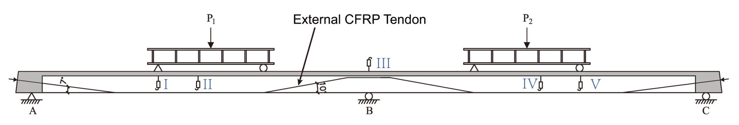
2. Testing Setup
2.1. T-Beam Design
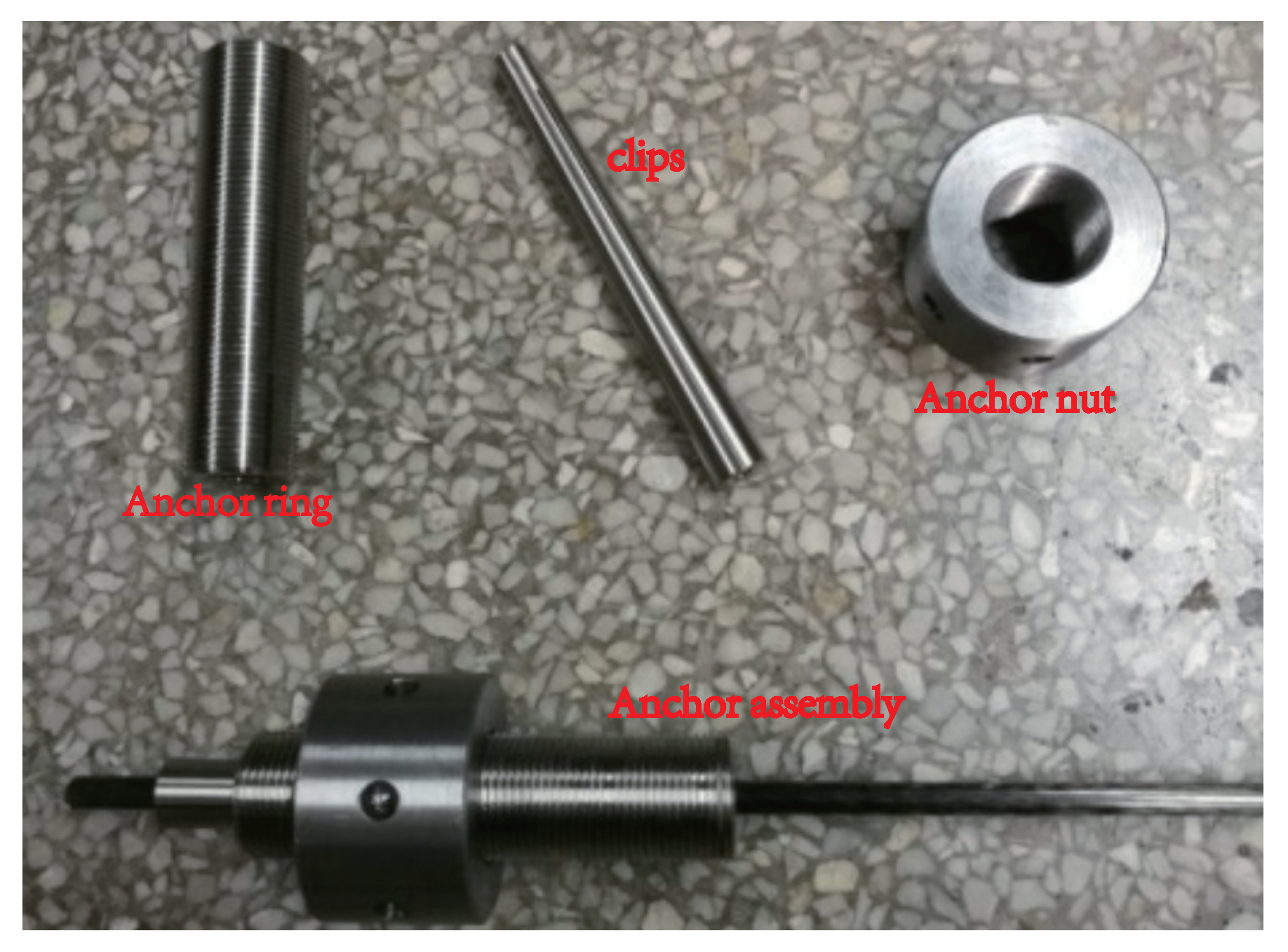
2.2. Materials
2.3. Testing Procedure
3. Test Results and Discussion
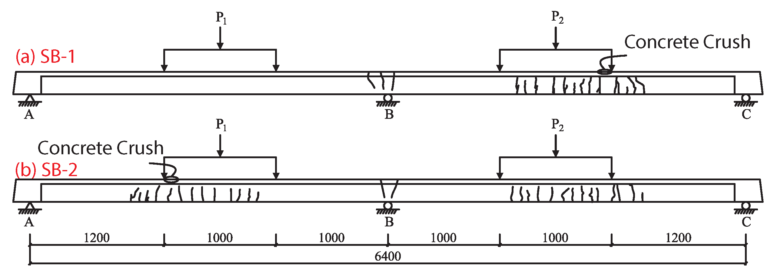
3.1. Failure Type
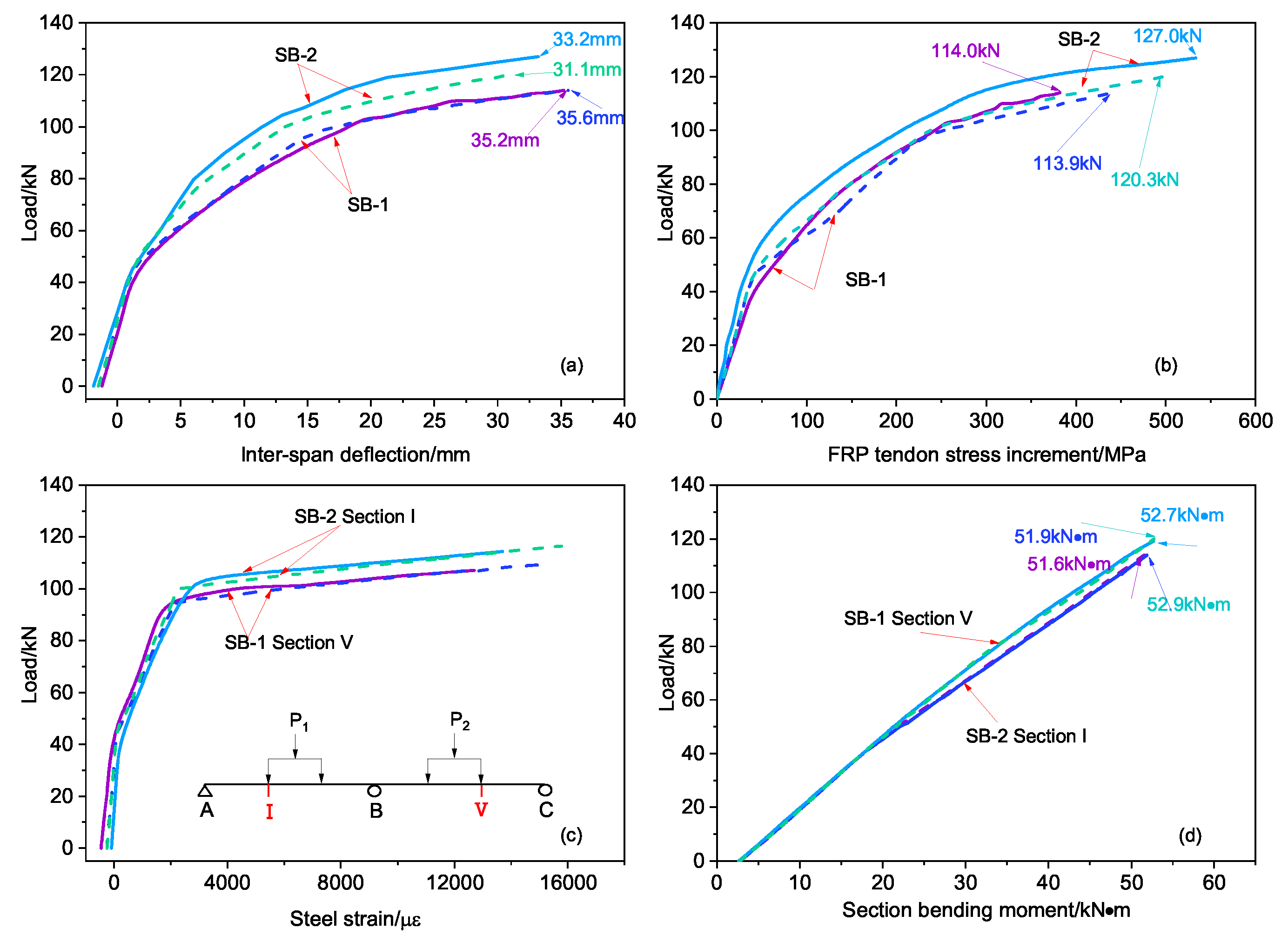
3.2. Load–Displacement Relationship
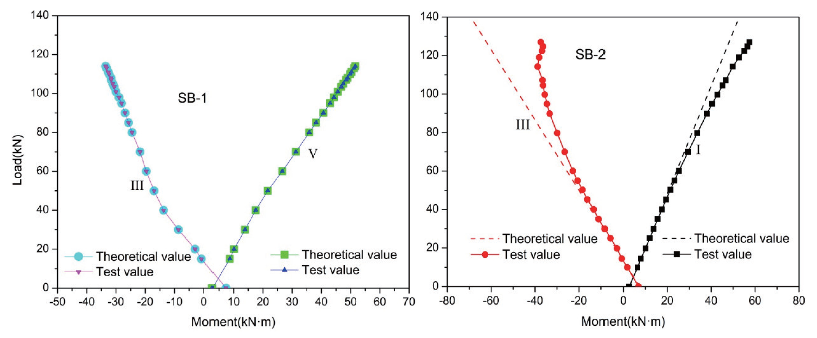
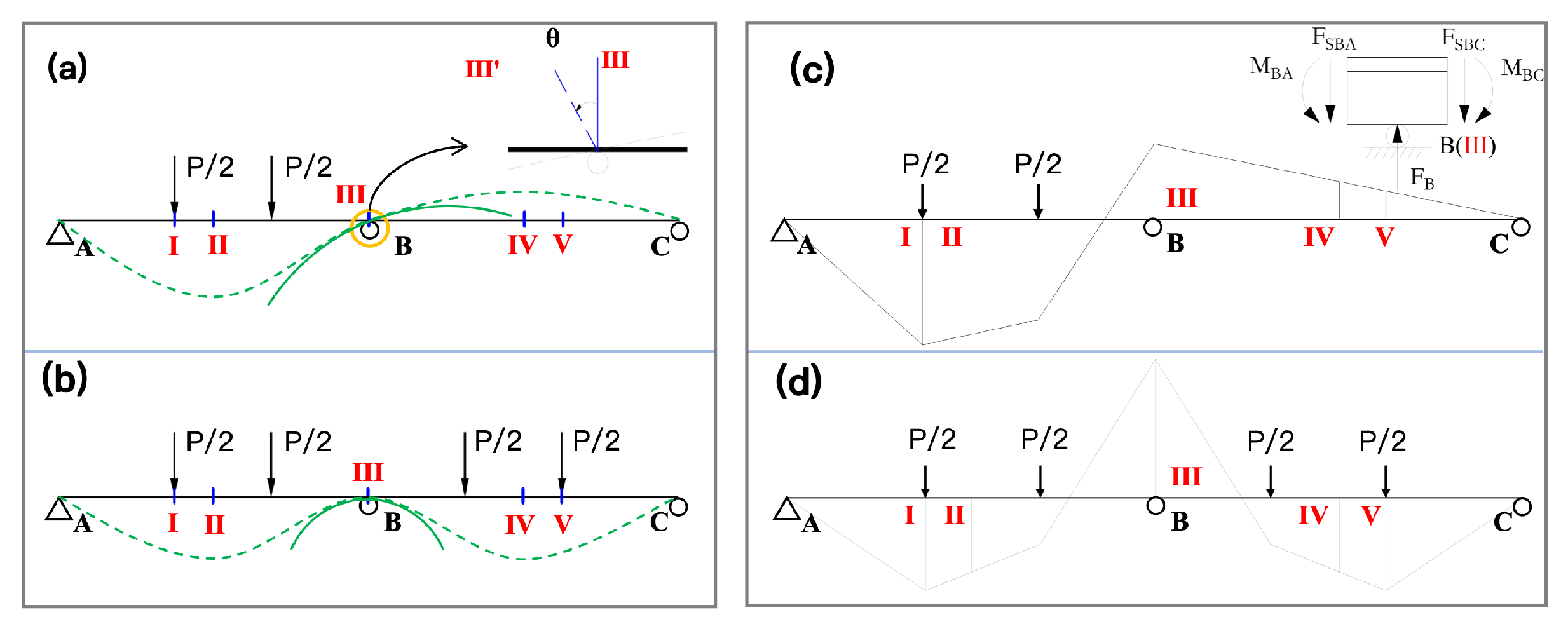
3.3. Moment Redistribution
3.4. Strengthening Mechanism under Symmetrical Loading
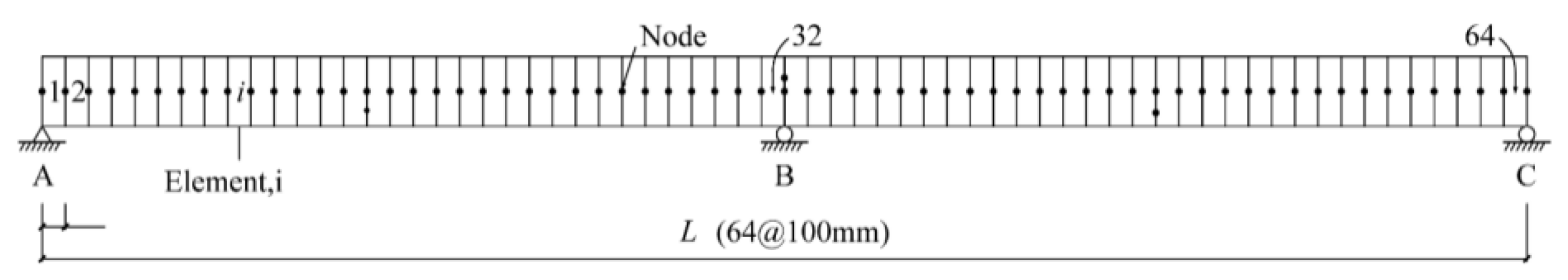
4. Finite Element Simulation Calibration
5. Parametric Study and Results
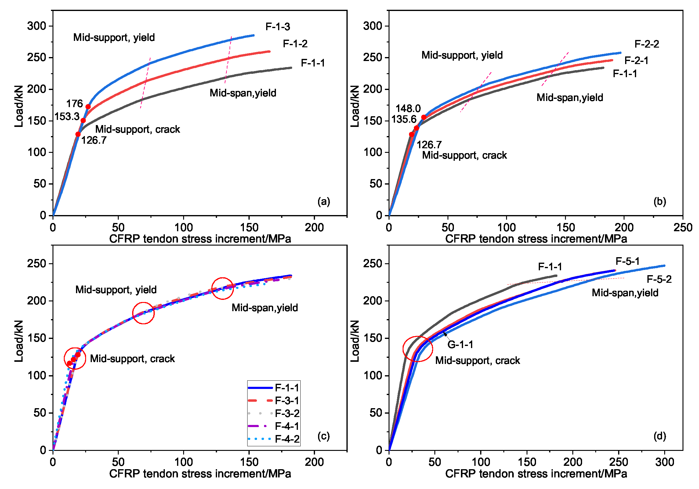
5.1. Stress Increment of External Prestressed Tendons
5.2. Secondary Bending Moments
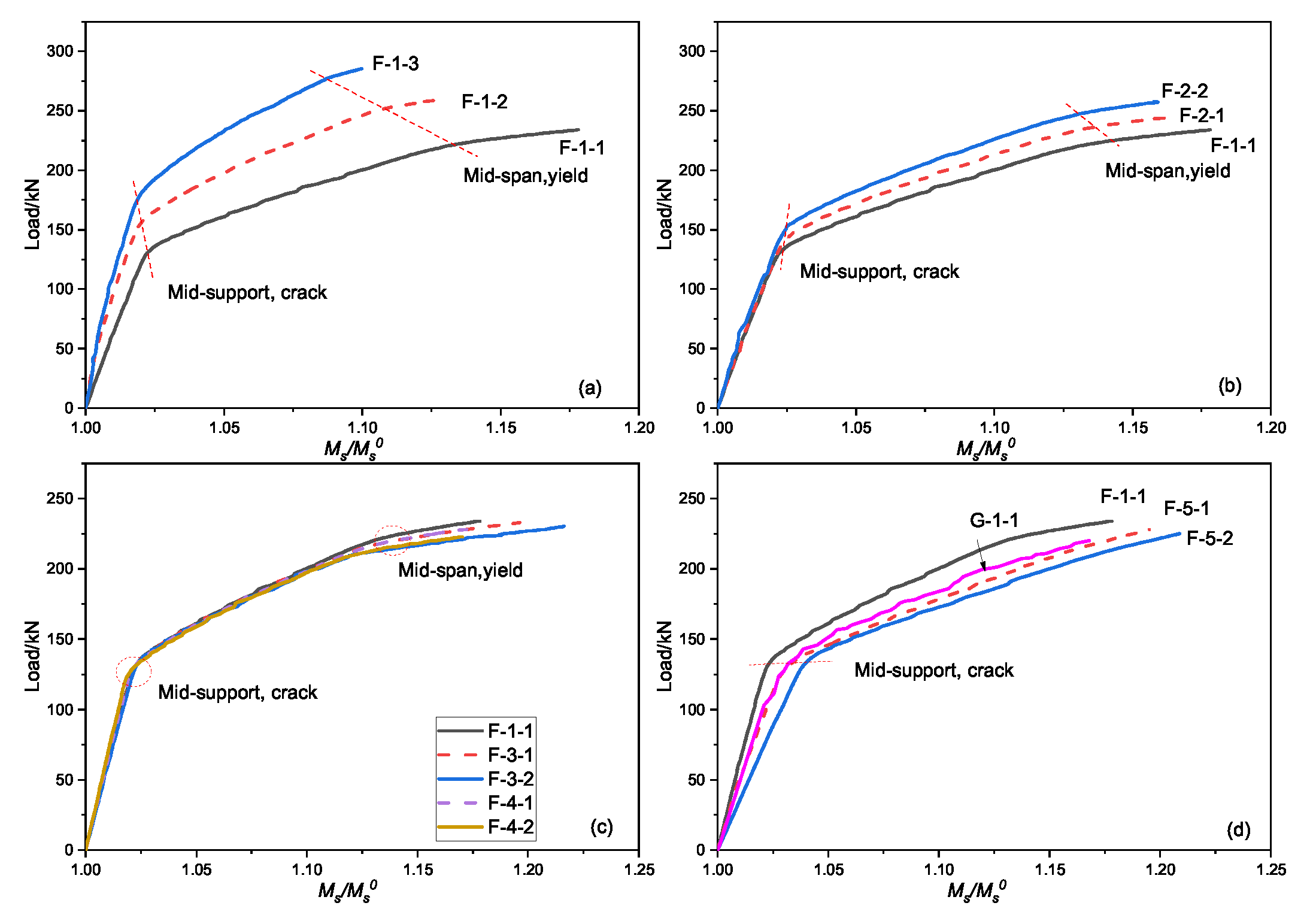
5.3. Bending Moment Redistribution
6. Conclusions
- The final failure modes of continuous beams SB1 and SB2 are both flexural failure. The crushed concrete in the compression zone causes the continuous beam to lose its bearing capacity.
- The external prestressed tendon stress increment displays a three-stage development law as external loading increases. The initial prestress value has the greatest influence on the CFRP prestress increment, followed by the elastic modulus and cross-sectional area of the external prestressed tendon. The cross-sectional area of the reinforcements and the eccentricity of the external prestressed tendon has little effect on the stress increment when preserving the same reinforcement ratio. When the elastic modulus of the steel strand and the external prestressed tendon are the same, the external prestressed tendon stress increment hardly changes.
- The critical point (load and external prestress increment) of each stage significantly improves as the initial prestress value or the tendon cross-sectional area increases. The load at the critical point of each stage is almost the same as the tendon elastic modulus increases. However, the prestress increment of the tendon increases rapidly, showing the opposite influence of the initial prestress and tendon cross-sectional area. The larger the tendon elastic modulus, the larger the external prestress increment during tendon fracture.
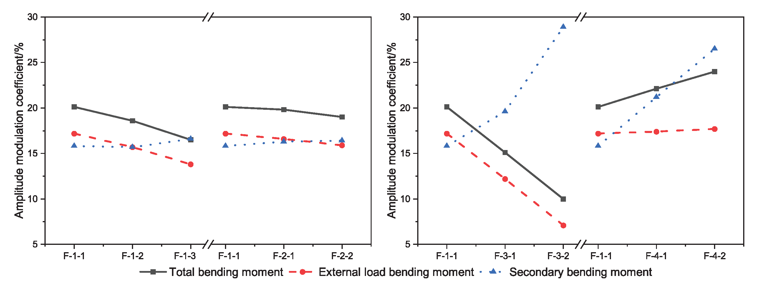
- There is a linear relationship between the secondary bending moment and the tendon stress increment. The distribution of the reinforcements and the eccentricity of the tendons has a large influence on the amplitude and sensitivity of the bending moment. The comprehensive bending moment modulation was between 10% and 24%, and the secondary bending moment modulation accounted for 15.8% and 28.9%.
- Increasing the axial force of the external prestress tendons or reducing the eccentricity and/or number of tensile reinforcements could reduce the modulation coefficient of the total bending moment and the external load bending moment.
- We propose a simplified equation for calculating the external load bending moment amplitude coefficient at ultimate. The proposed equation exhibits a quite good fit to test results.
Author Contributions
Funding
Institutional Review Board Statement
Informed Consent Statement
Data Availability Statement
Acknowledgments
Conflicts of Interest
References
- Lin, T.Y.; Burns, N. Prestressed Concrete Structure Design; China Railway Publishing House: Beijing, China, 1983; pp. 1–13. [Google Scholar]
- Zhao, G.T.; Duan, S.X.; Sun, B. Application on large-span reconstructed structure with external prestressing technology. J. Phys. Conf. Ser. 2021, 1885, 042042. [Google Scholar] [CrossRef]
- Yang, J.M.; Jung, J.Y.; Kim, J.K. Applicability of 2360 MPa grade prestressing steel strand: Performance of material, bond, and anchorage system. Constr. Build. Mater. 2021, 266, 120941. [Google Scholar] [CrossRef]
- Ahmed, A.; Guo, S.C.; Zhang, Z.H.; Shi, C.J.; Zhu, D.J. A review on durability of fiber reinforced polymer (FRP) bars reinforced seawater sea sand concrete. Constr. Build. Mater. 2020, 256, 119484. [Google Scholar] [CrossRef]
- Zhao, X.L.; Zhang, L. State-of-the-art review on FRP strengthened steel structures. Eng. Struct. 2007, 29, 1808–1823. [Google Scholar] [CrossRef]
- Guo, Z.H. Principles of Reinforced Concrete; Elsevier: Beijing, China, 2014; pp. 334–337. [Google Scholar]
- Skorupa, M.; Krobel, A.; Skorupa, A.; Machniewicz, T. Observations and analyses of secondary bending for riveted lap joints. Int. J. Fatigue 2015, 72, 1–10. [Google Scholar] [CrossRef]
- Lou, T.J.; Karavasilis, T.L. Numerical assessment of the nonlinear behavior of continuous prestressed steel-concrete composite beams. Eng. Struct. 2019, 190, 116–127. [Google Scholar] [CrossRef]
- Comité Euro-International du Béton. CEB-FIP Model Code 1990: Design Code; Thomas Telford Publishing: London, UK, 1993. [Google Scholar]
- Jian, B.; Wang, Z.L.; Wu, H. Test method for post-tensioned prestressed concrete continuous beams. J. Chongqing Jianzhu Univ. 1998, 38–43. [Google Scholar]
- Mattock, H.A.; Yamazaki, J.; Kattula, B.T. Comparative study of prestressed concrete beams, with and without bond. J. Proc. 1971, 68, 116–125. [Google Scholar]
- Lou, T.J.; Lopes, S.M.R.; Lopes, A.V. Nonlinear and time-dependent analysis of continuous unbonded prestressed concrete beams. Comput. Struct. 2013, 119, 166–176. [Google Scholar] [CrossRef]
- Lu, Z.T. Modern Prestressed Structural System and Design Method; Phoenix Science Press: Nanjing, China, 2010. [Google Scholar]
- Kaur, H.; Singh, J. A review on external prestressing in concrete. Int. Res. J. Eng. 2017, 4, 1801–1805. [Google Scholar]
- Allouche, E.N.; Campbell, T.I.; Green, M.F.; Soudki, K.A. Tendon stress in continuous unbonded prestressed concrete members—Part 1: Review of literature. PCI J. 1998, 43, 86–93. [Google Scholar] [CrossRef]
- Allouche, E.N.; Campbell, T.I.; Green, M.F.; Soudki, K.A. Tendon stress in continuous unbonded prestressed concrete members—Part 2: Parametric study. PCI J. 1999, 44, 60–73. [Google Scholar] [CrossRef]
- Harajli, M.H. Strengthening of concrete beams by external prestressing. PCI J. 1993, 38, 76–88. [Google Scholar] [CrossRef]
- Harajli, M.H.; Mabsout, M.E.; Jack, A.A.H. Response of externally post-tensioned continuous members. Struct. J. 2002, 99, 671–680. [Google Scholar]
- Lou, T.J.; Lopes, S.M.; Lopes, A.V. Factors affecting moment redistribution at ultimate in continuous beams prestressed with external CFRP tendons. Compos. B. Eng. 2014, 66, 136–146. [Google Scholar] [CrossRef]
- Abbas, T.; Tim, I.; Antony, D.; Mark, E.; Pedro, S. Prediction of capacity for moment redistribution in FRP-strengthened continuous RC T-beams. J. Compos. Constr. 2017. [Google Scholar] [CrossRef]
- Abbas, T.; Tim, I.; Antony, D.; Mark, E.; Pedro, S. Effect of Fiber-Reinforced Polymer Strengthening on Moment Redistribution in Reinforced Concrete Members. ACI Struct. J. 2018, 115. [Google Scholar] [CrossRef]
- ISO 6892-1:2019; Metallic Materials—Tensile Testing—Part 1: Method of Test at Room Temperature. ISO: Geneva, Switzerland, 2019.
- GB/T 30022-2013; Test Method for Basic Mechanical Properties of Fiber Reinforced Polymer Bar. China Building Materials Federation: Beijing, China, 2013.
- GB175-2007; Common Portland Cement. China Building Materials Industry Association: Beijing, China, 2007.
- GB/T 50081-2016; Standard for Test Method of Mechanical Properties on Ordinary Concrete. China Standard Press: Beijing, China, 2016.
- Tan, K.H.; Tjandra, R.A. Strengthening of RC continuous beams by external prestressing. J. Struct. Eng. 2007, 133, 195–204. [Google Scholar] [CrossRef]
- Cohn, M.Z. Continuity in Prestressed Concrete; Springer: Dordrecht, The Netherlands, 1986; pp. 189–256. [Google Scholar]
- Zheng, Y.X.; Guo, H.J.; Xie, N. Analysis of causes of bridge collapse accidents based on statistical analysis and preventive measures. China Foreign High. 2017, 37, 125–133. [Google Scholar]
- Opensess Manual: Modeling Commands. Available online: https://opensees.berkeley.edu/wiki/index.php/Modeling_Commands (accessed on 16 August 2022).
- Zheng, W.Z.; Cheng, W.H. Experiment and analysis on partial prestressed concrete continuous beams with unbonded CFRP tendon. Acta Mater. Compositae Sin. 2008, 25, 104–113. [Google Scholar]
- Zheng, W.; Bai, C.; Cheng, H. Experimental Study on Behaviors of Unbonded Prestressed Concrete Beams Reinforced with CFRP Tendons. Key Eng. Mater. 2009, 400, 567–573. [Google Scholar] [CrossRef]


| Diameter | Yield Strength/MPa | Tensile Strength/MPa | Elastic Modules/GPa | |
|---|---|---|---|---|
| Steel | 8 | 428 | 604 | 203 |
| 416 | 622 | 196 | ||
| 441 | 635 | 198 | ||
| 14 | 419 | 627 | 201 | |
| 434 | 613 | 204 | ||
| 422 | 641 | 197 | ||
| CFRP | 8 | - | 2052 | 148 |
| - | 1990 | 145 | ||
| - | 2019 | 142 |
| Cement | Medium Sand | Gravel | Water |
|---|---|---|---|
| 430 kg/m | 460 kg/m | 937 kg/m | 185 kg/m |
| ID | Compressive Strength/MPa | Elastic Modulus/MPa | Mean Compressive Strength/MPa | Mean Elastic Modulus/MPa |
|---|---|---|---|---|
| 1 | 27.7 | 27.2 | ||
| 2 | 26.8 | |||
| 3 | 27.1 |
| ID | /MPa | / | / | / | E/GPa | /mm | |
|---|---|---|---|---|---|---|---|
| Reference | F-1-1 | 1000 | 500 | 800 | 400 | 140 | 500 |
| G-1-1 | 1000 | 500 | 800 | 400 | 199 | 500 | |
| Initial Prestress | F-1-2 | 1250 | 500 | 800 | 400 | 140 | 500 |
| F-1-3 | 1500 | ||||||
| Section area of CFRP tendon | F-2-1 | 1000 | 550 | 800 | 400 | 140 | 500 |
| F-2-2 | 600 | ||||||
| Section area of Steal bar | F-3-1 | 1000 | 500 | 700 | 500 | 140 | 500 |
| F-3-2 | 600 | 600 | |||||
| Eccentricity | F-4-1 | 1000 | 500 | 800 | 400 | 140 | 450 |
| F-4-2 | 400 | ||||||
| Elastic Module | F-5-1 | 1000 | 500 | 800 | 400 | 200 | 500 |
| F-5-2 | 250 |
| ID | Reinforcement Coefficient | |||
|---|---|---|---|---|
| F-1-1 | 0.26 | 528.32 | −437.28 | 0.172 |
| F-1-2 | 0.29 | 586.49 | −494.6856 | 0.157 |
| F-1-3 | 0.32 | 644.43 | −555.7032 | 0.138 |
| F-2-1 | 0.27 | 555.47 | −463.4388 | 0.166 |
| F-2-2 | 0.28 | 581.95 | −489.6948 | 0.159 |
| F-3-1 | 0.26 | 525.30 | −461.4276 | 0.122 |
| F-3-2 | 0.26 | 535.02 | −496.8336 | 0.071 |
| ID | |||||||||
|---|---|---|---|---|---|---|---|---|---|
| L1-1A | 0.120 | −75 | 560 | 997 | 2.94 | 15.4 | −58.48 | −59.7 | 0.98 |
| L2-2B | 0.102 | −110.5 | 560 | 1027 | 4.41 | 16.3 | −84.68 | −86.8 | 0.98 |
| L3-3C | 0.102 | −104 | 550 | 1003 | 4.33 | 16.3 | −79.41 | −87.6 | 0.91 |
| L2-3A | 0.153 | −85 | 685 | 1056 | 5.39 | 13.9 | −65.45 | −66.3 | 0.99 |
| L2-1C | 0.183 | −96 | 670 | 984 | 3.52 | 12.5 | −79.73 | −72.4 | 1.10 |
| L1-3B | 0.277 | −78 | 956 | 1211 | 5.02 | 8.1 | −66.68 | −58.4 | 1.14 |
| L3-2A | 0.264 | −120 | 876 | 1117 | 9.20 | 8.8 | −99.78 | −98.9 | 1.01 |
| SB-2 | 0.077 | −69.58 | 916 | 1450 | 6.9 | 17.4 | −46.53 | −37.4 | 1.24 |
Publisher’s Note: MDPI stays neutral with regard to jurisdictional claims in published maps and institutional affiliations. |
© 2022 by the authors. Licensee MDPI, Basel, Switzerland. This article is an open access article distributed under the terms and conditions of the Creative Commons Attribution (CC BY) license (https://creativecommons.org/licenses/by/4.0/).
Share and Cite
Duan, N.; Zhang, J.-W.; Cheng, J. Simulation Research on Continuous Concrete Beams Reinforced with External Prestressed CFRP Tendons. Materials 2022, 15, 5697. https://doi.org/10.3390/ma15165697
Duan N, Zhang J-W, Cheng J. Simulation Research on Continuous Concrete Beams Reinforced with External Prestressed CFRP Tendons. Materials. 2022; 15(16):5697. https://doi.org/10.3390/ma15165697
Chicago/Turabian StyleDuan, Ning, Ji-Wen Zhang, and Jun Cheng. 2022. "Simulation Research on Continuous Concrete Beams Reinforced with External Prestressed CFRP Tendons" Materials 15, no. 16: 5697. https://doi.org/10.3390/ma15165697
APA StyleDuan, N., Zhang, J.-W., & Cheng, J. (2022). Simulation Research on Continuous Concrete Beams Reinforced with External Prestressed CFRP Tendons. Materials, 15(16), 5697. https://doi.org/10.3390/ma15165697