2.1. Materials Selection of Ultra-Thin Heat Pipes
Different materials have different thermal conductivity, and the selection of heat transfer materials significantly impacts the heat transfer performance of ultra-thin heat pipes. The materials used to prepare ultra-thin heat pipes mainly contain the shell material, the wick material, the mandrel material, the type of working fluid, etc. The selection of the materials for each working part should be comprehensively considered according to the thermal conductivity, machining performance, and compatibility between materials. The material and structure of wicks are complex, so they are explained and analyzed separately in
Section 2.2.
The pipe shell material of ultra-thin heat pipe is generally selected from copper, aluminum, stainless steel, and other materials. Whether it is compatible with the working fluid and the wick is the primary consideration in the selection of pipes. Yuan et al. [
19] developed an aluminum-based micro-grooved heat pipe using acetone as the working fluid, and the minimum thermal resistance can reach 0.029 KW
−1. However, aluminum is easily corroded by acid and alkali during long-term use, and the welding seal will also weaken the corrosion resistance of the aluminum pipe. At the concentration of 0.125 mol L
−1NaOH, the maximum resistance time of the heat pipe is only 110 min [
19]. Due to the incompatibility of aluminum and water, under the heating conditions of heat pipe operation, aluminum reacts with water to generate non-condensable hydrogen, so the water cannot be selected as the working fluid when aluminum is selected as the shell material [
20]. The non-condensable gas will hinder the gas–liquid circulation of the heat pipe, and the hindering effect is more obvious at low heating power [
20]. Copper heat pipes and stainless steel heat pipes generally use water, methanol, acetone, and ammonia as working fluids because of their ideal compatibility. Zhang et al. [
21] designed a heat pipe with a stainless steel pipe and a stainless steel powder wick. Compared with copper, it has excellent mechanical properties and has wider adaptability to the environment [
21]. Its maximum permeability is 1.299 × 10
−11 m
2 [
21]. The heat transfer effect is limited [
21]. The advantages and disadvantages of heat pipes of different pipe materials and their application fields are shown in
Table 1 [
11,
12,
13,
14,
15,
16,
17,
19,
21,
22,
23,
24]. Based on compatibility, the material with good thermal conductivity, long service life, good stability, low economic cost, good process performance, and easy processing is selected on a merit basis.
The flat-plate ultra-thin heat pipe is generally chosen as flat pipe; while for flat ultra-thin heat pipe used more widely, the cylindrical pipe is usually chosen. Currently, the copper is most commonly used as the heat pipe shell material, and it has good compatibility and wettability with the working fluid deionized water [
25,
26]. Copper is divided into oxygen-free copper, phosphorus deoxidized copper, common copper, silver copper, etc., in which the phosphorus deoxidized copper is generally chosen, in the TP1, as the shell material [
27,
28]. It does not occur with “hydrogen embrittlement” and brittleness at high temperatures, which affects the pipe processing [
27,
28]. In addition, TP1 has lower phosphorus content than TP2, so TP1 has better electrical and thermal conductivity.
Table 2 [
27,
28] gives the properties of TP1 optical pipes.
Whether powder sintering or mesh sintering, the wick needs to be fixed in the pipe using a mandrel first. The mandrel material is usually stainless steel (310S) or ceramic (boron nitride, BN) [
28]. In fabrication processing, the stainless steel mandrel is sprayed with boron carbide, as a release agent, in order to facilitate the removal of the mandrel after sintering and to increase the number of uses [
28]. This release agent attaches to the wick during the sintering process, which interferes with the return flow of the working fluid. Ceramic mandrels do not require treatment [
28]. In terms of reuse, the 310S mandrels can only be reused 5~7 times because of them being prone to rusting, while ceramic mandrels can be reused more than 30 times [
27]. In terms of the performance of the wicks, the performance of wicks using ceramic mandrels for solid-phase sintering is, mostly, slightly better than that of the wicks using 310S mandrels [
27]. Given the cost, 310S mandrels are less expensive, while ceramic mandrels are more expensive and fragile [
27]. In summary, 310S mandrels are suitable for small-scale experimental studies, while ceramic mandrels are suitable for large-scale production and applications.
The thermal properties of the working fluid and the heat transfer performance of the ultra-thin heat pipe are also closely related, and the selection of a suitable working fluid is critical, as shown in
Table 3 [
29,
30,
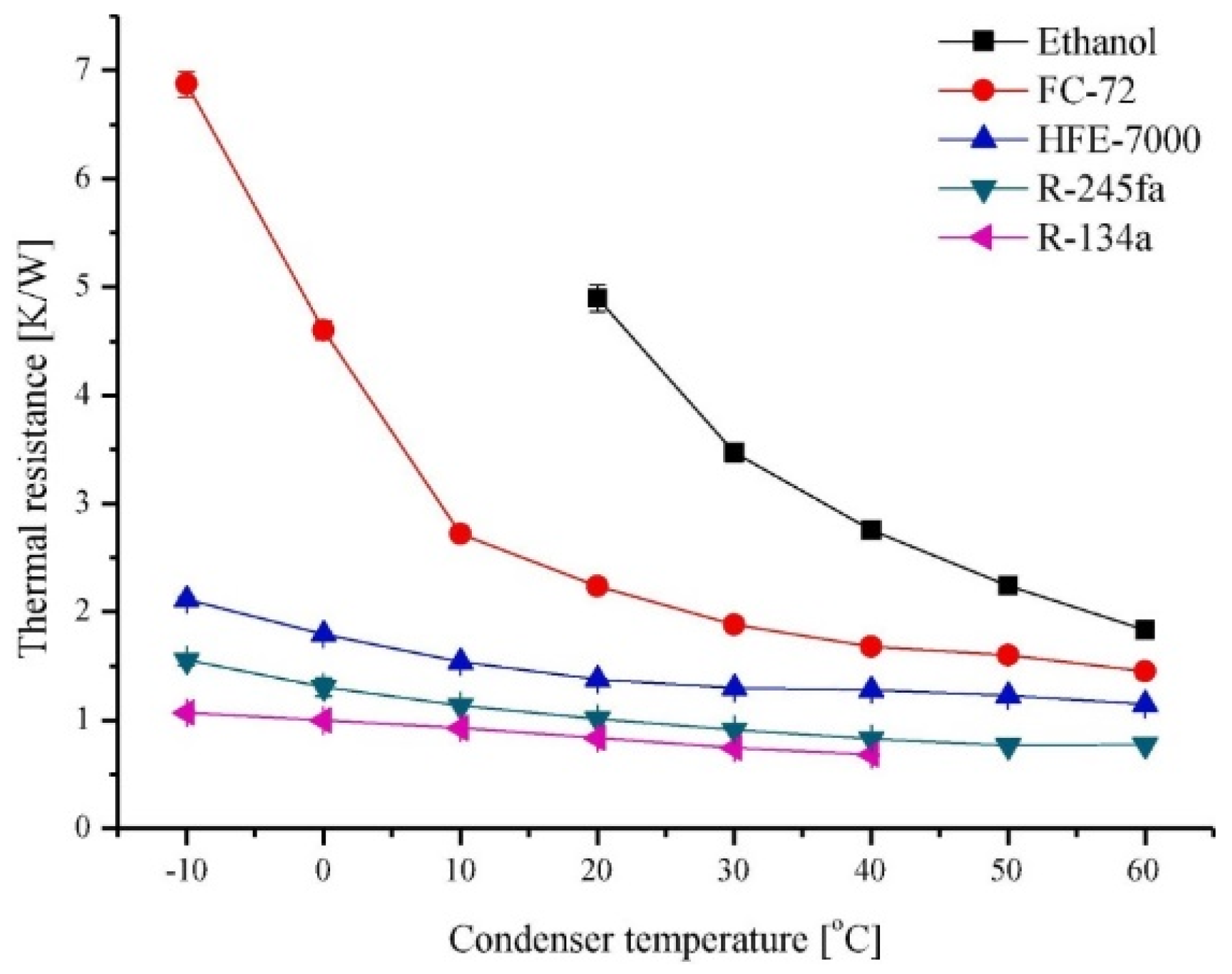
31]. To pursue a higher performance ultra-thin heat pipe, researchers have searched for numerous working fluids to investigate. Chao et al. [
32] compared the heat transfer characteristics of three different working fluids (acetone, ethanol, and methanol) through experiments and found that acetone is the most suitable working fluid under the lower heating power, while under the condition of higher heating power, ethanol has better heat transfer performance. Based on the previous work (
Figure 5 [
33]), Juno Kim and Sung Jin Kim [
33] selected five working fluids (ethanol, FC-72, HFE-7000, R-245fa, and R-134a), and each micro-pulsating heat pipe (MPHP) was filled with different working fluids, at room temperature, with the input power of Q = 15 W and the filling rate being 50%. The corresponding thermal resistance values were obtained by adjusting the different condenser temperatures [
33]. The experimental data showed that the micro-pulsating heat pipe with R-134a had the lowest thermal resistance, which was ten times smaller than the MPHP with FC-72 [
33]. In addition, the concept of a quality factor is proposed to facilitate researchers to select the optimal working fluid, with the lowest thermal resistance in pulsating heat pipes, more easily [
33]. Khan et al. [
34] constructed a hybrid nanofluid based on ethylene glycol with high thermal conductivity and excellent heat transfer potential. In addition, Khan et al. [
35] also built nanoliquid films on cylinders to achieve efficient heat transfer through spraying technology.
In summary, as a key factor directly affecting the heat transfer performance, the material selection needs to be considered from various aspects, such as material compatibility, mechanical strength, thermal conductivity, material cost, etc. For example, TP1 of smooth inner wall is preferred as the shell material. However, it is also necessary to take into account the actual situation to match the most suitable material in the actual application process.
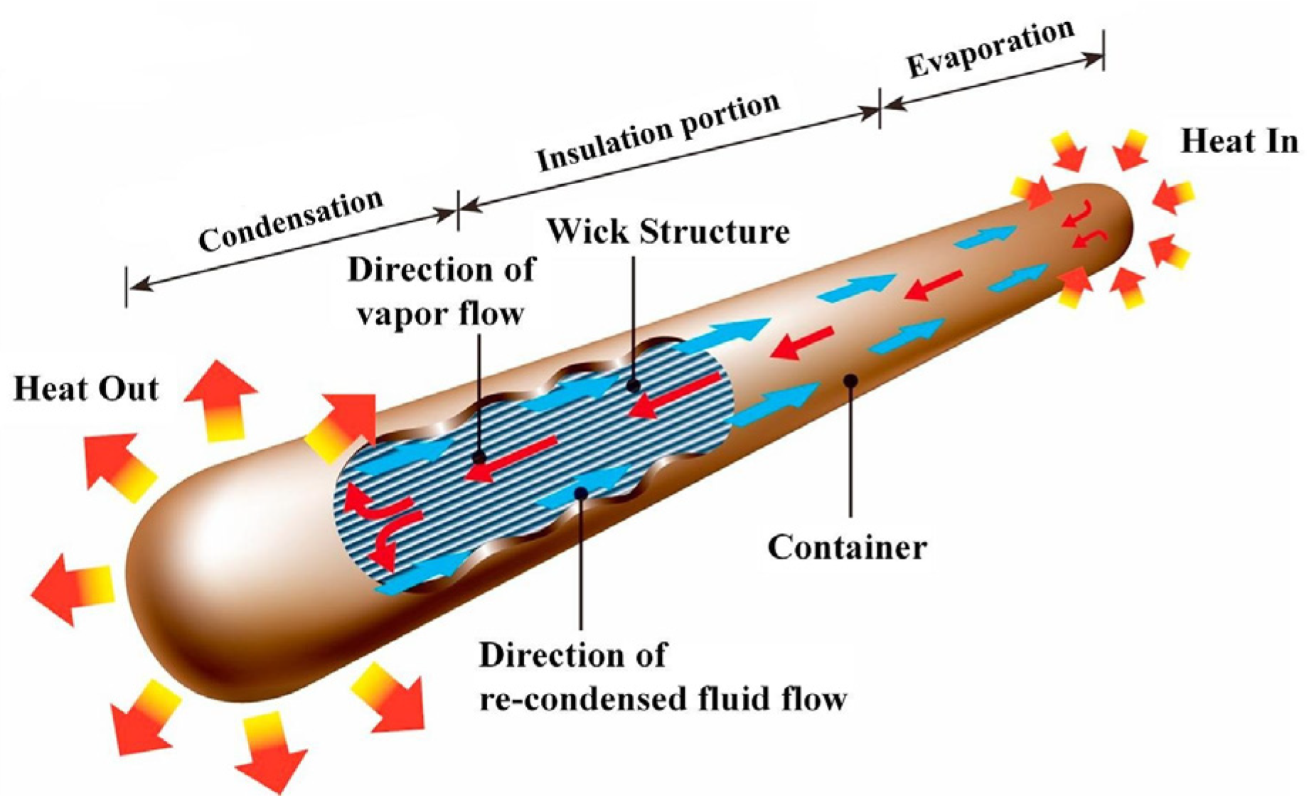
2.2. Wick Structure and Heat Transfer Performance
As the power element of an ultra-thin heat pipe, the wick needs to provide a high capillary force to facilitate the circulation of the working fluid for heat transfer, on the other hand the material should have good thermal conductivity. The types of wicks are very complicated, but the materials used to prepare the wicks are relatively simple. For most wicks, copper and some metals, such as stainless steel [
36], nickel [
37], or non-metallic ceramics [
38] and carbon fiber [
39], are used as the preparation material of wicks.
The raw material for wicks is generally in the form of powder or wire (fiber), and the different material forms imply different methods of forming processes. At present, most of the raw materials for wicks are in the form of copper powder, and a small number of copper wires (fibers) have been reported. As a new type of wick structure, copper wire sintered braided mesh core usually uses 0.04 mm or 0.05 mm diameter copper wire as the preparation material [
11,
18,
28,
40,
41]. Compared with the cutting method, the copper wire prepared by the wire drawing method has a smooth surface, uniform and accurate diameter, low production cost, and short preparation period [
28]. However, the wick has poor hydrophilicity and low capillary capacity, which affects the heat transfer capacity [
28]. Therefore, the wick made of copper wire needs to be super-hydrophilized [
28].
An ultra-thin heat pipe usually consists of a pipe shell, a wick, and a working fluid. As the core part, the shape and structure of the wick are critical to the performance of the ultra-thin heat pipe. The wick is used to provide power to the inside of the ultra-thin heat pipe through capillary action, which leads to the formation of a thermal cycle inside to transfer heat energy. According to the structure, it is divided into sintered wick, grooved wick, and composite wick [
42]. Among them, powder sintered wicks are the most widely used, as wicks rely on their cost-effectiveness [
40]. In contrast, the traditional screen sintered wicks have a large internal pressure drop, a low capillary pressure of wick, high thermal resistance of the contact with the shell, and a poor gravity resistance of the grooved wicks, which have a large fluctuation in performance under weightlessness and when overweight, so the application rate is relatively low [
43,
44,
45,
46,
47]. According to the data in
Table 4 [
43,
44,
45,
46,
47], it can be concluded that the maximum heat transfer capacity of a powder type wick is 30–70% higher than that of other types of wicks with the same thickness. In addition, the advantage of heat transfer performance is especially prominent, and the resistance to gravity is strong [
40].
With the development of heat pipe in fineness and the continuous exploration of heat pipe performance, it is found that there are problems in the heat transfer performance and stability of powder sintered heat pipe, which makes it difficult to ensure the high load operation of high heat flux equipment when the flattening thickness is small [
48]. As shown in
Figure 6 [
48], with the reduction in the flattening thickness, the partial deformation of the powder sintered wick structure affects the porosity of the wick [
48]. The change of porosity directly affects the heat transfer performance of the heat pipe. The powder-sintered wick structure easily to produces cracks or even falls off when the thickness of the flattening is thin, which will also affect the heat transfer performance and stability of the heat pipe to different degrees [
48]. Li et al. [
49] developed a new ultra-thin heat pipe for cell phone cooling systems, which adopts a spiral woven mesh wick structure with good heat transfer and low manufacturing cost, and they began to gradually replace powder sintered heat pipes in the field of ultra-thin heat pipes. However, the spiral woven wire mesh wick has the same problem of low capillary capacity as the traditional mesh wick [
50]. To solve this problem, Tang et al. [
50] introduced the chemical deposition method by depositing the woven copper wire mesh into a 250 mL mixture of 10 mL/L NaOH and 0.5 mol/L K
2S
2O
8, which significantly improved the capillary capacity of the spiral woven wire mesh wick. In addition, the heat transfer performance was tested by varying the sintering temperature and chemical deposition time, and the experimental data showed that the best heat transfer performance was obtained from the group with the sintering temperature of 500 °C and chemical deposition of 15 min for the wick [
50].
The spiral woven mesh is made by the interlaced weaving of the knitting machine, which is very suitable as wick structure of ultra-thin heat pipe [
50]. It has the advantages of compact structure, regular pore, good flexibility, a simple manufacturing process, and low manufacturing cost. The braiding starts by combining several copper wires into one strand, rotating multiple strands on the cylindrical mandrel through the braiding machine, and interweaving them into a circular spiral braided mesh structure [
50]. The double-layer spiral woven mesh is then placed in the center of the machine rotating wheel and woven again to form a circular double-layer structure with close contact [
50]. Tang et al. [
40] studied the effect of different heat pipe thicknesses on the spiral woven mesh type ultra-thin heat pipe, as shown in
Figure 7 [
40]. Most of the pores disappear when the thickness of the heat pipe decreases to 0.8 mm [
40]. The structure of 0.05 mm copper fiber spiral braided mesh wick was seriously damaged, and the heat pipe was basically in a failure state [
40]. Similarly, Zhou et al. [
51] also explored in the spiral woven mesh type ultra-thin heat pipe, and it can be seen, from
Table 5, that the maximum heat transfer capacity of the ultra-thin heat pipe is only 3.6 W when the thickness is 0.4 mm. It is difficult to solve the problem of heat pipe failure, when the thickness is low, by reducing or increasing the diameter of copper wire. When the diameter of the copper wire is too small, the mechanical strength of the wick is insufficient. In addition, the structure is easily damaged when the phase change flattens or bends. However, the diameter of copper wire should not be too large because it is limited by the thickness of heat pipe.
As shown in
Table 5 [
11,
40,
41,
51,
52], in pursuit of a heat pipe with thinner thickness and better heat transfer performance, many scholars have performed further studies on wire mesh braiding structure. Yang et al. [
52] designed a composite braided mesh wick (B
4) with a double-layer structure, which was made by wrapping 0.1 mm copper wire with 0.05 mm copper wire. Compared with traditional spiral braided mesh wick (B3), the overall heat transfer performance improved by 32.5% [
53]. Zhou et al. [
41] designed double-layer spiral woven mesh wicks (C
1, C
2) with 0.04 mm and 0.05 mm copper wires, according to the strand structure. In addition, a single-hole, three-layer spiral woven mesh wick (C
3), consisting of only 0.04 mm copper wires, was also designed [
41]. The results showed that the maximum heat transfer capacity of the three-layer mesh wick C
3 was up to 26 W, and the minimum thermal resistance of C
2 was at 0.101 °C/W [
41]. The maximum heat transfer capacity of C
2 was 7.70% lower than that of C
3, but the thermal resistance was reduced by 6.32–25.90% [
41]. In addition, the copper wire is reduced by 22%, and C
2 is the best from both the cost and performance perspectives, which indicates that the heat transfer performance can be effectively improved by increasing the number of layers, but the comprehensive performance of the double braided mesh wick is the best [
41]. To further explore the potential performance of the double-weave spiral mesh wicks with double holes, Zhou et al. [
18] also designed eight types of double-weave spiral mesh wicks using 0.04 mm and 0.05 mm copper wires with different ratios of strands, and then, they tested the performance of heat transfer separately. The total thermal resistance was reduced by 27.53–42.92% compared to the conventional woven mesh wick. A larger pore space is formed between copper wires of different diameters in the hybrid weave, and a relatively smaller pore space is formed by copper wires of the same diameter (
Figure 8 [
18]). The larger pore space can improve the permeability of the wick, and the smaller pore space can enhance the capillary capacity to accelerate the thermal circulation, as well as reduce the overall size of the wick to leave more space for the steam, as well as liquid channels, inside the heat pipe [
18]. The above study proves that the multi-size pore spiral woven mesh wick, prepared by mixing copper wires, can effectively improve the heat transfer performance of the ultra-thin heat pipe. According to the test data [
11,
40,
41,
51,
52], it can be found that B
4 is better, and the thickness of the ultra-thin heat pipe (B
4) is thinner with the same maximum heat transfer capacity.
In the above studies, the toroidal spiral woven mesh was selected for wick structure, which squeezes too tightly and seriously affects the heat transfer during the phase change flattening process. In order to meet the requirement of 0.4 mm thickness of the smartphone heat sink system, Zhou et al. [
11] designed a new ribbon spiral braided mesh wick, using 0.04 mm copper wire, consisting of 17 strands of copper wire, and they set three different wicks (A
1, A
2, and A
3) by changing the number of copper wires per share to conduct performance tests in an ultra-thin heat pipe with a thickness of 0.4 mm. The experimental data shows that the A
3 with 11 copper wires per share has the best heat transfer performance, with a maximum heat transfer capacity of 5.25 W [
11]. However, A
2 with 10 copper wires per share is more suitable if production cost is taken into account, and the maximum heat transfer capacity can still reach 5 W with 17 fewer wicks [
11].
As shown in
Table 5 [
11,
40,
41,
51,
52], by comparing B
1, B
2, D
1, and D
2, it is found that the effect of chemical oxidation on heat transfer performance increases with the increase in heat pipe thickness, and the maximum heat transfer capacity increases to 45% when the thickness of heat pipe is 1.2 mm. By analyzing the data of five types of wicks from C
1 to C
5, it can be seen that the number of layers, strand structure, number of strands, and the total number of copper wires all affect the heat transfer performance to different degrees [
54]. When the thickness of the ultra-thin heat pipe is 1 mm, the maximum heat transfer capacity is improved by about 17.65% of B
1 and B
2, which can prove that the heat transfer performance can be increased by chemical oxidation [
40]. The comparison of B
2, B
4, and the copper powder wick in
Table 5 [
11,
40,
41,
51,
52] conveyed that the maximum heat transfer capacity was close to the same, but in the comprehensive multifactor consideration, the manufacturing process of powder wick is more complicated, and the manufacturing yield is lower. Therefore, the spiral woven mesh wick is more suitable. In the ultra-thin heat pipe, with thickness of 1.1~1.2 mm, the maximum heat transfer capacity is 29 W [
40], which is a significant improvement in heat transfer performance compared with the above-mentioned lower thickness heat pipes, and it indicates that the heat pipe thickness is an important factor affecting the heat transfer of ultra-thin heat pipes. When the thickness of the ultra-thin heat pipe is 0.4 mm, the volume in the cavity is severely reduced, and the heat transfer performance of the wick decreases tremendously. The performance requirements in all aspects are more stringent, and the ribbon spiral braided wick is the most optimal choice at present. There are still gaps concerning the total number of copper wires, strands, and multi-size pores. The field of heat pipes with 0.4 mm thickness is yet to be developed, and the numerical model regarding the ultimate ultra-thin thickness (the thickness less than 4 mm) needs to be developed separately. The volume of wick and the cavity space need to be adjusted for the optimal ratio, and the heat pipe shell and wick need excellent mechanical strength, in the phase change, when flattening to the ultimate thickness. Different experimentalists have different data measurement methods and instruments. The internal factors and external environmental factors of the heat pipe will differ, which need to be further verified, mutually, through theoretical analysis and experimental simulations.
Table 5.
Structural parameters and maximum heat transfer capacity of spiral braided mesh wick ultra-thin heat pipe.
Table 5.
Structural parameters and maximum heat transfer capacity of spiral braided mesh wick ultra-thin heat pipe.
| Number. | Braided Shapes | Thickness (mm) | Number of Layers | Strand Structure (mm) | Number of Shares | Total Number of Copper Wires | Maximum Heat Transfer Capacity (w) |
|---|
| A1 | Banding [11] | 0.4 | 2 | 0.04 × 9 | 17 | 153 | 4.25 |
| A2 | Banding [11] | 0.4 | 2 | 0.04 × 10 | 17 | 170 | 5 |
| A3 | Banding [11] | 0.4 | 2 | 0.04 × 11 | 17 | 187 | 5.25 |
| A4 | Annular [51] | 0.4 | NA | NA | NA | 96 | 3.6 |
| B1 | Unoxidized ring shape [40] | 1 | NA | 0.05 × 6 | NA | NA | 17 |
| B2 | Annular [40] | 1 | NA | 0.05 × 6 | NA | NA | 20 |
| B3 | Annular [52] | 1 | 1 | NA | NA | 152 | 15 |
| B4 | Annular [52] | 1 | 2 | NA | NA | 224 | 20 |
| C1 | Annular [41] | 1.1 | 2 | 0.04 × 4 + 0.05 × 2 | 24 | 288 | 18 |
| C2 | Annular [41] | 1.1 | 2 | 0.04 × 5 + 0.05 × 2 | 24 | 336 | 24 |
| C3 | Annular [41] | 1.1 | 3 | 0.04 × 6 | 24 | 432 | 26 |
| C4 | Annular [41] | 1.1 | 2 | 0.04 × 7 | 24 | 336 | 13 |
| C5 | Annular [41] | 1.1 | 2 | 0.05 × 7 | 24 | 336 | 15 |
| D1 | Unoxidized ring shape [40] | 1.2 | NA | 0.06 × 6 | NA | NA | 20 |
| D2 | Annular [40] | 1.2 | NA | 0.05 × 6 | NA | NA | 29 |
Based on the structure and data of the ultra-thin flat heat pipe, ten similar articles are summarized to facilitate the comparative analysis of the factors affecting the heat transfer of the heat pipe. The structure is shown in
Figure 9 [
11,
18,
40,
41,
45,
48,
50,
52,
55,
56], and the corresponding temperature profile is shown in
Figure 10 [
11,
18,
40,
41,
45,
48,
55,
56]. Relying on the copper pipe as the carrier, the various derivatives (copper foam, mesh, spiral woven mesh, copper powder) are used to build wick structures, striving to achieve better heat transfer performance in small spaces.
The structure of wire mesh + SWM + wire mesh (
Figure 9j [
56]) can achieve the maximum heat transfer capacity of 38 W (
Figure 10i [
56]), and the temperature difference between the evaporation end and the condensation end is nearly 10 °C [
56]. The heat transfer effect is more significant under high heating power [
56]. Wire mesh can effectively retain pores when in the flattening process, and it has the advantages of a strong compression flattening ability and stable structure [
56]. SWM makes the reflux resistance of condensate small, and it makes the vapor–liquid circulation more smooth [
56]. The combination of wire mesh and SWM effectively solves the problem of excessive heat resistance between SWM and copper tube, and redox further improves its heat transfer performance [
56]. However, it is difficult for this structure to function at the extreme ultra-thin thickness. On the one hand, it is the cost problem caused by the precise processing technology; on the other hand, the internal collapse of the SWM during extreme compression causes the porosity to be too low.
Comparing the temperature profile of b and f in
Figure 10 [
11,
45], the maximum heat transfer capacity and temperature difference are both 5 W and 4 °C [
11,
45]. The performance of the structure in
Figure 9h [
11] is significantly better than that of the structure in
Figure 9c [
45] at low heating power. However, the overall temperature of the structure in
Figure 9c [
45] is lower than the structure in
Figure 9h [
11] when the heat pipe is in steady state operation. In terms of the overall size of the heat pipe, the structure in
Figure 9c [
45] and the structure in
Figure 9h [
11] are roughly the same. The flattened thickness of the structure in
Figure 9c [
45] is twice that of the structure in
Figure 9h [
11], but the width of the heat pipe of the structure in
Figure 9h [
11] is 285.2% of that of the structure in
Figure 9c [
45]. In the structure of the wick, the structure in
Figure 9c [
45] uses foamed copper mixed with mesh, and the structure in
Figure 9h [
11] is SWM for a single structure. Overall, the heat transfer performance of the two is roughly the same, but the processing cost of the structure in
Figure 9h [
11] is better than that of the structure in
Figure 9c [
45] due to its single structure, and its practicability is wider because of the 0.4 mm flattening thickness.
Comparing the structure in
Figure 9c [
45] and the structure in
Figure 9e [
55] with similar wick structures, the internal space of the structure in
Figure 9e [
55], of the heat pipe, is about three times that of the structure in
Figure 9c [
45], and the maximum heat transfer capacity of the structure in
Figure 9e [
55] is 170% of the structure in
Figure 9c [
45], as shown in
Figure 10d [
55] and
Figure 10b [
45]. The advantage in the internal space of the heat pipe does not bring ideal heat transfer to the structure in
Figure 9e [
55], and the structure of copper + mesh (
Figure 9c [
45]) is smaller than the mixing of meshes of different meshes.
Compared to the temperature profiles in
Figure 10a [
18],
Figure 10g [
41], and
Figure 10h [
41], both heat pipes have the same shell size and type of wick, and the only difference is that the composition ratio of the strands is slightly different during weaving. The overall temperature of the heat pipe in steady state operation is roughly the same. The maximum heat transfer capacity is 20 W, 24 W, and 26 W, respectively, and the temperature difference is 5 °C, 3 °C, and 5 °C [
18,
41]. It is proven that, by adjusting the number of strands, the heat transfer performance of the heat pipe can be slightly improved.
Compared with the structures in
Figure 9d [
48],
Figure 9g [
40], and
Figure 9j [
56], the structure of a double half-moon type (
Figure 9d [
48]), based on the mixing of copper powder with different meshes, also has a good performance, but the heat pipe of 200 mm length does not improve heat transfer performance. The axial temperature distribution of other heat pipes also shows that the length of the heat pipe has little effect on the heat transfer performance [
40,
48,
56]. In the heat pipe, with a flattened thickness greater than 1.1 mm, the copper powder wick heat pipe has a lower production cost than the SWM heat pipe. In addition, it has a larger application with the heat transfer performance of excellence [
48]. The data of the structure in
Figure 9g [
40] and the structure in
Figure 9j [
56] are similar in all aspects. From the structure in
Figure 9j [
56], it can be seen that the combination of the mesh and the SWM is not regular, and the contact of the joint parts is not regular. In addition, thermal resistance limits its heat transfer performance [
56].
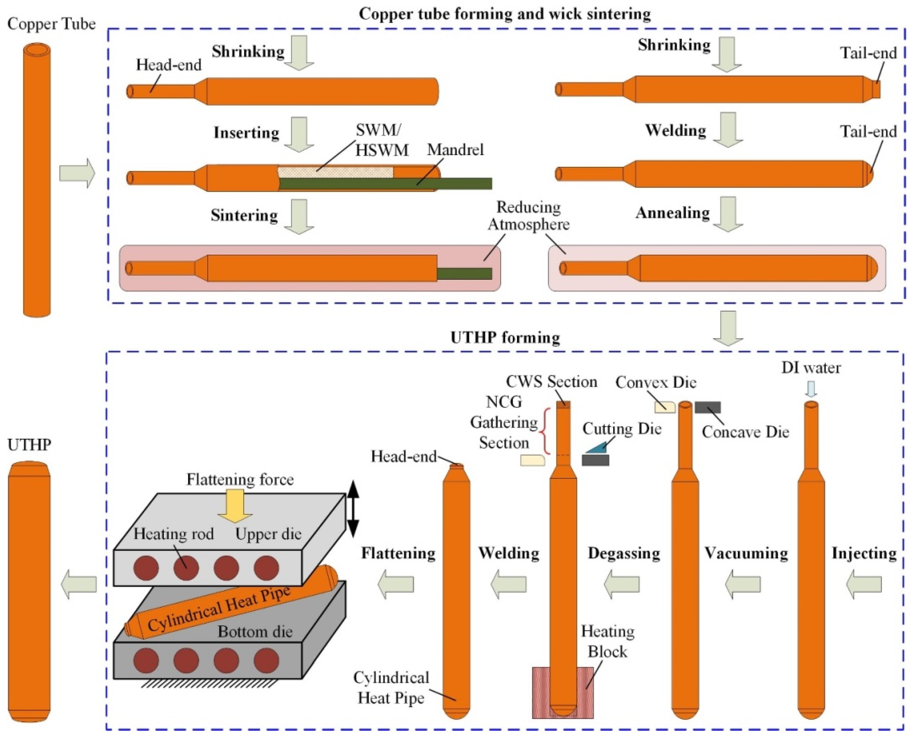
2.3. Formation of Ultra-Thin Heat Pipes
The head and tail of the heat pipe need to be necked (the vacuum pumping end is proposed to be the tail). In order to facilitate the welding and sealing of ultra-thin heat pipe and the cold welding of the second degassing process, the necking taper is matched with the front end of the mandrel to prevent the leakage of wick material [
57]. In addition, the local pressure drop, caused by the sudden change of pipe diameter, is also conducive to protecting the working fluid in the heat pipe [
57]. Conventional necking processes include rotary forging, extrusion, spinning, and direct punching [
57]. As spinning and direct punching cause greater damage to the pipe, affecting the subsequent forming of the heat pipe, ultra-thin heat pipe mainly uses rotary forging and extrusion of two radial forging neckings [
57].
Rotary forging necking is a process in which the hot pipe is continuously radially forging the outer wall of the hot pipe, by a high-speed rotating forging die, to reduce the diameter [
57,
58]. The forming force of the intermittent radial forging process is small, so it is suitable for thin-walled and large reduction ratios of tubing reduction [
58]. For an ultra-thin hot pipe with thin wall thickness, the necking process is easy to spin off and cause deformation of the pipe body, so it is needed to reduce the spindle speed and adjust the rotary forging necking die [
59]. Rotary forging has high requirements on the precision and impact resistance of the mold, and the required equipment is complex and precise [
59]. In addition, the operating cost of rotary forging is high, and there is a lot of noise during the operation. [
59].
The extrusion neck process is that the forming die rotates and extrudes the copper pipe, which is driven by the electric spindle [
60]. The heat generated by rotating friction can reduce the deformation resistance of the copper pipe, but it can also cause oxidation of the copper pipe [
57]. The extrusion neck has low dependence on the overall mold and does not require high precision, so the process cost is low [
57]. Wang [
60] et al. verified the results through experimental analysis and simulation with ABAQUS finite element software, which showed that the optimal necking process parameters for copper pipes, with outer diameter of 5 mm and wall thicknesses of 0.1, 0.2 and 0.3 mm, were a die feed rate of 50 mm/s and die speed of 4800 r/min.
The sintering process is important in the heat pipe manufacturing process, which is based on the principle of the diffusion bonding of metals at high temperatures. Sintering enables the formation of the wick and the combination of the wick and the pipe wall to achieve a certain bond strength and porosity to enhance the heat transfer capability of the heat pipe. Metal powder sintering is formed by the surface diffusion of the sintered neck, while metal fibers and wire mesh also need to diffuse through the volume and grain boundaries [
61]. The sintering process is sequentially divided into four stages: reduction, sintering, holding, and cooling [
53]. After a series of comprehensive analyses, Li et al. [
61] found that the sintering temperature of 140~170 μm diameter copper powder was generally controlled at about 900~950 °C, holding for about 30~60 min, and the various properties of the prepared wick were better. While the sintering temperature of copper fiber and copper wire is usually lower than that of copper powder [
61], the sintering neck becomes larger at too high of a sintering temperature, causing the pores to decrease, thus increasing the bonding strength of the wick and the difficulty of drawing the mandrel [
61]. Copper powder sintering is more adequate than copper fiber sintering, which is an important reason for the higher capillary capacity of copper powder sintered wick [
61].
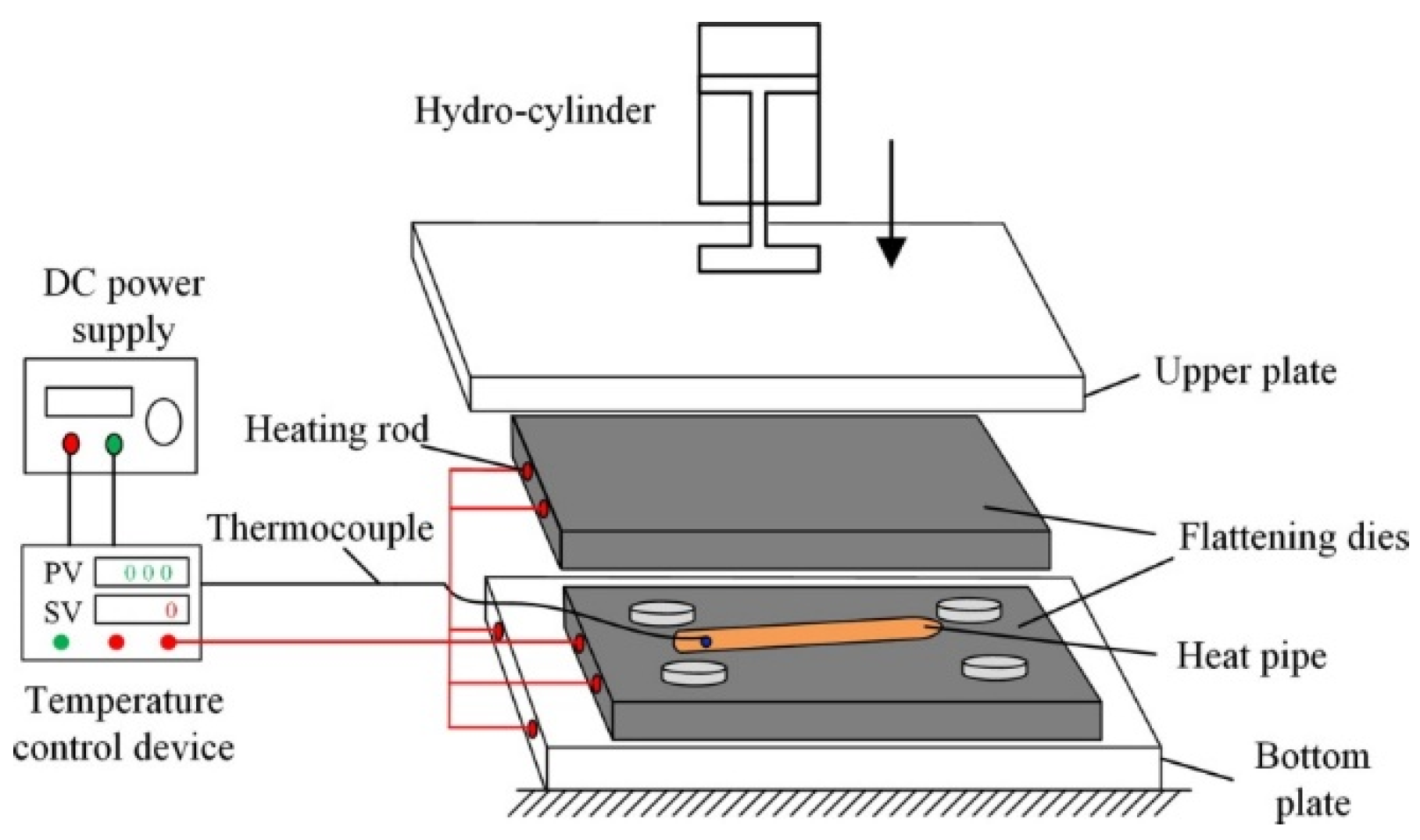
The phase change flattening process, which is very important for the forming of ultra-thin heat pipes, was developed by Jiang et al. [
54], based on the principle of steam pressure of the working fluid inside the heat pipe, to overcome the buckling phenomenon. The principle of the phase change flattening process is shown in
Figure 11 [
47], and Li et al. [
47] pointed out that this process is more flexible and convenient than the welding process, as well as more suitable for industrial mass production. Using stamping die to compress the heat pipe as the core of its process, obvious elastic-plastic deformation occurs during the stamping process, and the vapor pressure in the tube needs to be kept constant during the stamping process [
47]. In order to ensure that the ultra-thin heat pipe does not buckle during the phase change flattening process and does not rupture and scrap due to excessive vapor pressure, Tang et al. [
62] combined the Von Mises yield quasi with the stress analysis of the phase change flattening process, and through repeated experimental tests, the optimal heating temperature for the phase change flattening of ultra-thin heat pipes was derived to be 220 °C.
2.4. Surface Modification
In the gas–liquid phase change heat transfer process of heat pipes, pool boiling is the main means of dissipating the larger heat fluxes [
63]. Changes in both surface structure wettability and roughness affect the contact effect between solid and liquid. Thus, the state of boiling heat transfer was changed [
64]. The hydrophilic surface can effectively improve the surface wettability and facilitate the flow of liquid to nucleation sites [
65], while the heat transfer contact area and the number of nucleation sites increase [
66]. In addition, the hydrophilic surface lead to the turbulence intensity and heat transfer coefficient of the working fluid in the pipe increasing [
67], and it can successfully eliminate the inhibitory effect of bubble separation due to the network of connected micropores on the surface of the wick [
68]. Studies have shown that modifying the surface of the heat pipe wick into a super-hydrophilic surface has a positive effect on the heat transfer performance of the heat pipe. The formula, based on the maximum capillary pressure ∆
Pc,max of the wick, can also confirm this view. ∆
Pc,max can be obtained from the Young–Laplace formula [
69]:
Here, σ is the surface tension of the working liquid; θ is the contact angle of the working liquid; reff is the effective capillary radius of the wick. From the equation, it can be concluded that, when the effective capillary radius of the wick is determined, the maximum capillary pressure is only determined by the surface tension and contact angle, and the maximum capillary pressure of the wick can be effectively increased when the wick is changed to a superhydrophilic surface by surface modification.
To investigate the pool boiling heat transfer properties, foam metal was used as the experimental object, and the foam metal surfaces were hydrophilically and hydrophobically modified. Meanwhile, foam metal without surface modification was added as the reference group [
70]. The experimental data show that the hydrophobic surface has higher heat transfer performance at low heat flux conditions [
70]. However, the heat transfer performance of the hydrophilic surface gradually improved with increasing heat flux, and the best heat transfer performance was achieved when the heat flux exceeded 4 × 10
5 W/m
2 [
70]. In addition, the reinforcement effect of low porosity hydrophilic surfaces is better than that of hydrophobic surfaces [
70]. To further investigate the effect of surface structure wettability on boiling heat transfer, Jo et al. [
71] analyzed the boiling heat transfer phenomena of different wettability surfaces (hydrophilic surface, hydrophobic surface, and heterogeneous wettable surface composed of a hydrophilic surface with hydrophobic dots) using surface modification techniques of microelectromechanical systems (MEMS) and high-speed visualization techniques. As shown in
Figure 12 [
71], (1) to (6) show the boiling heat transfer phenomena at different times, and it can be seen that hydrophilic surfaces are more favorable for the generation and separation of bubbles. However, when the contact angle of the material surface is greater than 90°, the direction of the force changes and inhibits the contraction of the bottom of the bubble when it separates from the surface [
72]. Therefore, the contraction of the bottom of the bubble, on a hydrophobic surface, is subject to greater resistance [
72].
Zhuo et al. [
65] conducted experiments with untreated hydrophilic silicon wafers and super hydrophilic silicon wafers treated by silicon dioxide deposition. The experimental results show that the hydrophilic surface appears with a drying phenomenon under the condition of high heat flux, which leads to the decline of heat transfer performance [
65]. However, there is no drying on the super hydrophilic surface, the pressure drop is stable, and the heat transfer performance is more stable because there is no deposited silica, and the wettability of the super hydrophilic surface is better [
65].
All of the above studies are based on the effect of surface modification on boiling heat transfer, and it is well demonstrated that modifying the surface of heat pipe wicks to superhydrophilic surfaces has a positive effect on the heat transfer performance of heat pipes. Low capillary capacity has been a key factor hindering the development of screen sintered wick heat pipes, and the application of superhydrophobic modification, in the field of heat pipes, can significantly improve the hydrophilic performance of screen wicks and improve the capillary capacity. In addition, for the superhydrophobic modification, Tang [
28] used the superhydrophobic surface with low surface energy in the condensing section to make it difficult for the condensate droplets to maintain the water droplet shape and, thus, keep the droplet condensation, which effectively reduces the thermal resistance and improves the heat transfer performance.
Because of the high coupling inside the heat pipe, surface modification affects the vapor–liquid contact region and solid–liquid contact region inside the heat pipe, and the thermodynamic phenomena generated in the vapor–liquid contact region and solid–liquid contact region inside the heat pipe have been systematically analyzed by developing transient and steady-state models [
73,
74]. Harmand et al. [
73] proposed a transient model that can capture the thermodynamic cycle inside the heat pipe. This model couples a 3D transient thermal model with a 2D hydrodynamic model based on mass conservation equations, analyzes the importance of heat transfer in the microfilm region at the vapor–liquid interface, and can be used to predict the avoidance of local hot spots using simulations [
73]. Ranjan et al. [
74] used a 3D numerical model of heat pipe transients to analyze the effect of contact angle and porosity on the mass flux in the pores of the liquid wick, and they found that the change in mass flux is inversely proportional to contact angle and porosity due to the fact that it is the solid-liquid interface. A thin film curved liquid surface that can enhance the convection effect in a small way is formed at the contact interface, as shown in
Figure 13 [
74], and the curved liquid surface keeps shrinking when the contact angle and porosity increase, which leads to the decrease in mass flux.
In order to study the motion law of the vapor–liquid phase change inside the heat pipe more in-depth, Fang et al. [
75] proposed a three-dimensional liquid–gas phase change lattice Boltzmann model, which can operate in complex transient environments and effectively overcome the challenges posed by coupled heat transfer inside the heat pipe, as well as eliminate the assumptions that the wick must be saturated and that the porous wick structure is a continuous medium in previous studies and can simulate any wick structure [
75]. It is found that, as the heat flux rises, the working fluid retreats into the groove wick and forms a curved meniscus at the solid–liquid interface, forming a pressure difference with the flat meniscus at the condensing end to obtain sufficient capillary force [
75].
In the heat transfer process of the heat pipe, the heat transfer performance of the heat pipe and the internal vapor–liquid phase change process are inextricably linked. Cui et al. [
76] investigated the bubble growth process in the flat region of the wick by Mixture model and experiment, and they deduced that the bubble growth rate is proportional to the heat flux and the surface area of the wick. Therefore, increasing the surface area and surface roughness of the wick has a positive effect on the heat transfer of the heat pipe [
76]. As shown in
Figure 14 [
76], nanoscale nucleated bubbles are generated on the solid–liquid surface and gradually form a vapor film, which then eventually becomes millimeter-sized bubbles by separating and merging.


