
Application of a New Alloy and Post Processing Procedures for Laser Cladding Repairs on Hypereutectoid Rail Components

Abstract
:1. Introduction
2. Materials and Methods
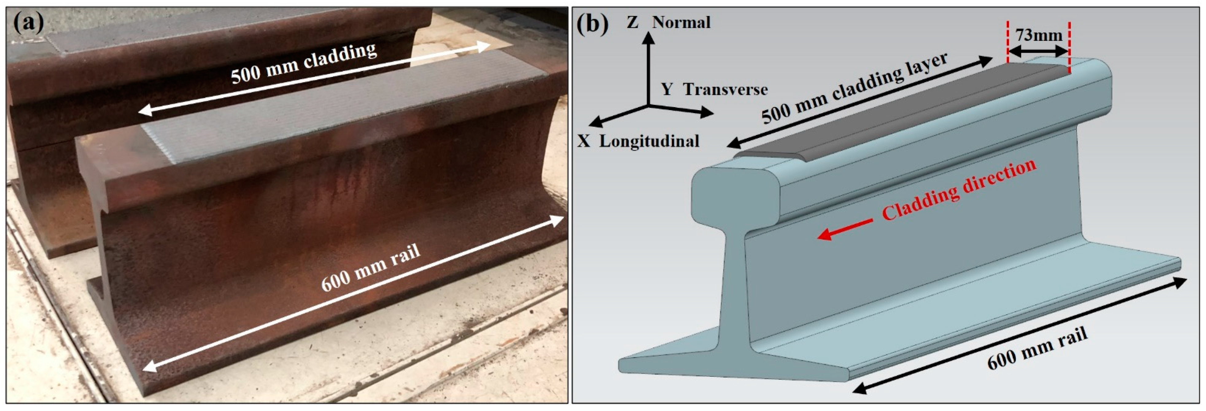
2.1. Laser Cladding
2.2. Cladding Materials and Sample Preparation
2.3. Heat Treatment Processes
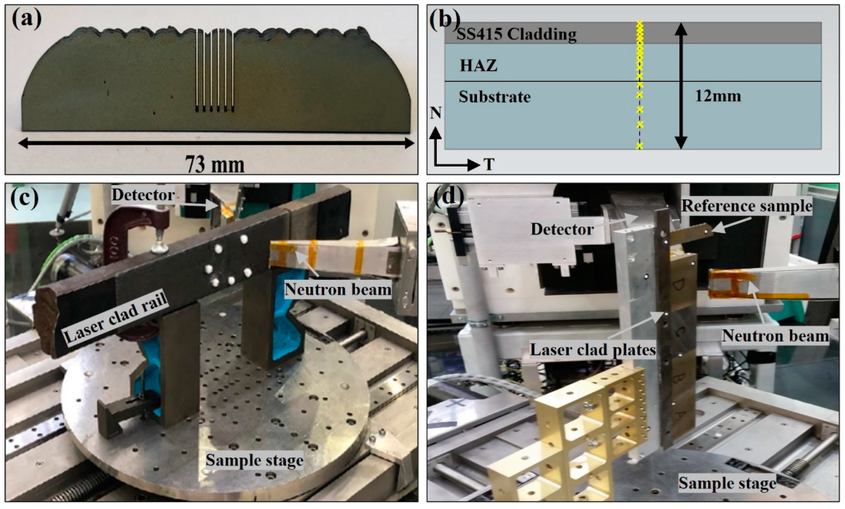
2.4. Residual Stress Measurement
3. Results
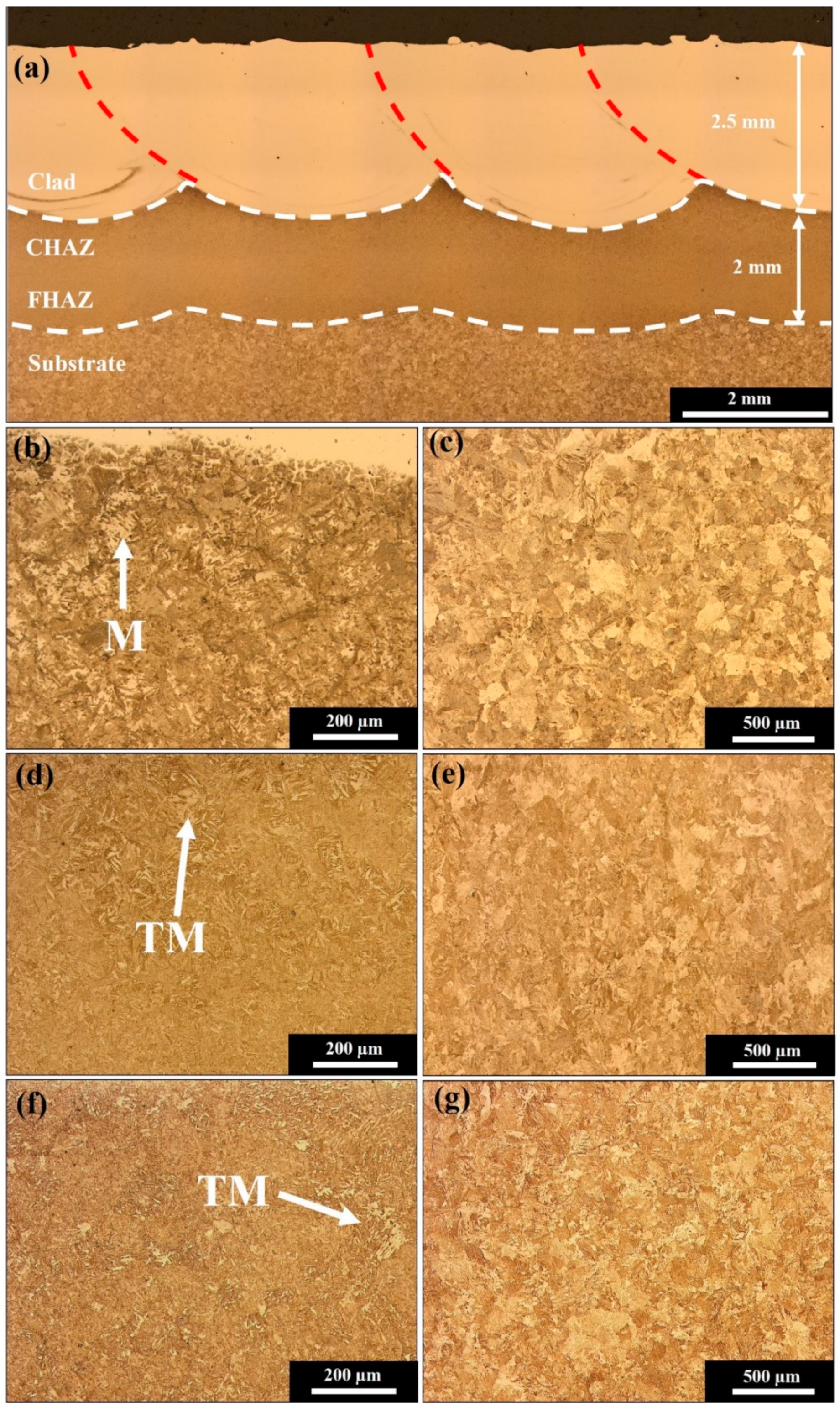
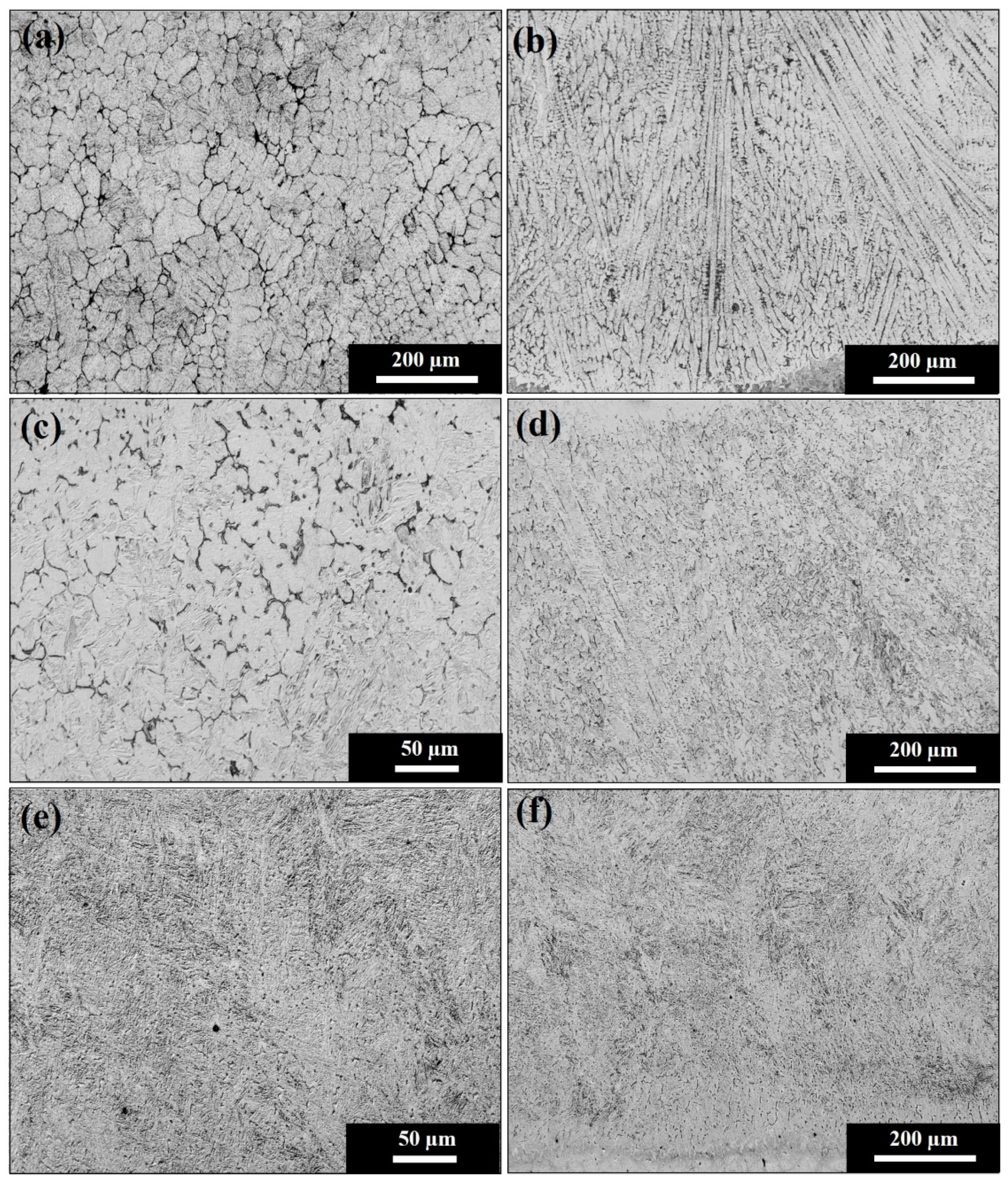
3.1. Microstructure
3.2. Residual Stress
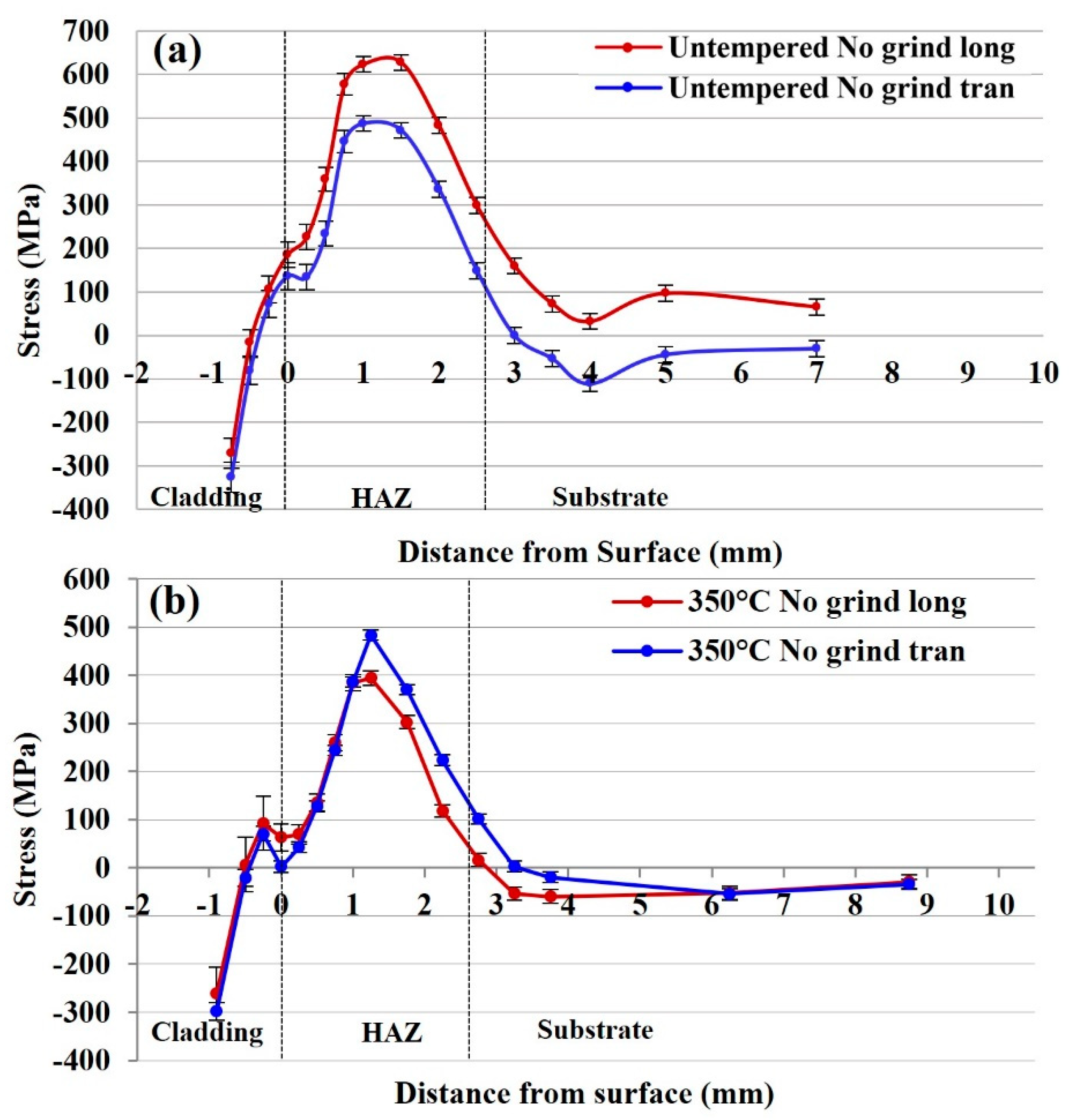
3.2.1. Residual Stress of the Untempered 415SS Laser Clad Rail
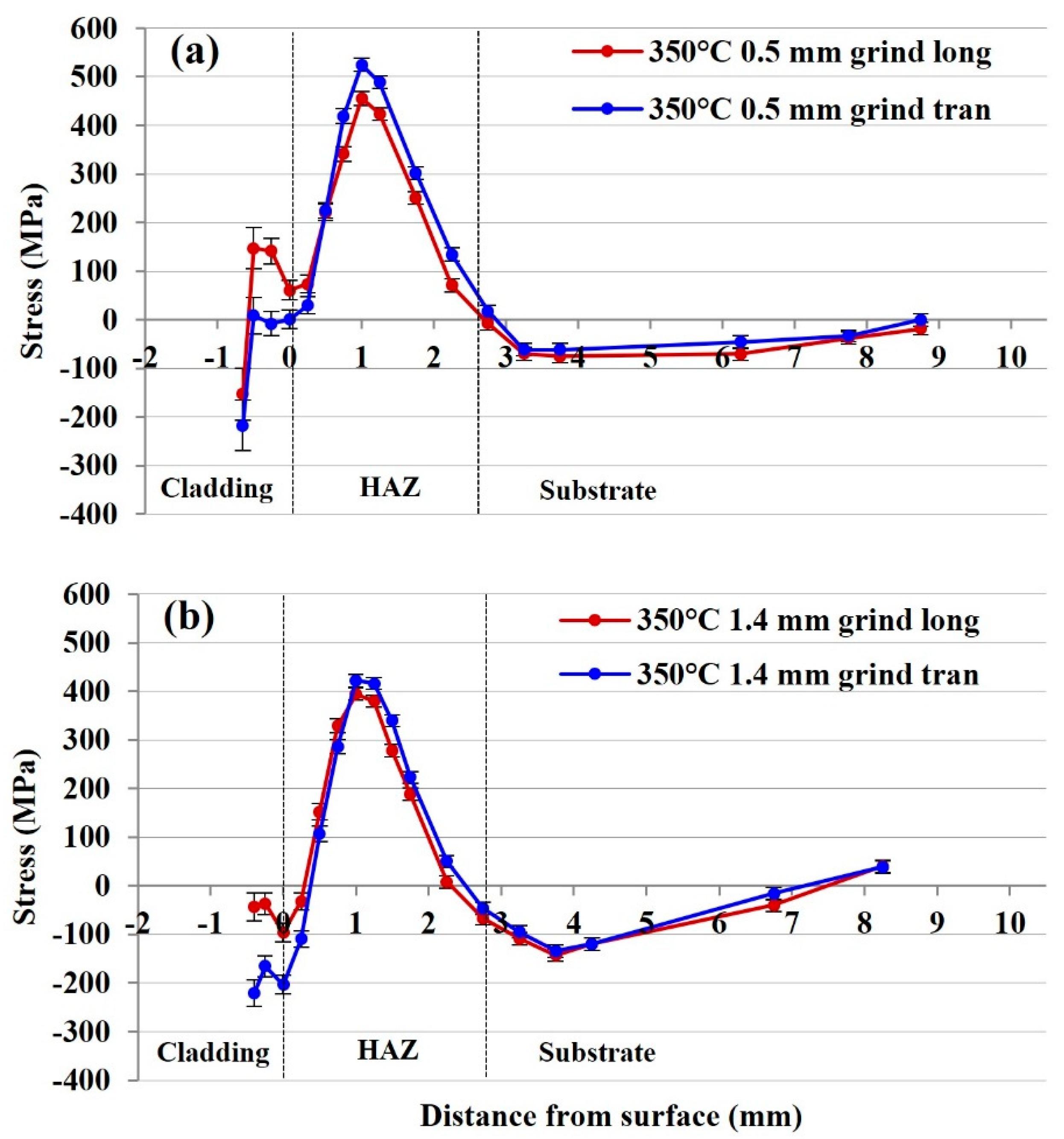
3.2.2. Residual Stresses of 415SS Laser Clad Rail Plates with 350 °C Tempering and Grinding
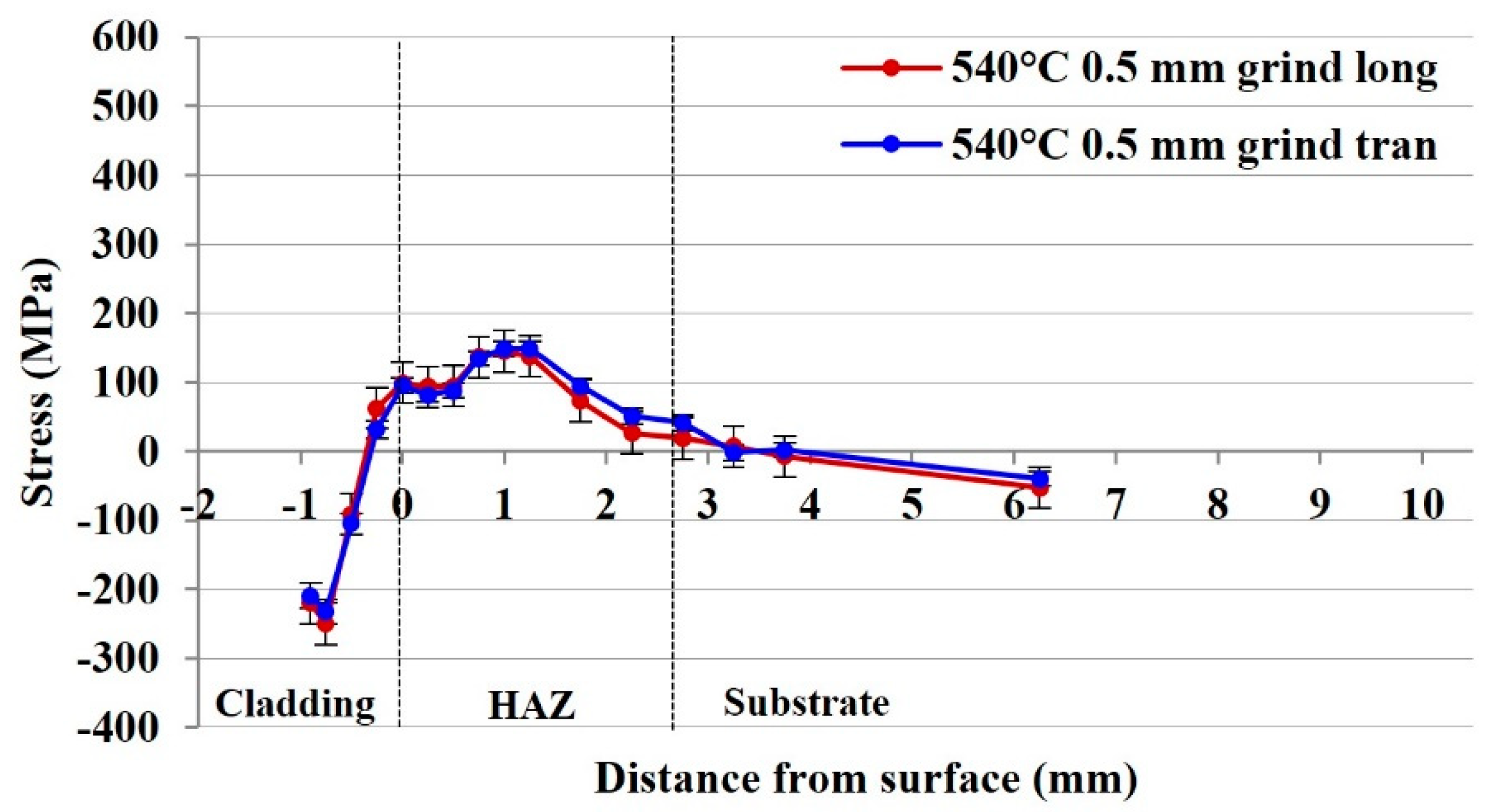
3.2.3. Residual Stress of the 540 °C 415SS Laser Clad Rail with Surface Grinding
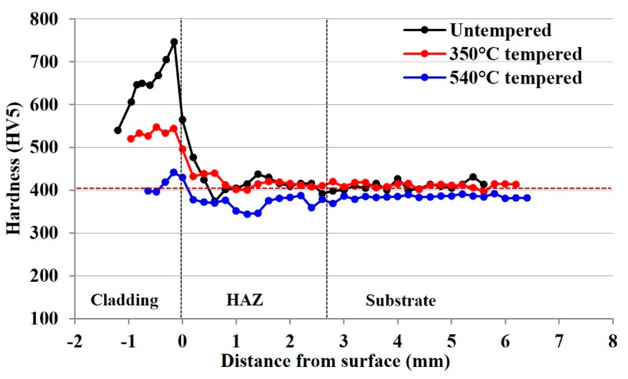
3.3. Influence of Tempering on Microstructural Hardness
3.4. Identification of Microstructural Changes from Neutron Diffraction Data
4. Discussion
4.1. Influence of Tempering on the Residual Stress in the Cladding Layer
4.2. Influence of Tempering on the Residual Stress State in the HAZ
4.3. Influence of Surface Grinding on the Residual Stress State in Cladding and HAZ
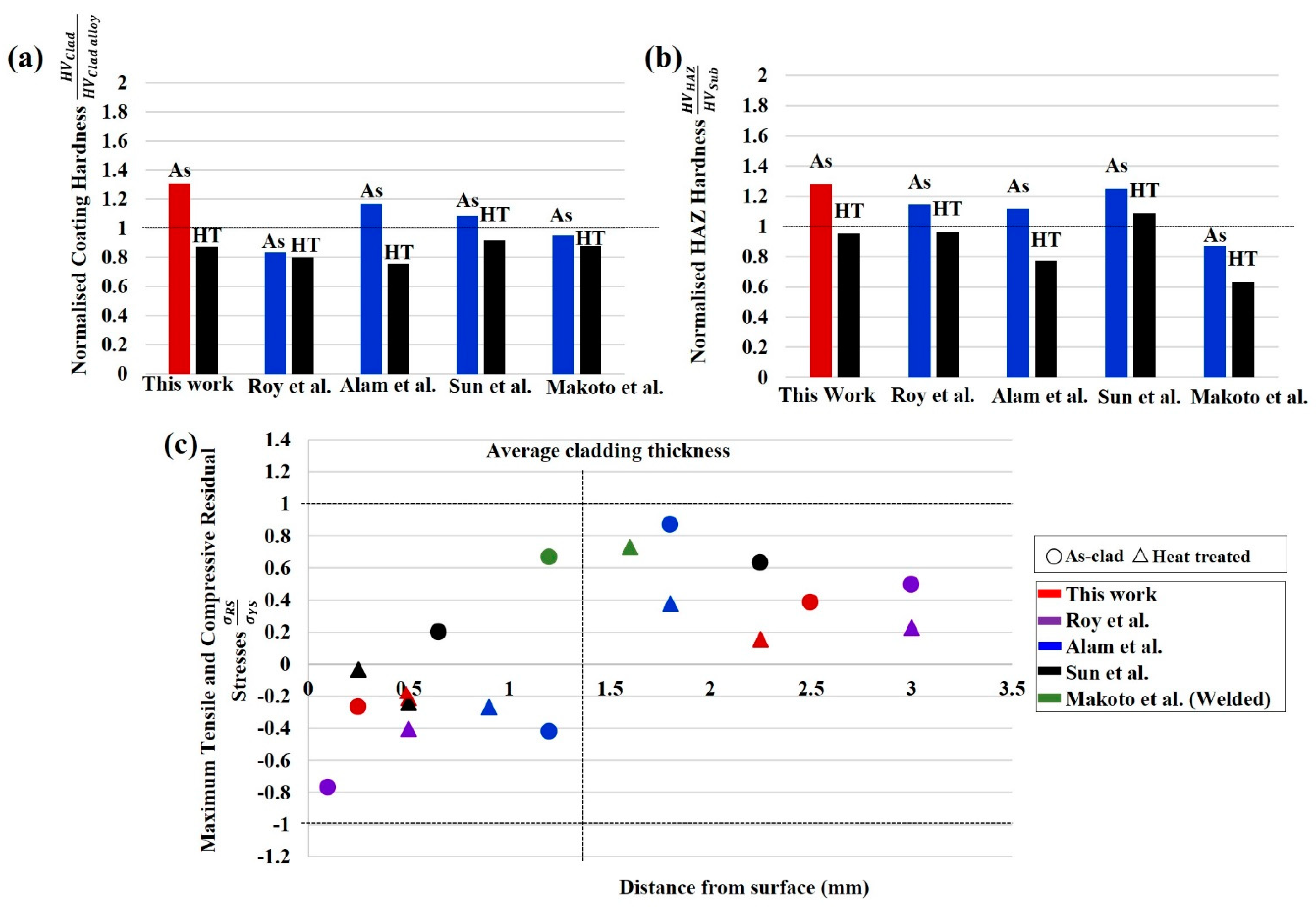
4.4. Comparison of Residual Stress and Hardness Results with Other Studies
5. Conclusions
- In the untempered state, internal stress within the 415SS deposition is compressive in both the transverse and longitudinal directions due to the martensitic microstructure within the cladding layer. The compressive stress is balanced by tensile stress in the HAZ below the cladding–substrate interface produced by thermal inputs and solid-state phase transformations.
- Tempering at 350 °C after cladding maintains the beneficial compressive surface stresses and generates a higher compensating tensile stress in the transverse direction of the HAZ. Grinding after this heat treatment locally relieves the surface stress, with both 0.5 mm and 1.4 mm grinding depths retaining the compressive stress state in the 415SS depositions.
- A post-cladding heat treatment of reheating and holding at 540 °C for 2 h achieves a significant reduction of 76% in tensile stresses in the HAZ when compared to the untempered rail. Removal of 0.5 mm due to grinding also retains the desirable compressive cladding state which may improve the wear and RCF resistance.
- The location of the fusion boundary and significant microstructural changes after cladding and tempering can be identified through correlation of the stress profiles to the FWHM, strain, and intensity data. Therefore, non-destructive neutron diffraction measurements can be used to obtain both residual stress and microstructural information from a metal joint.
Author Contributions
Funding
Institutional Review Board Statement
Informed Consent Statement
Data Availability Statement
Acknowledgments
Conflicts of Interest
References
- Zhang, W.; Zhang, P.; Zhang, J.; Fan, X.; Zhu, M. Probing the effect of abrasive grit size on rail grinding behaviors. J. Manuf. Processes 2020, 53, 388–395. [Google Scholar] [CrossRef]
- Lisiecki, A. Development of laser welding and surface treatment of metals. Materials 2022, 15, 1765. [Google Scholar] [CrossRef] [PubMed]
- Rossini, N.S.; Dassisti, M.; Benyounis, K.Y.; Olabi, A.G. Methods of measuring residual stresses in components. Mater. Des. 2012, 35, 572–588. [Google Scholar] [CrossRef] [Green Version]
- Liu, Y.; Tsang, K.S.; Subramaniam, N.A.; Pang, J.H.L. Structural fatigue investigation of thermite welded rail joints considering weld-induced residual stress and stress relaxation by cyclic load. Eng. Struct. 2021, 235, 112033. [Google Scholar] [CrossRef]
- Kabo, E.; Ekberg, A.; Maglio, M. Rolling contact fatigue assessment of repair rail welds. Wear 2019, 436–437, 203030. [Google Scholar] [CrossRef]
- Lee, S.-H.; Kim, S.; Chang, Y.-S.; Jun, H. Fatigue life assessment of railway rail subjected to welding residual and contact stresses. J. Mech. Sci. Technol. 2014, 28, 4483–4491. [Google Scholar] [CrossRef]
- Guo, H.M.; Wang, Q.; Wang, W.J.; Guo, J.; Liu, Q.Y.; Zhu, M.H. Investigation on wear and damage performance of laser cladding Co-based alloy on single wheel or rail material. Wear 2015, 328–329, 329–337. [Google Scholar] [CrossRef]
- Zhu, Y.; Yang, Y.; Mu, X.; Wang, W.; Yao, Z.; Yang, H. Study on wear and RCF performance of repaired damage railway wheels: Assessing laser cladding to repair local defects on wheels. Wear 2019, 430–431, 126–136. [Google Scholar] [CrossRef]
- Robles Hernández, F.C.; Okonkwo, A.O.; Kadekar, V.; Metz, T.; Badi, N. Laser cladding: The alternative for field thermite welds life extension. Mater. Des 2016, 111, 165–173. [Google Scholar] [CrossRef]
- Tamanna, N.; Rumana Kabir, I.; Naher, S. A numerical investigation of similar and dissimilar clad materials on H13 steel substrate in the Laser Cladding process. Adv. Mater. Process. Technol. 2019, 5, 598–606. [Google Scholar] [CrossRef]
- Nagesha, B.K.; Vinodh, K.; Amit, K.T.; Sanjay, B.; Anand, K.S. Influence of post-processing techniques on residual stresses of SLM processed HPNGV. J. Manuf. Processes 2021, 66, 189–197. [Google Scholar] [CrossRef]
- Chen, J.; Wang, S.-H.; Xue, L. On the development of microstructures and residual stresses during laser cladding and post-heat treatments. J. Mater. Sci. 2012, 47, 779–792. [Google Scholar] [CrossRef]
- Turan, M.E.; Ozcelik, S.; Husem, F.; Ahlatci, H.; Sun, Y.; Tozlu, I. The effect of head hardening process on the residual stress of rails. Proc. Inst. Mech. Eng. Part F J. Rail Rapid Transit 2016, 232, 589–595. [Google Scholar] [CrossRef]
- Ringsberg, J.W.; Skyttebol, A.; Josefson, B.L. Investigation of the rolling contact fatigue resistance of laser cladded twin-disc specimens: FE simulation of laser cladding, grinding and a twin-disc test. Int. J. Fatigue 2005, 27, 702–714. [Google Scholar] [CrossRef]
- Roy, T.; Lai, Q.; Abrahams, R.; Mutton, P.; Paradowska, A.; Soodi, M.; Yan, W. Effect of deposition material and heat treatment on wear and rolling contact fatigue of laser cladded rails. Wear 2018, 412–413, 69–81. [Google Scholar] [CrossRef]
- Roy, T.; Paradowska, A.; Abrahams, R.; Law, M.; Mutton, P.; Soodi, M.; Yan, W. Residual stress in laser cladded heavy-haul rails investigated by neutron diffraction. J. Mater. Process. Technol. 2020, 278, 116511. [Google Scholar] [CrossRef]
- Narayanan, A.; Mostafavi, M.; Pirling, T.; Kabra, S.; Lewis, R.; Pavier, M.J.; Peel, M.J. Residual stress in laser cladded rail. Tribol. Int. 2019, 140, 105844. [Google Scholar] [CrossRef]
- Zhang, Y.; Lan, L.; Shao, G. Influence of strength mismatch on microstructural evolution and mechanical behaviors for Q390/Q690 ferritic steel dissimilar welded joints. Steel Res. Int. 2022, 93, 2100592. [Google Scholar] [CrossRef]
- Nikulin, S.A.; Shitkin, S.L.; Rozhnov, A.B.; Rogachev, S.O.; Nechaykina, T.A. Analysis of the stress state in steel components using portable X-ray diffraction. In Proceedings of the Scientific-Practical Conference “Research and Development-2016”, Cham, Switzerland, 14–15 December 2016; pp. 219–227. [Google Scholar]
- Hutchings, M.T.; Krawitz, A.D. Measurement of Residual and Applied Stress Using Neutron Diffraction, 1st ed.; Hutchings, M.T., Krawitz, A.D., Eds.; Springer: Dordrecht, The Netherlands, 1992. [Google Scholar]
- Alipooramirabad, H.; Paradowska, A.; Nafisi, S.; Reid, M.; Ghomashchi, R. Post-weld heat treatment of API 5L X70 high strength low alloy steel welds. Materials 2020, 13, 5801. [Google Scholar] [CrossRef]
- Lai, Q.; Abrahams, R.; Yan, W.; Qiu, C.; Mutton, P.; Paradowska, A.; Soodi, M.; Wu, X. Influences of depositing materials, processing parameters and heating conditions on material characteristics of laser-cladded hypereutectoid rails. J. Mater. Process. Technol. 2019, 263, 1–20. [Google Scholar] [CrossRef]
- Vashista, M.; Paul, S. Correlation between full width at half maximum (FWHM) of XRD peak with residual stress on ground surfaces. Philos. Mag. 2012, 92, 4194–4204. [Google Scholar] [CrossRef]
- Jun, T.S.; Hofmann, F.; Belnoue, J.; Song, X.; Hofmann, M.; Korsunsky, A.M. Triaxial residual strains in a railway rail measured by neutron diffraction. J. Strain Anal. Eng. Des. 2009, 44, 563–568. [Google Scholar] [CrossRef]
- Kelleher, J.; Prime, M.; Buttle, D.; Mummery, P.; Webster, P.; Shackleton, J.; Withers, P. The measurement of residual stress in railway rails by diffraction and other methods. J. Neutron Res. 2003, 11, 187–193. [Google Scholar] [CrossRef]
- Fu, P.; Chu, R.; Xu, Z.; Ding, G.; Jiang, C. Relation of hardness with FWHM and residual stress of GCr15 steel after shot peening. Appl. Surf. Sci. 2018, 431, 165–169. [Google Scholar] [CrossRef]
- Filippone, R.; Root, J.; Jacques, P.; Yue, S. The influence of martensite on line broadening in neutron diffraction spectra of a DP steel. ISIJ Int. 2002, 42, 304–309. [Google Scholar] [CrossRef] [Green Version]
- Tomota, Y. Crystallographic characterization of steel microstructure using neutron diffraction. Sci. Technol. Adv. Mater. 2019, 20, 1189–1206. [Google Scholar] [CrossRef] [Green Version]
- Jiang, W.; Chen, W.; Woo, W.; Tu, S.-T.; Zhang, X.-C.; Em, V. Effects of low-temperature transformation and transformation-induced plasticity on weld residual stresses: Numerical study and neutron diffraction measurement. Mater. Des. 2018, 147, 65–79. [Google Scholar] [CrossRef]
- Wang, X.; Hu, L.; Xu, Q.; Chen, D.-X.; Sun, S.-T. Influence of martensitic transformation on welding residual stress in plates and pipes. Sci. Technol. Weld. Join. 2017, 22, 505–511. [Google Scholar] [CrossRef]
- Jun, H.-K.; Seo, J.-W.; Jeon, I.-S.; Lee, S.-H.; Chang, Y.-S. Fracture and fatigue crack growth analyses on a weld-repaired railway rail. Eng. Fail. Anal. 2016, 59, 478–492. [Google Scholar] [CrossRef]
- Alam, M.K.; Edrisy, A.; Urbanic, J.; Pineault, J. Microhardness and stress analysis of laser-cladded AISI 420 martensitic stainless steel. J. Mater. Eng. Perform. 2017, 26, 1076–1084. [Google Scholar] [CrossRef]
- Lippold, J.C. Welding Metallurgy and Weldability of Stainless Steel; Wiley: Hoboken, NJ, USA, 2014. [Google Scholar]
- Kelleher, J.F.; Buttle, D.J.; Mummery, P.M.; Withers, P.J. Residual stress mapping in railway rails. Mater. Sci. Forum 2005, 490–491, 165–170. [Google Scholar] [CrossRef]
- Ishigami, A.; Roy, M.J.; Walsh, J.N.; Withers, P.J. The effect of the weld fusion zone shape on residual stress in submerged arc welding. Int. J. Adv. Manuf. Technol. 2017, 90, 3451–3464. [Google Scholar] [CrossRef]
- Pandey, C.; Mahapatra, M.M.; Kumar, P.; Saini, N. Some studies on P91 steel and their weldments. J. Alloys Compd. 2018, 743, 332–364. [Google Scholar] [CrossRef]
- Iyota, M.; Mikami, Y.; Hashimoto, T.; Taniguchi, K.; Ikeda, R.; Mochizuki, M. The effect of martensitic transformation on residual stress in resistance spot welded high-strength steel sheets. J. Alloys Compd. 2013, 577, S684–S689. [Google Scholar] [CrossRef]
- Harisha, S.R.; Sharma, S.; Kini, A.U.; Gurumurty, B.M.; Hegde, A. Micro-hardness variation of micro-phases during spheroidisation of AISI4340 steel. Cogent Eng. 2021, 8, 1875536. [Google Scholar] [CrossRef]
- Sun, S.D.; Liu, Q.; Brandt, M.; Luzin, V.; Cottam, R.; Janardhana, M.; Clark, G. Effect of laser clad repair on the fatigue behaviour of ultra-high strength AISI 4340 steel. Mater. Sci. Eng. A 2014, 606, 46–57. [Google Scholar] [CrossRef]
- Makoto, U.; Jinya, K.; Hiroyuki, N.; Kunio, O. Evaluation of residual stress near the weld overlay cladding by welding and post-weld heat treatment. Weld. Int. 2014, 28, 521–534. [Google Scholar] [CrossRef]


| Alloy | Fe | Cr | C | Mn | Si | Ni | Cu | Mo | V | Nb | Al | S | P | Ti |
|---|---|---|---|---|---|---|---|---|---|---|---|---|---|---|
| 415SS | Bal | 12.4 | 0.13 | 0.85 | 0.48 | 0.21 | 0.04 | 0.03 | 0.01 | <0.01 | <0.01 | 0.01 | 0.02 | <0.01 |
| Rail | Bal | 0.20 | 0.93 | 0.95 | 0.28 | <0.01 | - | <0.01 | <0.01 | <0.01 | <0.01 | 0.014 | - | - |
| Sample | Cladding | Tempering Process | Surface Grinding |
|---|---|---|---|
| Rail (600 mm section with 400 mm cladding) | 415SS single layer | untempered | No grinding |
| Plate (60 × 50 × 11 mm3) | 415SS single layer | 350 °C and slow cooling | No grinding |
| Plate (60 × 50 × 11 mm3) | 415SS single layer | 350 °C and slow cooling | 0.5 mm removed |
| Plate (60 × 50 × 11 mm3) | 415SS single layer | 350 °C and slow cooling | 1.4 mm removed |
| Plate (60 × 50 × 11 mm3) | 415SS single layer | 540 °C for 2 h, air cooling | 0.5 mm removed |
Publisher’s Note: MDPI stays neutral with regard to jurisdictional claims in published maps and institutional affiliations. |
© 2022 by the authors. Licensee MDPI, Basel, Switzerland. This article is an open access article distributed under the terms and conditions of the Creative Commons Attribution (CC BY) license (https://creativecommons.org/licenses/by/4.0/).
Share and Cite
Kendall, O.; Fasihi, P.; Abrahams, R.; Paradowska, A.; Reid, M.; Lai, Q.; Qiu, C.; Mutton, P.; Soodi, M.; Yan, W. Application of a New Alloy and Post Processing Procedures for Laser Cladding Repairs on Hypereutectoid Rail Components. Materials 2022, 15, 5447. https://doi.org/10.3390/ma15155447
Kendall O, Fasihi P, Abrahams R, Paradowska A, Reid M, Lai Q, Qiu C, Mutton P, Soodi M, Yan W. Application of a New Alloy and Post Processing Procedures for Laser Cladding Repairs on Hypereutectoid Rail Components. Materials. 2022; 15(15):5447. https://doi.org/10.3390/ma15155447
Chicago/Turabian StyleKendall, Olivia, Panahsadat Fasihi, Ralph Abrahams, Anna Paradowska, Mark Reid, Quan Lai, Cong Qiu, Peter Mutton, Mehdi Soodi, and Wenyi Yan. 2022. "Application of a New Alloy and Post Processing Procedures for Laser Cladding Repairs on Hypereutectoid Rail Components" Materials 15, no. 15: 5447. https://doi.org/10.3390/ma15155447