
Uniaxial Compressive Stress–Strain Relation of Recycled Coarse Aggregate Concrete with Different Carbonation Depths


Abstract
:Highlights
- Uniaxial compressive stress–strain curves of recycled aggregate concrete (RAC) with different carbonation depth were investigated.
- The effect of carbonation depth on peak stress, strain, elastic modulus, and the relative toughness of RAC was studied.
- Stress–strain models of recycled aggregate concrete with different carbonation depths were established.
Abstract
1. Introduction
2. Experimental Method
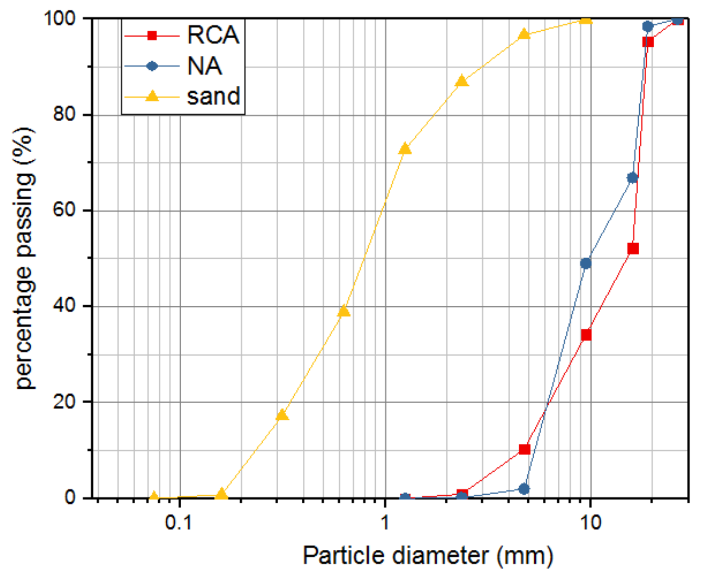
2.1. Materials and Mixture Proportions
2.2. Accelerated Carbonation Procedure
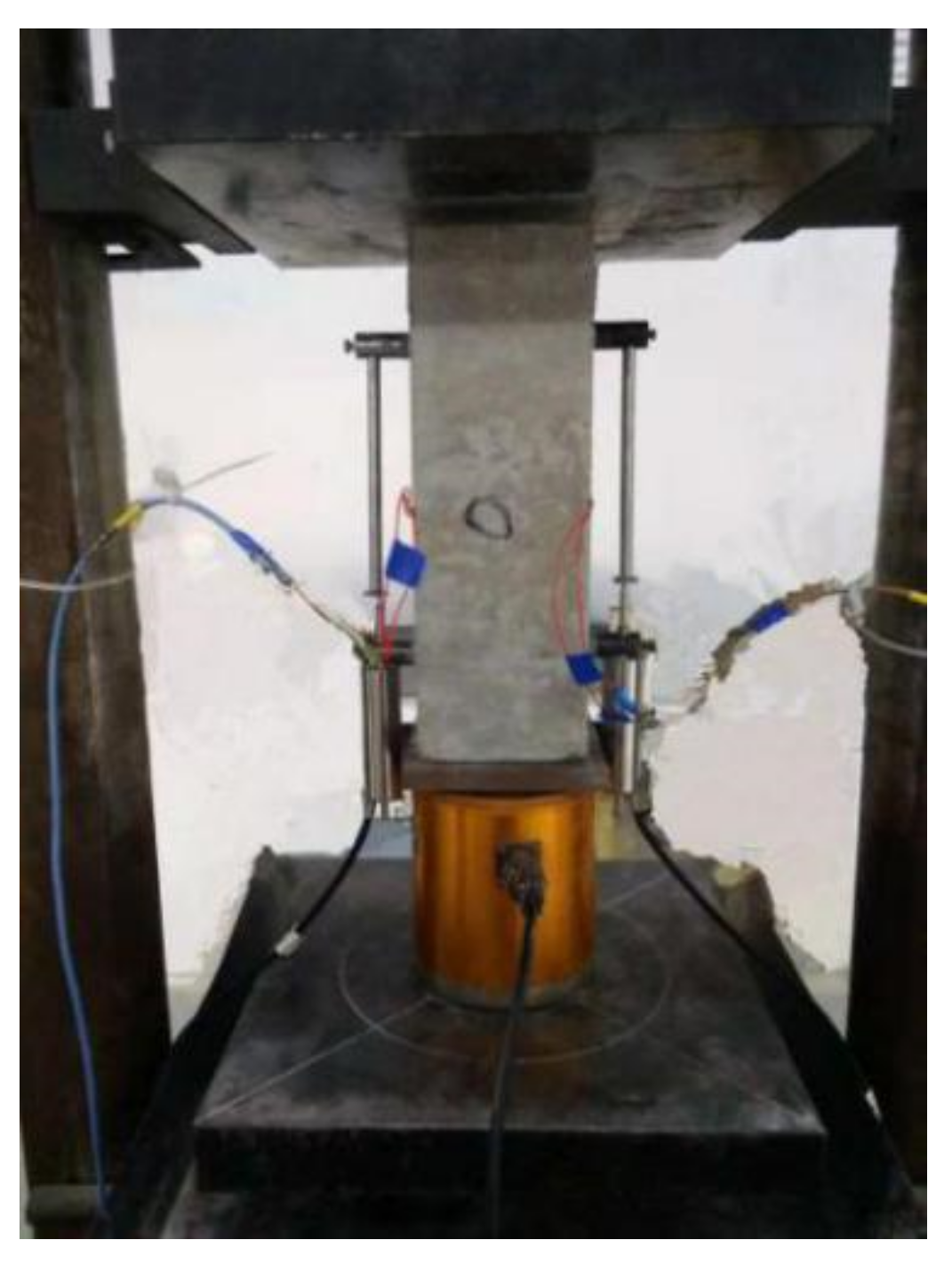
2.3. Uniaxial Compressive Loading Test
3. Experimental Results and Discussion
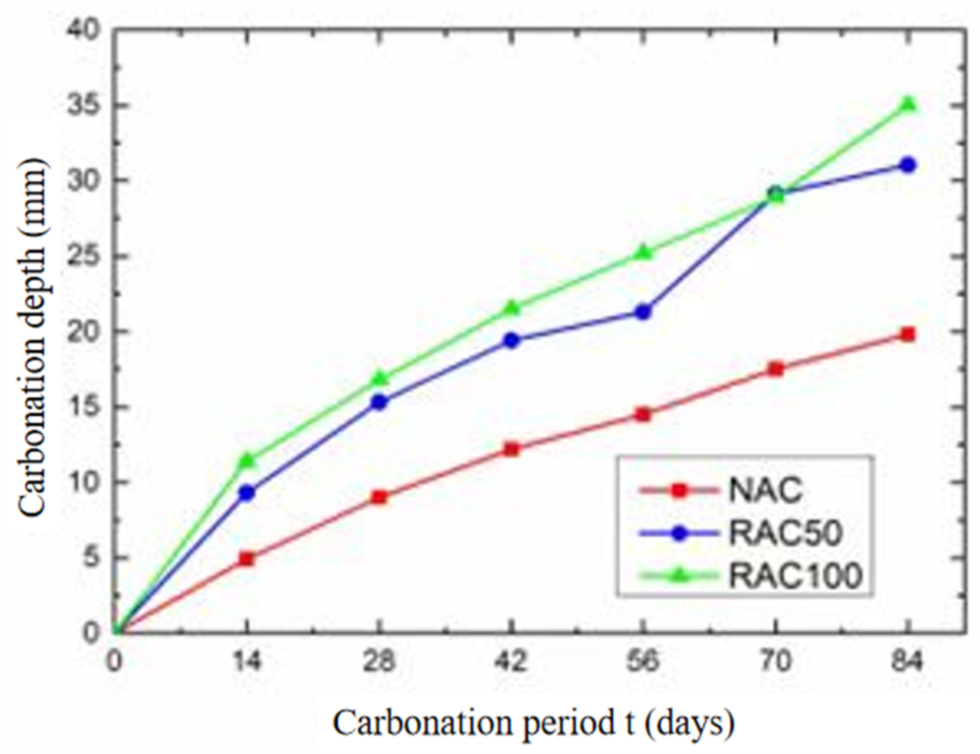
3.1. Carbonation Depth
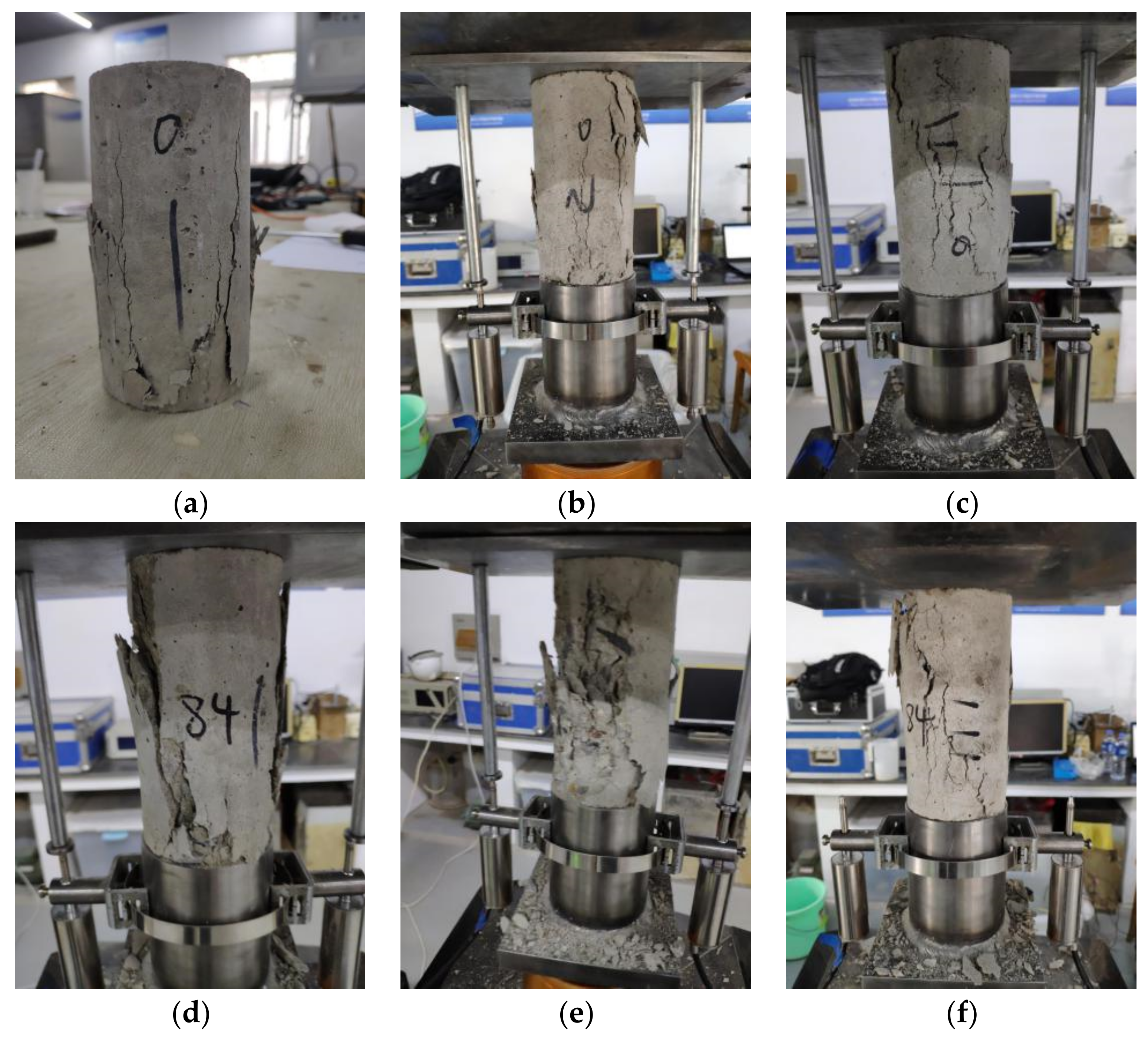
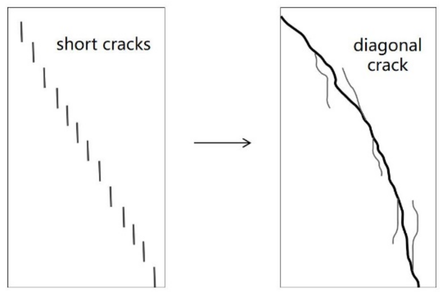
3.2. Failure Pattern
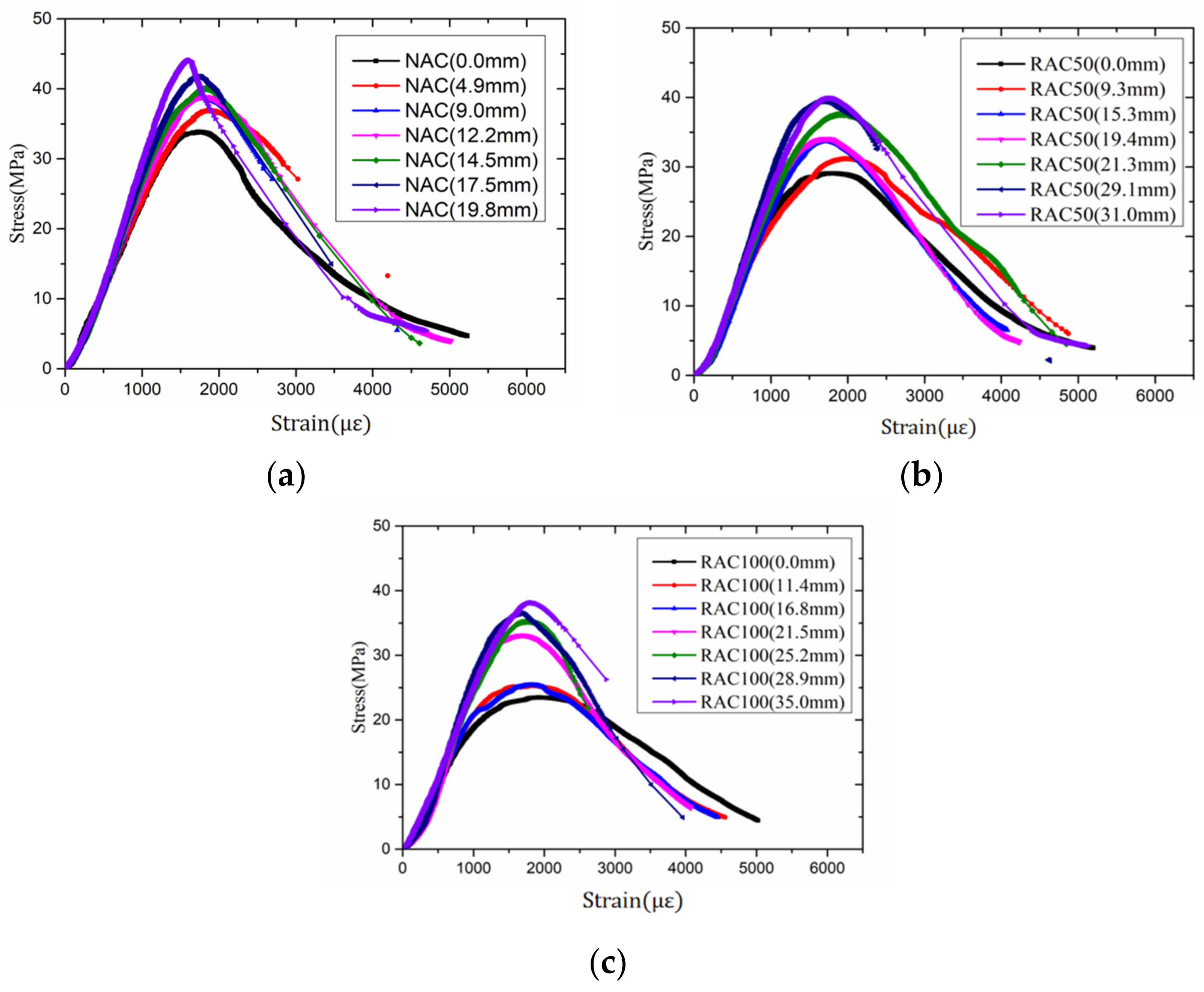
3.3. Uniaxial Compressive Stress–Strain Curves
3.3.1. Peak Stress
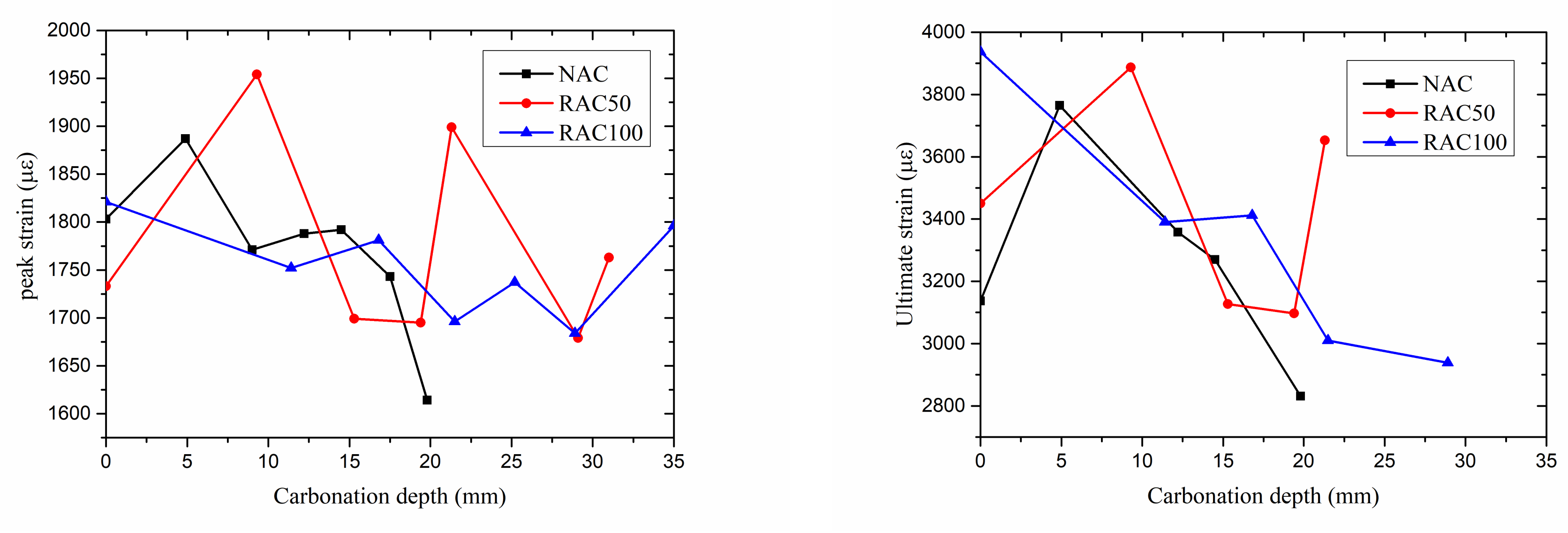
3.3.2. Strain
3.3.3. Elastic Modulus
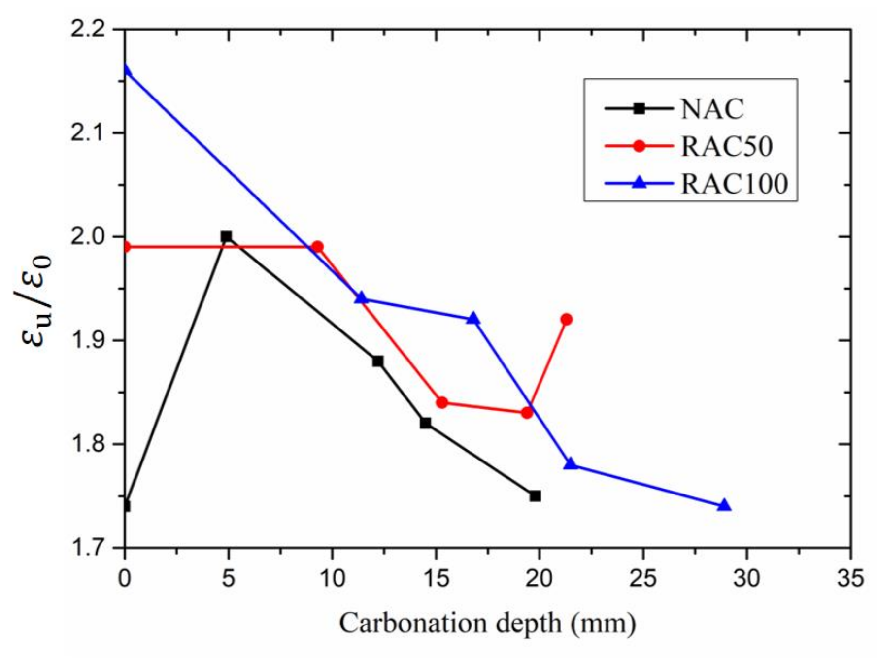
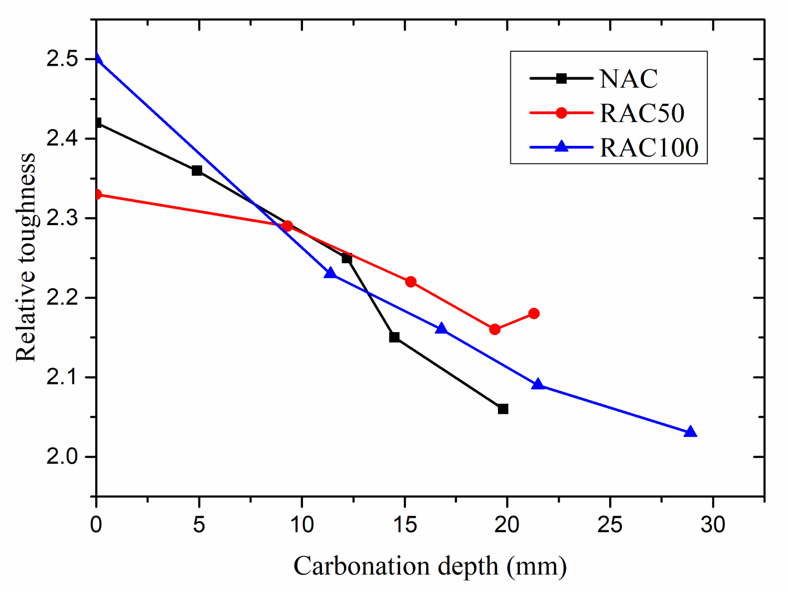
3.3.4. Relative Toughness
4. Stress–Strain Relation of Carbonated RAC and NAC
5. Summary
- (1)
- During the accelerated carbonation, the values of the carbonation depth of RAC increases as the replacement ratio of recycled coarse aggregate increases. At 84 days, RAC100 was fully carbonated and the carbonation depth was 35.0 mm, whereas that of RAC50 and NAC were 31.0 and 19.2 mm, respectively.
- (2)
- The peak stress and elastic modulus of RAC and NAC specimens increased with the increase of carbonation depth, and the peak stress of fully carbonated RAC100 increased by about 62.8% and elastic modulus has increased by about 28.3%. The ratio of ultimate strain to peak strain and relative toughness of RAC and NAC specimens decreased overall with the increase of carbonation depth. When the carbonation depth reached about 20 mm, the relative toughness of RAC50 and RAC100 specimens decreased by about 7.1% and 16.2%, respectively, compared with non-carbonated specimens.
- (3)
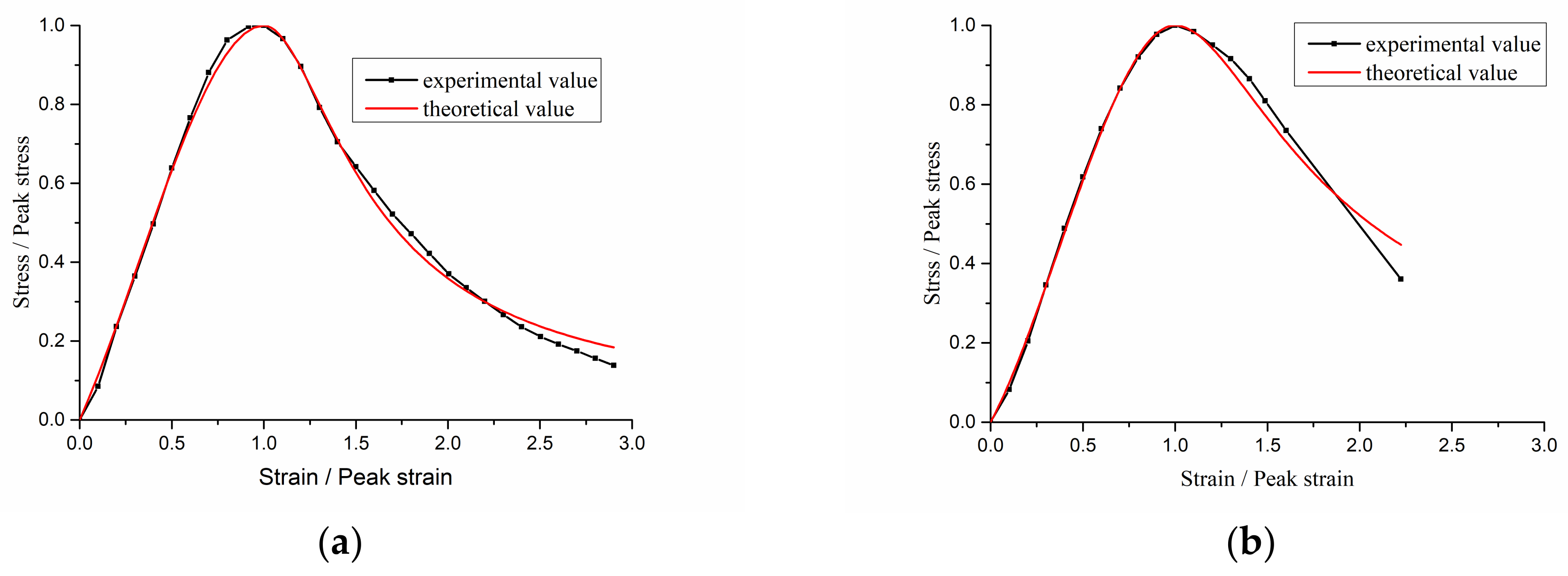
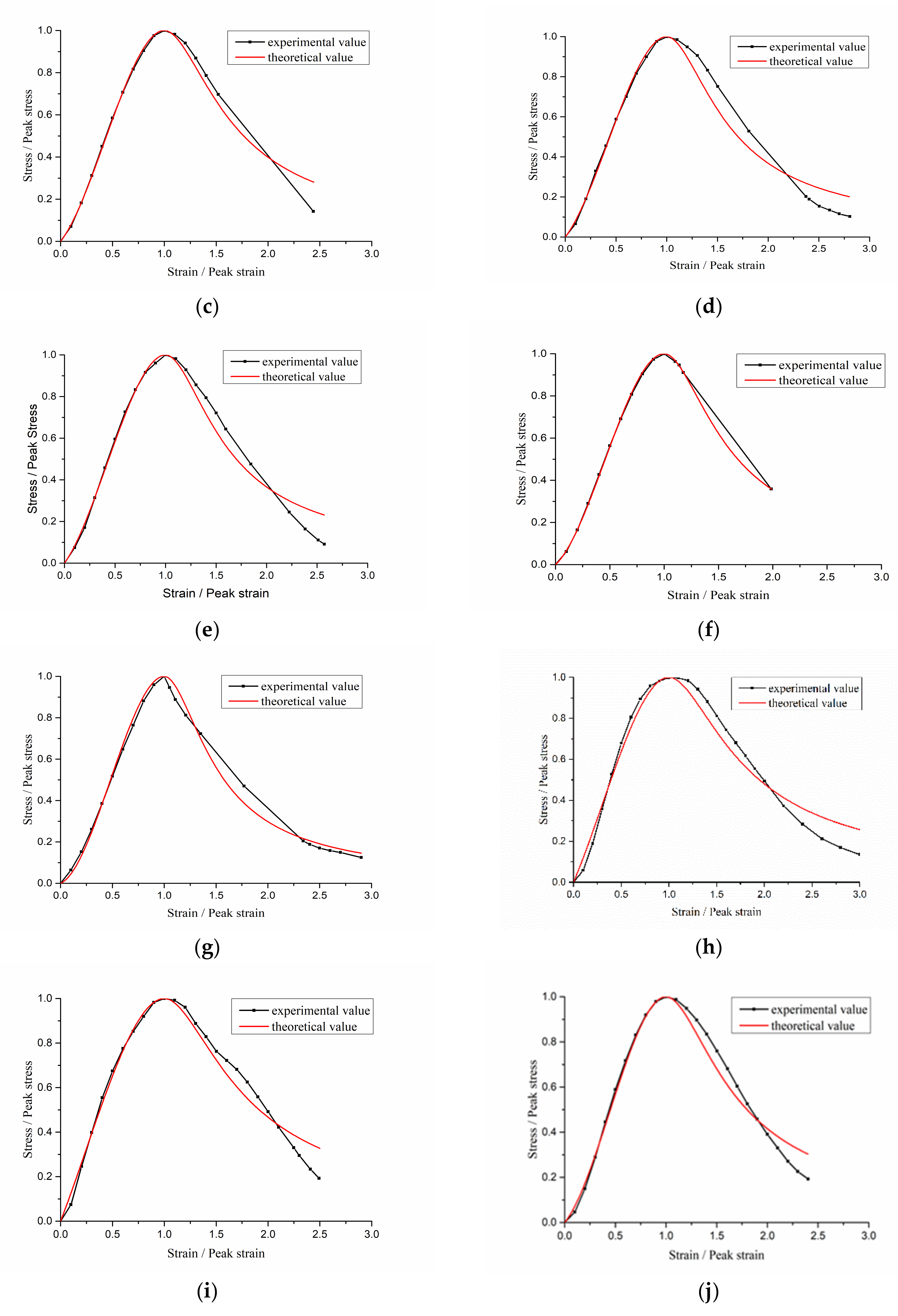
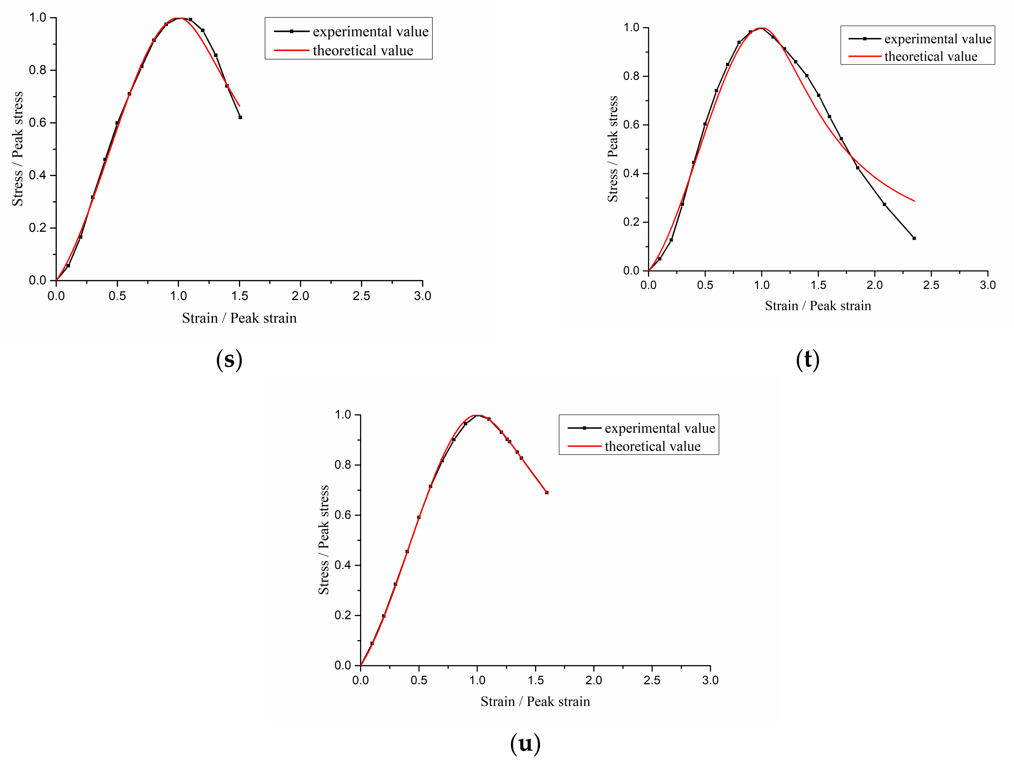
- Stress–strain models of recycled aggregate concrete with different carbonation depths were established, and the experimental values are in good agreement with the theoretical values and correlation coefficients are over 0.9. Carbonation decreased the relative slope of the ascending part and increased the relative steepness of the descending part of stress–strain curves of recycled aggregate concrete.
Author Contributions
Funding
Acknowledgments
Conflicts of Interest
References
- Vieira, C.S.; Pereira, P.M. Use of recycled construction and demolition materials in geotechnical applications: A review. Resour. Conserv. Recycl. 2015, 103, 192–204. [Google Scholar] [CrossRef]
- Zhang, J.H.; Ding, L.; Li, F.; Peng, J.H. Recycled aggregates from construction and demolition wastes as alternative filling materials for highway subgrades in China. J. Clean. Prod. 2020, 225, 120–223. [Google Scholar] [CrossRef]
- Fonseca, N.; de Brito, J.; Evangelista, L. The influence of curing conditions on the mechanical performance of concrete made with recycled concrete waste. Cem. Concr. Compos. 2011, 33, 637–643. [Google Scholar] [CrossRef]
- Rao, M.C.; Bhattacharyya, S.K.; Barai, S.V. Influence of field recycled coarse aggregate on properties of concrete. Mater. Struct. 2011, 44, 205–220. [Google Scholar] [CrossRef]
- Xiao, J.Z.; Li, W.G.; Fan, Y.H.; Huang, X. An overview of study on recycled aggregate concrete in China (1996–2011). Constr. Build. Mater. 2012, 31, 364–383. [Google Scholar] [CrossRef]
- Lima, C.; Caggiano, A.; Faella, C.; Martinelli, E.; Pepe, M.; Realfonzo, R. Physical properties and mechanical behaviour of concrete made with recycled aggregates and fly ash. Constr. Build. Mater. 2013, 47, 547–559. [Google Scholar] [CrossRef]
- Kou, S.C.; Poon, C.S. Enhancing the durability properties of concrete prepared with coarse recycled aggregate. Constr. Build. Mater. 2012, 35, 69–76. [Google Scholar] [CrossRef]
- Topc, L.B.; Sengel, S. Properties of concretes produced with waste concrete aggregate. Cem. Concr. Res. 2004, 34, 1307–1312. [Google Scholar] [CrossRef]
- Azevedo, A.R.G.; Cecchin, D.; Carmo, D.F.; Silva, F.; Campos, C.; Shtrucka, T.; Marvila, M.; Monteiro, S. Analysis of the compactness and properties of the hardened state of mortars with recycling of construction and demolition waste (CDW). J. Mater. Res. Technol. 2020, 9, 5942–5952. [Google Scholar] [CrossRef]
- Barbudo, A.; Agrela, F.; Ayuso, J.; Jiménez, J.R.; Poon, C.S. Statistical analysis of recycled aggregates derived from different sources for sub-base applications. Constr. Build. Mater. 2012, 28, 28–129. [Google Scholar] [CrossRef]
- Tam, V.W.Y.; Gao, X.F.; Tam, C.M. Microstructural analysis of recycled aggregate concrete produced from two-stage mixing approach. Cem. Concr. Res. 2005, 35, 1195–1203. [Google Scholar] [CrossRef] [Green Version]
- Sagoe-Crentsil, K.K.; Brown, T.; Taylor, A.H. Performance of concrete made with commercially produced coarse recycled concrete aggregate. Cem. Concr. Res. 2001, 31, 707–712. [Google Scholar] [CrossRef]
- Cui, Z.L.; Yang, L.H.; Ohaga, Y. Durability test investigation on the recycled aggregate concrete. Bull. Chin. Ceram. Soc. 2007, 26, 1107–1111. [Google Scholar] [CrossRef]
- Zeng, X.C. Progress in the research of carbonation resistance of RAC. Constr. Build. Mater. 2020, 230, 116976. [Google Scholar] [CrossRef]
- Lu, W.S.; Tam, V.W.Y. Construction waste management policies and their effectiveness in Hong Kong: A longitudinal review. Renew. Sustain. Energy Rev. 2013, 23, 214–223. [Google Scholar] [CrossRef] [Green Version]
- Omrane, M.; Kenai, S.; Kadri, E.H.; Abdelkarim, A.M. Performance and durability of self compacting concrete using recycled concrete aggregates and natural pozzolan. J. Clean. Prod. 2017, 165, 415–430. [Google Scholar] [CrossRef]
- Xie, J.H.; Fang, C.; Lu, Z.H.; Li, Z.J.; Li, L.J. Effects of the addition of silica fume and rubber particles on the compressive behaviour of recycled aggregate concrete with steel fibres. J. Clean. Prod. 2018, 197, 656–667. [Google Scholar] [CrossRef]
- Ahmed, T.W.; Mohammed Ali, A.A.; Zidan, R.S. Properties of high strength polypropylene fiber concrete containing recycled aggregate. Constr. Build. Mater. 2020, 241, 118010. [Google Scholar] [CrossRef]
- Hanumesh, B.M.; Harish, B.A.; Ramana, N.V. Influence of Polypropylene Fibres on Recycled Aggregate Concrete. Mater. Today Proc. 2018, 5, 1147–1155. [Google Scholar] [CrossRef]
- Zhu, Y.G.; Kou, S.C.; Poon, C.S.; Dai, J.G.; Li, Q.Y. Influence of silane-based water repellent on the durability properties of recycled aggregate concrete. Cem. Concr. Compos. 2013, 35, 32–38. [Google Scholar] [CrossRef]
- Vivian, W.Y.; Tam, A.B.; Khoa, N.L.; Li, W.G. Utilising CO2 technologies for recycled aggregate concrete: A critical review. Constr. Build. Mater. 2020, 250, 118903. [Google Scholar] [CrossRef]
- Zhang, J.K.; Shi, C.J.; Li, Y.K.; Pan, X.Y.; Poon, C.S.; Xie, Z.B. Influence of carbonated recycled concrete aggregate on properties of cement mortar. Constr. Build. Mater. 2015, 98, 1–7. [Google Scholar] [CrossRef]
- Zhan, B.J.; Poon, C.S.; Liu, Q.; Kou, S.; Shi, C.J. Experimental study on CO2 curing for enhancement of recycled aggregate properties. Constr. Build. Mater. 2014, 67, 3–7. [Google Scholar] [CrossRef]
- Zhan, B.J.; Poon, C.; Shi, C.J. CO2 curing for improving the properties of concrete blocks containing recycled aggregates. Cem. Concr. Compos. 2013, 42, 1–8. [Google Scholar] [CrossRef]
- Zhan, B.J.; Xuan, D.X.; Poon, C.S.; Shi, C.J. Effect of curing parameters on CO2 curing of concrete blocks containing recycled aggregates. Cem. Concr. Compos. 2016, 71, 122–130. [Google Scholar] [CrossRef]
- Xuan, D.X.; Zhan, B.J.; Poon, C.S. A maturity approach to estimate compressive strength development of CO2-cured concrete blocks. Cem. Concr. Compos. 2018, 85, 153–160. [Google Scholar] [CrossRef]
- Xiao, J.Z.; Zhang, K.J.; Akbarnezhad, A. Variability of stress-strain relationship for recycled aggregate concrete under uniaxial compression loading. J. Clean. Prod. 2018, 181, 753–771. [Google Scholar] [CrossRef]
- Bairagi, N.K.; Ravande, K.; Pareek, V.K. Behaviour of concrete with different proportions of natural and recycled aggregates. Resour. Conserv. Recycl. 1993, 9, 109–126. [Google Scholar] [CrossRef]
- Xiao, J.Z.; Li, J.B.; Zhang, C. Mechanical properties of recycled aggregate concrete under uniaxial loading. Cem. Concr. Res. 2005, 35, 1187–1194. [Google Scholar] [CrossRef]
- Xiao, J.Z.; Du, J.T. Complete stress-strain curve of concrete with different recycled coarse aggregates under uniaxial compression. J. Build. Mater. 2008, 11, 111–115. (In Chinese) [Google Scholar]
- Wu, J.; Jing, X.H.; Wang, Z. Uni-axial compressive stress-strain relation of recycled coarse aggregate concrete after freezing and thawing cycles. Constr. Build. Mater. 2017, 134, 210–219. [Google Scholar] [CrossRef]
- Luo, S.; Ye, S.C.; Xiao, J.Z.; Zheng, J.L.; Zhu, Y.T. Carbonated recycled coarse aggregate and uniaxial compressive stress-strain relation of recycled aggregate concrete. Constr. Build. Mater. 2018, 188, 956–965. [Google Scholar] [CrossRef]
- Sormeh, K.H.; Shao, Y.X.; Ghoshal, S. Mathematical modeling of CO2 uptake by concrete during accelerated carbonation curing. Cem. Concr. Res. 2015, 67, 1–10. [Google Scholar] [CrossRef]
- Lee, H.S.; Wang, X.Y. Evaluation of compressive strength development and carbonation depth of high volume slag-blended concrete. Constr. Build. Mater. 2016, 124, 45–54. [Google Scholar] [CrossRef]
- Thomas, C.; Setién, J.; Polanco, J.A.; Alaejos, P.; Sánchez de Juan, M. Durability of recycled aggregate concrete. Constr. Build. Mater. 2013, 40, 1054–1065. [Google Scholar] [CrossRef]
- Bravo, M.; Brito, J.D.; Pontes, J.; Evangelista, L. Durability performance of concrete with recycled aggregates from construction and demolition waste plants. Constr. Build. Mater. 2015, 77, 357–369. [Google Scholar] [CrossRef]
- Yang, H.F.; Deng, Z.H.; Li, X.L. Microscopic mechanism study on carbonation resistance of recycled aggregate concrete. Adv. Mater. Res. 2011, 194–196, 1001–1006. [Google Scholar] [CrossRef]
- Chen, T.W.; Wu, J.; Dong, G.Q. Mechanical properties and uniaxial compression stress-strain relation of recycled coarse aggregate concrete after carbonation. Materials 2021, 14, 2215. [Google Scholar] [CrossRef]
- Morandeau, A.; Thiéry, M.; Dangla, P. Investigation of the carbonation mechanism of CH and C-S-H in terms of kinetics, microstructure changes and moisture properties. Cem. Concr. Res. 2014, 56, 153–170. [Google Scholar] [CrossRef] [Green Version]
- Della, M.R.; George, R.G. Porosity-Strength Relation in Cementitious Materials with Very High Strengths. J. Am. Ceram. Soc. 1973, 56, 549–550. [Google Scholar] [CrossRef]
- Powers, T.C. Structure and Physical Properties of Hardened Portland Cement Paste. J. Am. Ceram. Soc. 1958, 41, 1–6. [Google Scholar] [CrossRef]
- Khan, M.I.; Lynsdale, C.J.; Waldron, P. Porosity and strength of PFA/SF/OPC ternary blended paste. Cem. Concr. Res. 2000, 30, 1225–1229. [Google Scholar] [CrossRef]
- Li, L.; Poon, C.S.; Xiao, J.Z.; Xuan, D.X. Effect of carbonated recycled coarse aggregate on the dynamic compressive behavior of recycled aggregate concrete. Constr. Build. Mater. 2017, 151, 52–62. [Google Scholar] [CrossRef]
- Xiao, J.Z.; Li, W.G.; Sun, Z.H.; David, A.; Lange, S.P.S. Properties of interfacial transition zones in recycled aggregate concrete tested by nanoindentation. Cem. Concr. Compos. 2013, 37, 276–292. [Google Scholar] [CrossRef]
- Shaikh, F.U.A. Mechanical and durability properties of fly ash geopolymer concrete containing recycled coarse aggregates. Int. J. Sustain. Built Environ. 2016, 5, 277–287. [Google Scholar] [CrossRef] [Green Version]
- Çopuroğlu, O.; Schlangen, E. Modeling of frost salt scaling. Cem. Concr. Res. 2008, 38, 27–39. [Google Scholar] [CrossRef]
- De Han, J.; Pan, G.H.; Sun, W.; Wang, C.H.; Cui, D. Application of nanoindentation to investigate chemomechanical properties change of cement paste in the carbonation reaction. Sci. China. Technol. Sci. 2012, 55, 616–622. [Google Scholar] [CrossRef]
- Zhao, S.J.; Fan, J.J.; Sun, W. Utilization of iron ore tailings as fine aggregate in ultra-high performance concrete. Constr. Build. Mater. 2014, 50, 540–548. [Google Scholar] [CrossRef]
- Dong, S.F.; Han, B.G.; Yu, X.; Ou, J.P. Dynamic impact behaviors and constitutive model of super-fine stainless wire reinforced reactive powder concrete. Constr. Build. Mater. 2018, 184, 602–616. [Google Scholar] [CrossRef]
- Wu, Z.M.; Shi, C.J.; He, W.; Wang, D.H. Uniaxial compression behavior of ultra-high performance concrete with hybrid steel fiber. J. Mater. Civ. Eng. 2016, 28, 06016017. [Google Scholar] [CrossRef]
- Jiang, J.Y.; Feng, T.T.; Chu, H.Y.; Wu, Y.R.; Wang, F.J.; Zhou, W.J.; Wang, Z.F. Quasi-static and dynamic mechanical properties of eco-friendly ultra-high-performance concrete containing aeolian sand. Cem. Concr. Compos. 2019, 97, 369–378. [Google Scholar] [CrossRef]
- Guo, Z. Strength and Constitutive Relations of Concrete—Principle and Application; China Construction Industry Press: Beijing, China, 2004; pp. 42–44. (In Chinese) [Google Scholar]
- Bai, L.L. Experimental Study on Compressive Strength and Microscopic Properties of Recycled Concrete with Reinforced Coarse Aggregate; Xi’an University of Architecture and Technology: Xi’an, China, 2019; pp. 58–59. (In Chinese) [Google Scholar]


| Property | Value |
|---|---|
| Type and class | P.O 42.5 |
| Specific surface area (m2 kg−1) | 335 |
| Initial and final setting times (min) | 215/265 |
| 28-day compressive and flexural strength (MPa) | 49.8/8.7 |
| SO3 (%) | 2.4 |
| MgO (%) | 1.8 |
| CaO (%) | 62.6 |
| SiO2 (%) | 21.2 |
| Al2O3 (%) | 5.6 |
| Fe2O3 (%) | 4.6 |
| Aggregate Type | Coarse Aggregate Grading (mm) | Apparent Density (kg/m3) | Water Absorption (%) | Crushing Value (%) |
|---|---|---|---|---|
| NCA | 5–20 | 2773 | 1.08 | 3.2 |
| RCA | 5–20 | 2541 | 5.12 | 14.2 |
| Concrete Type | Water (kg/m3) | Cement (kg/m3) | Water to Cement Ratio | NCA (kg/m3) | RCA (kg/m3) | Fine Aggregates (kg/m3) |
|---|---|---|---|---|---|---|
| NAC | 195 | 274.6 | 0.71 | 1131.1 | 0.0 | 754.1 |
| RAC50 | 200 | 333.3 | 0.60 | 566.8 | 519.0 | 694.2 |
| RAC100 | 205 | 410.0 | 0.50 | 0.0 | 1006.6 | 643.5 |
| Specimens | Coefficient a | Correlation Coefficient | Coefficient b | Correlation Coefficient |
|---|---|---|---|---|
| NAC-0.0 mm | 1.057 | 0.998 | 3.568 | 0.993 |
| NAC-4.9 mm | 0.871 | 0.999 | 1.835 | 0.960 |
| NAC-9.0 mm | 0.624 | 0.999 | 3.010 | 0.950 |
| NAC-12.2 mm | 0.653 | 0.999 | 3.432 | 0.947 |
| NAC-14.5 mm | 0.674 | 0.999 | 3.466 | 0.944 |
| NAC-17.5 mm | 0.473 | 0.999 | 3.648 | 0.999 |
| NAC-19.8 mm | 0.214 | 0.997 | 4.706 | 0.988 |
| RAC50-0 mm | 1.099 | 0.990 | 2.170 | 0.943 |
| RAC50-9.3mm | 1.213 | 0.997 | 2.284 | 0.943 |
| RAC50-15.3 mm | 0.540 | 0.998 | 2.813 | 0.950 |
| RAC50-19.4 mm | 0.766 | 0.996 | 3.065 | 0.931 |
| RAC50-21.3 mm | 0.926 | 0.996 | 2.554 | 0.911 |
| RAC50-29.1mm | 0.571 | 0.997 | 3.434 | 0.930 |
| RAC50-31.0 mm | 0.613 | 0.999 | 3.505 | 0.959 |
| RAC100-0 mm | 1.841 | 0.986 | 1.962 | 0.921 |
| RAC100-11.4 mm | 1.482 | 0.985 | 2.220 | 0.926 |
| RAC100-16.8 mm | 1.551 | 0.988 | 2.445 | 0.945 |
| RAC100-21.5 mm | 0.636 | 0.986 | 3.104 | 0.972 |
| RAC100-25.2 mm | 0.636 | 0.999 | 3.032 | 0.957 |
| RAC100-28.9 mm | 0.558 | 0.995 | 3.193 | 0.944 |
| RAC100-35.0 mm | 0.705 | 0.999 | 2.005 | 0.999 |
Publisher’s Note: MDPI stays neutral with regard to jurisdictional claims in published maps and institutional affiliations. |
© 2022 by the authors. Licensee MDPI, Basel, Switzerland. This article is an open access article distributed under the terms and conditions of the Creative Commons Attribution (CC BY) license (https://creativecommons.org/licenses/by/4.0/).
Share and Cite
Tu, K.; Wu, J.; Wang, Y.; Deng, H.; Zhang, R. Uniaxial Compressive Stress–Strain Relation of Recycled Coarse Aggregate Concrete with Different Carbonation Depths. Materials 2022, 15, 5429. https://doi.org/10.3390/ma15155429
Tu K, Wu J, Wang Y, Deng H, Zhang R. Uniaxial Compressive Stress–Strain Relation of Recycled Coarse Aggregate Concrete with Different Carbonation Depths. Materials. 2022; 15(15):5429. https://doi.org/10.3390/ma15155429
Chicago/Turabian StyleTu, Kun, Jin Wu, Yiyuan Wang, Huachao Deng, and Rui Zhang. 2022. "Uniaxial Compressive Stress–Strain Relation of Recycled Coarse Aggregate Concrete with Different Carbonation Depths" Materials 15, no. 15: 5429. https://doi.org/10.3390/ma15155429
APA StyleTu, K., Wu, J., Wang, Y., Deng, H., & Zhang, R. (2022). Uniaxial Compressive Stress–Strain Relation of Recycled Coarse Aggregate Concrete with Different Carbonation Depths. Materials, 15(15), 5429. https://doi.org/10.3390/ma15155429