
Accelerating the Reaction Kinetics of Na2CO3-Activated Slag Mortars by Calcined Recycled Concrete Fines

Abstract
:1. Introduction
2. Materials and Methods
2.1. Materials
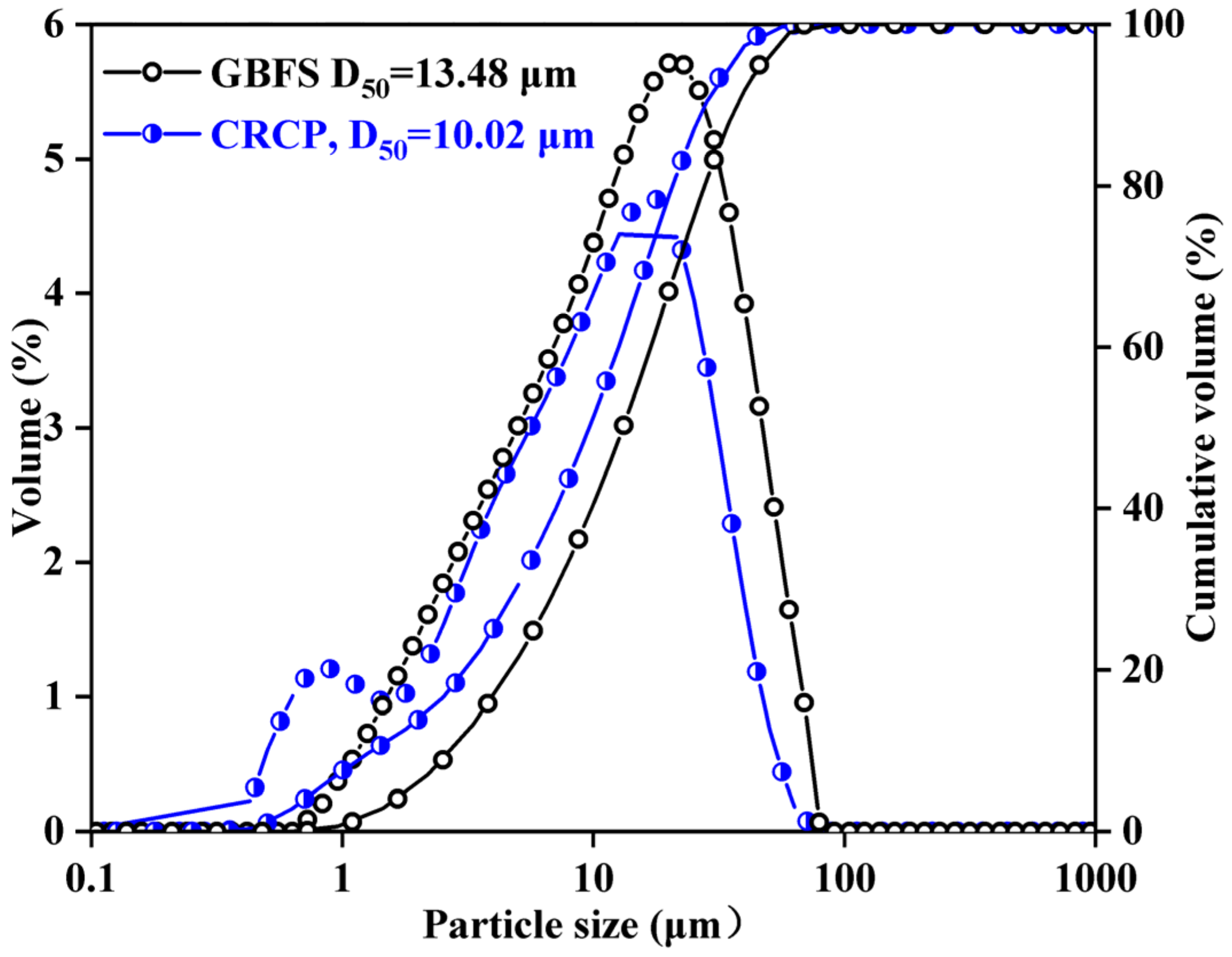
2.2. Preparation and Characterization of CRCF
2.3. Mortar Specimen Preparation
2.4. Test Methods
2.4.1. Hydration Heat
2.4.2. Hydration Products
2.4.3. Pore Structure
2.4.4. Compressive Strength
3. Results and Discussion
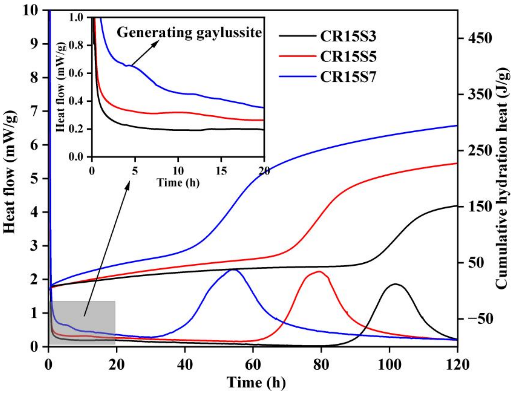
3.1. Hydration Heat
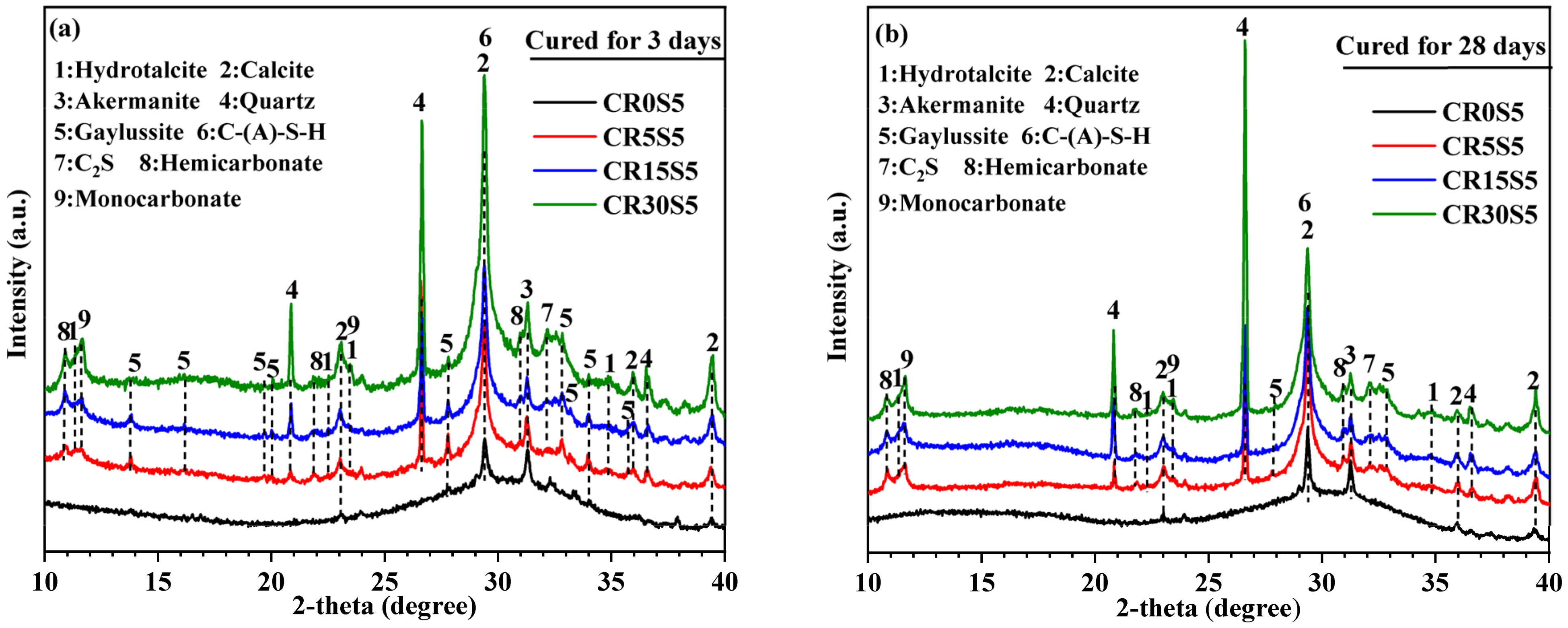
3.2. XRD Analysis
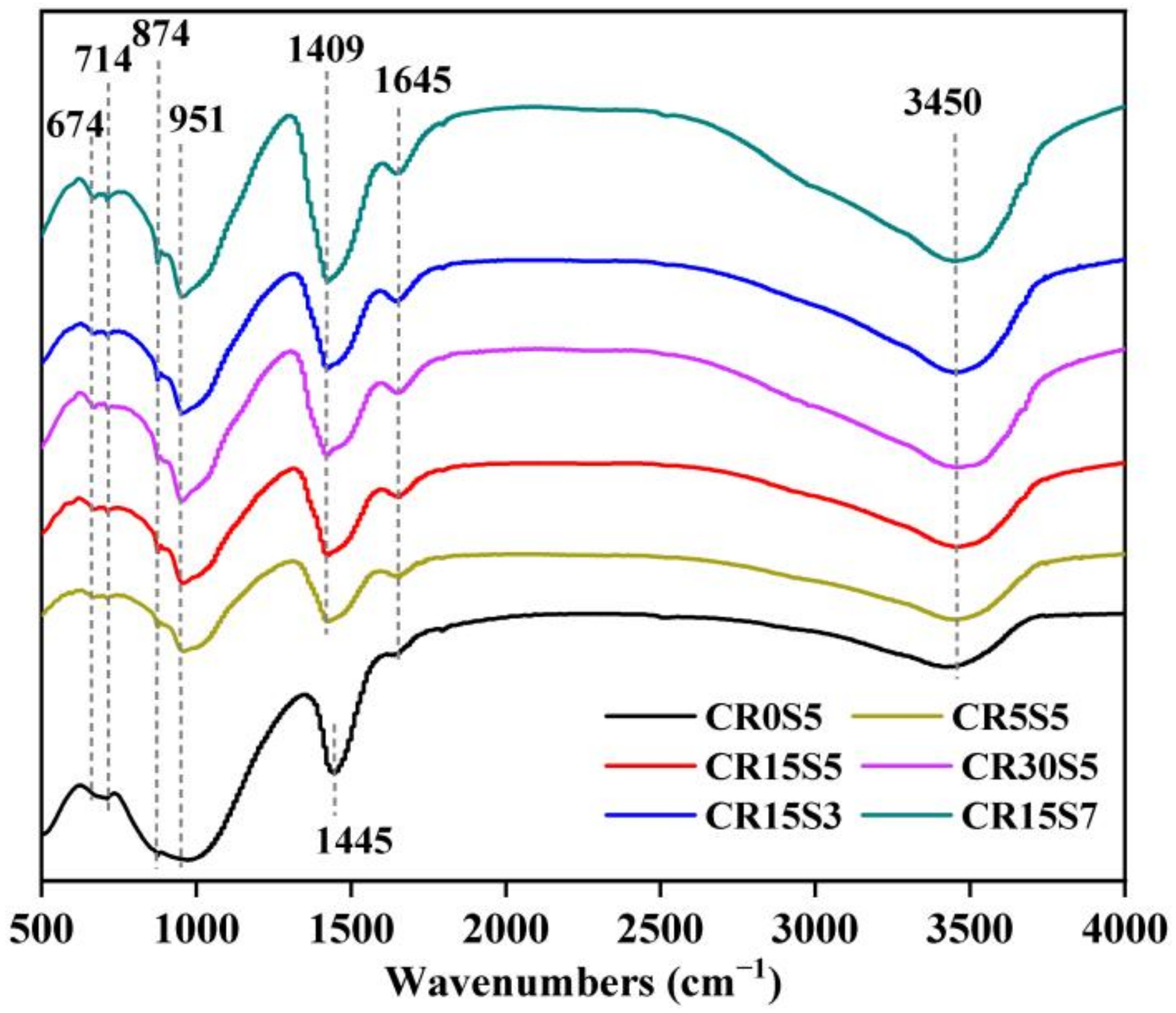
3.3. FTIR Analysis
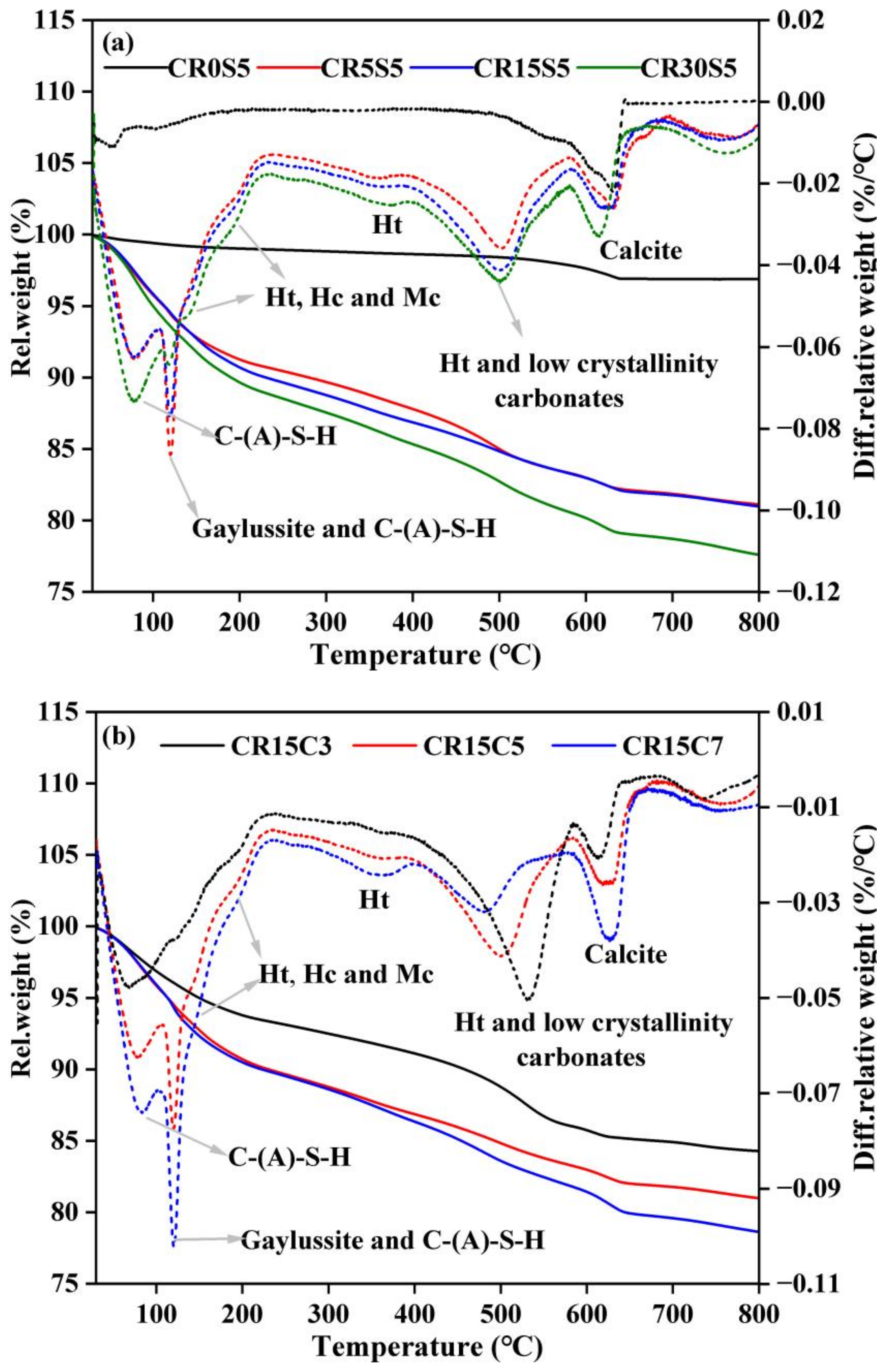
3.4. TG-DTG Analysis
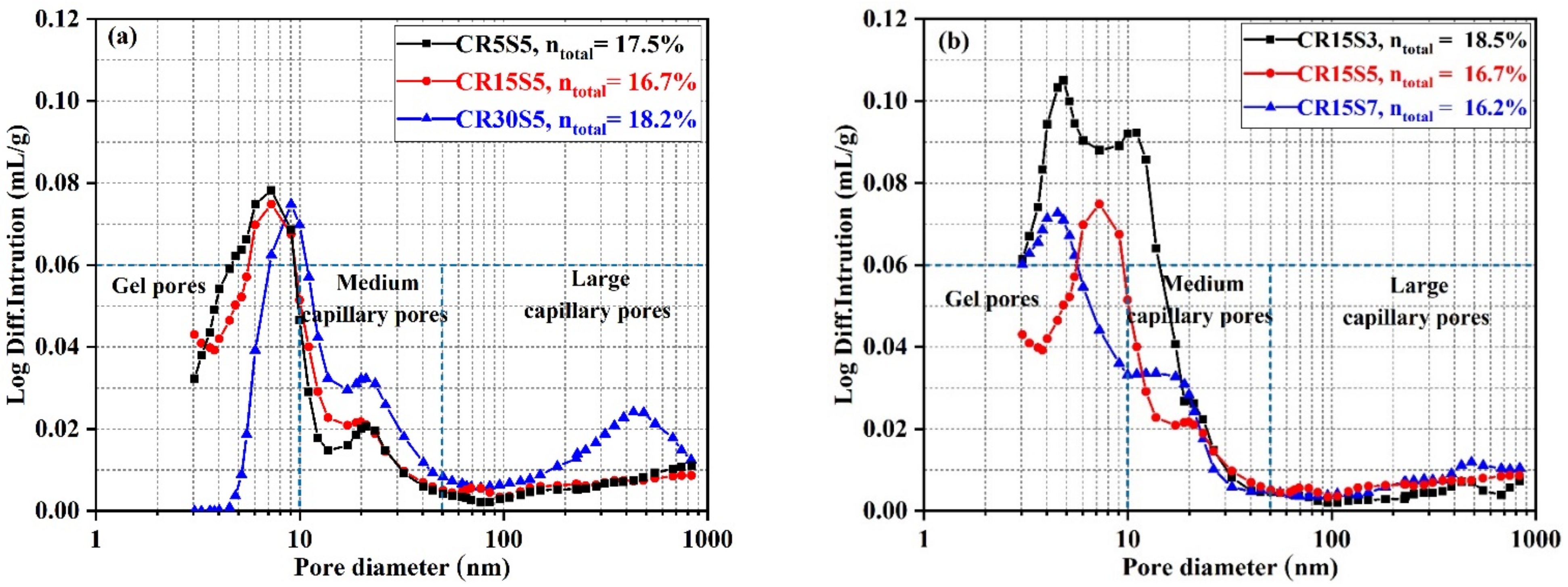
3.5. Pore Structure Evolution
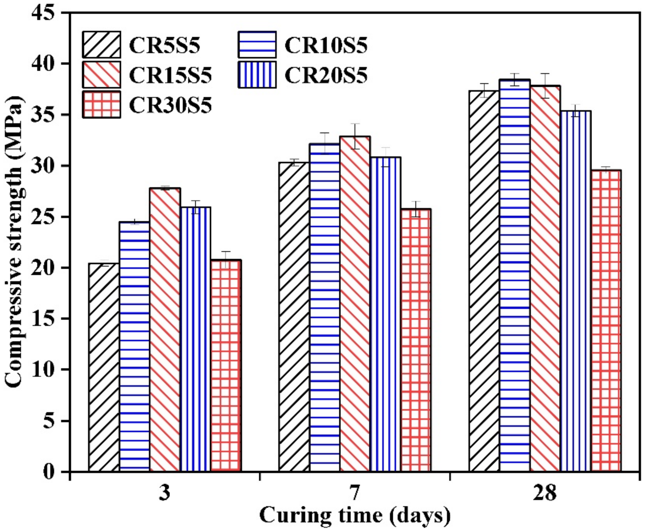
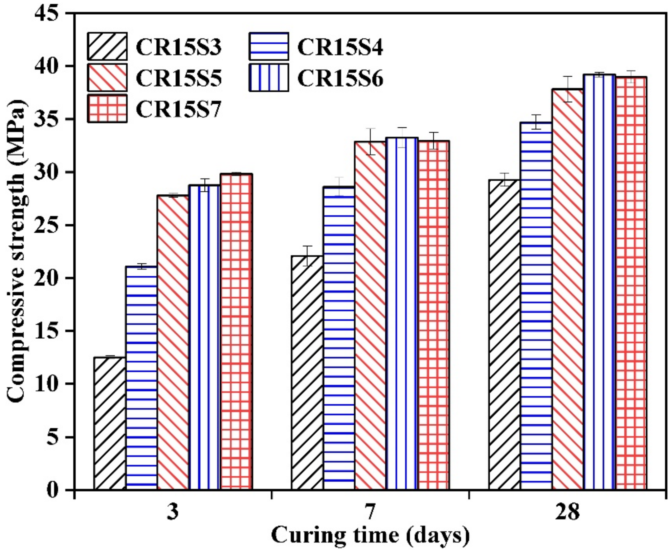
3.6. Compressive Strength
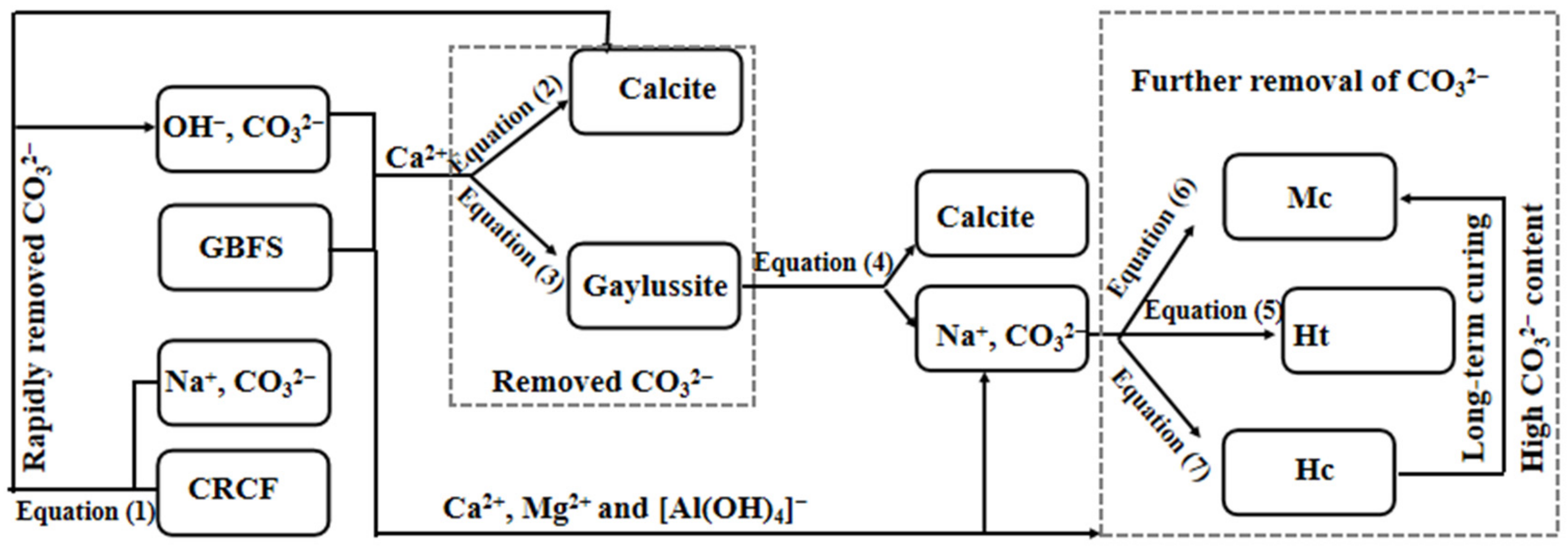
3.7. Acceleration Mechanism of CRCF on the Na2CO3-Activated GBFS Mortars
4. Conclusions
- (1)
- The GBFS was activated by one-part Na2CO3 and exhibited a slow reaction process with a long induction period (more than 120 h). CRCF incorporation significantly accelerated the dissolution of GBFS. In addition, the reaction kinetics can be further improved by increasing the Na2CO3 content.
- (2)
- The major phase assemblages of AAS mortars with different amounts of CRCF and Na2CO3 were the carbonates (calcite, gaylussite, Ht, Hc, and Mc) and the strength-giving phase (C-A-S-H). Both increasing the CRCF dosage and enhancing the Na2CO3 can promote the formation of carbonates, except for gaylussite (a transient phase).
- (3)
- Incorporating CRCF to a significant degree promoted the compressive strength development of AAS mortars, which can be further improved by increasing the amount of Na2CO3. The highest compressive strength (39.2 MPa) can be observed in AAS mortars with 6% Na2O-E and 15% CRCF.
Author Contributions
Funding
Conflicts of Interest
References
- Adesina, A. Performance and sustainability overview of sodium carbonate activated slag materials cured at ambient temperature. Resour. Environ. Sustain. 2021, 3, 100016. [Google Scholar] [CrossRef]
- Wang, H.; Wang, L.; Shen, W.; Cao, K.; Sun, L.; Wang, P.; Cui, L. Compressive strength, hydration and pore structure of alkali-activated slag mortars integrating with recycled concrete powder as binders. KSCE J. Civ. Eng. 2021, 26, 795–805. [Google Scholar] [CrossRef]
- Yin, K.; Jiang, Y.; He, H.; Ren, J.; Li, Z. Characterization of one-part alkali-activated slag with rice straw ash. Constr. Build. Mater. 2022, 345, 128403. [Google Scholar] [CrossRef]
- Wang, J.; Lyu, X.; Wang, L.; Cao, X.; Liu, Q.; Zang, H. Influence of the combination of calcium oxide and sodium carbonate on the hydration reactivity of alkali-activated slag binders. J. Clean. Prod. 2018, 171, 622–629. [Google Scholar] [CrossRef]
- Song, S.; Sohn, D.; Jennings, H.M.; Mason, T.O. Hydration of alkali-activated ground granulated blast furnace slag. J. Mater. Sci. 2000, 35, 249–257. [Google Scholar] [CrossRef]
- Akturk, B.; Kizilkanat, A.B.; Kabay, N. Effect of calcium hydroxide on fresh state behavior of sodium carbonate activated blast furnace slag pastes. Constr. Build. Mater. 2019, 212, 388–399. [Google Scholar] [CrossRef]
- Chen, Z.; Ye, H. The role of CaO and MgO incorporation in chloride resistance of sodium carbonate-activated slag. Cem. Concr. Compos. 2022, 132, 104625. [Google Scholar] [CrossRef]
- Akturk, B.; Abolfathi, M.; Ulukaya, S.; Kizilkanat, A.; Hooper, T.J.N.; Gu, L.; Yang, E.; Unluer, C. Hydration kinetics and performance of sodium carbonate-activated slag-based systems containing reactive MgO and metakaolin under carbonation. Cem. Concr. Compos. 2022, 132, 104617. [Google Scholar] [CrossRef]
- Bian, Z.; Jin, G.; Ji, T. Effect of combined activator of Ca(OH)2 and Na2CO3 on workability and compressive strength of alkali-activated ferronickel slag system. Cem. Concr. Compos. 2021, 123, 104179. [Google Scholar] [CrossRef]
- Shi, C.; Qu, B.; Provis, J.L. Recent progress in low-carbon binders. Cem. Concr. Res. 2019, 122, 227–250. [Google Scholar] [CrossRef]
- Abdalqader, A.F.; Jin, F.; Al-Tabbaa, A. Development of greener alkali-activated cement: Utilization of sodium carbonate for activating slag and fly ash mixtures. J. Clean. Prod. 2016, 113, 66–75. [Google Scholar] [CrossRef]
- Gao, X.; Yao, X.; Yang, T.; Zhou, S.; Wei, H.; Zhang, Z. Calcium carbide residue as auxiliary activator for one-part sodium carbonate-activated slag cements: Compressive strength, phase assemblage and environmental benefits. Constr. Build. Mater. 2021, 308, 125015. [Google Scholar] [CrossRef]
- Mohamed, O.A. A review of durability and strength characteristics of alkali-activated slag concrete. Materials 2019, 12, 1198. [Google Scholar] [CrossRef] [PubMed] [Green Version]
- Burciaga-Díaz, O. Parameters affecting the properties and microstructure of quicklime (CaO)—Activated slag cement pastes. Cem. Concr. Compos. 2019, 103, 104–111. [Google Scholar] [CrossRef]
- He, J.; Zheng, W.; Bai, W.; Hu, T.; Song, X. Effect of reactive MgO on hydration and properties of alkali-activated slag pastes with different activators. Constr. Build. Mater. 2020, 271, 121608. [Google Scholar] [CrossRef]
- Dung, N.T.; Hooper, T.; Unluer, C. Improving the carbonation resistance of Na2CO3-activated slag mixes via the use of reactive MgO and nucleation seeding. Cem. Concr. Compos. 2021, 115, 103832. [Google Scholar] [CrossRef]
- Fei, J.; Abir, A. Strength and drying shrinkage of slag paste activated by sodium carbonate and reactive MgO. Constr. Build. Mater. 2015, 81, 58–65. [Google Scholar]
- Jeon, D.; Jun, Y.; Jeong, Y.; Oh, J.E. Microstructural and strength improvements through the use of Na2CO3 in a cementless Ca(OH)2-activated class F fly ash system. Cem. Concr. Res. 2015, 67, 215–225. [Google Scholar] [CrossRef]
- Tang, Q.; Ma, Z.M.; Wu, H.X.; Wang, W. The utilization of eco-friendly recycled powder from concrete and brick waste in new concrete: A critical review. Cem. Concr. Compos. 2020, 114, 103807. [Google Scholar] [CrossRef]
- Xiao, J.Z.; Ma, Z.M.; Sui, T.B.; Akbarnezhad, A.; Duan, Z.H. Mechanical properties of concrete mixed with recycled powder produced from construction and demolition waste. J. Clean. Prod. 2018, 188, 720–731. [Google Scholar] [CrossRef]
- Gupta, T.; Siddique, S.; Sharma, R.K.; Chaudhary, S. Behaviour of waste rubber powder and hybrid rubber concrete in aggressive environment. Constr. Build. Mater. 2019, 217, 283–291. [Google Scholar] [CrossRef]
- Li, S.; Li, Q.; Zhao, X.; Luo, J.; Gao, S.; Yue, G.; Su, D. Experimental study on the preparation of recycled admixtures by using construction and demolition waste. Materials 2019, 12, 1678. [Google Scholar] [CrossRef] [PubMed] [Green Version]
- Mao, X.; Qu, W.; Zhu, P.; Xiao, J. Influence of recycled powder on chloride penetration resistance of green reactive powder concrete. Constr. Build. Mater. 2020, 251, 119049. [Google Scholar] [CrossRef]
- Kim, J.; Jang, H. Closed-loop recycling of C&D waste: Mechanical properties of concrete with the repeatedly recycled C&D powder as partial cement replacement. J. Clean. Prod. 2022, 343, 130977. [Google Scholar]
- Shen, P.; Sun, Y.; Liu, S.; Zheng, H.; Chi, S.P. Synthesis of amorphous nano-silica from recycled concrete fines by two-step wet carbonation. Cem. Concr. Res. 2021, 147, 106526. [Google Scholar] [CrossRef]
- Sui, Y.; Ou, C.; Liu, S.; Zhang, J.; Tian, Q. Study on properties of waste concrete powder by thermal treatment and application in mortar. Appl. Sci. 2020, 10, 998. [Google Scholar] [CrossRef] [Green Version]
- Qian, D.; Yu, R.; Shui, Z.; Sun, Y.; He, Y. A novel development of green ultra-high performance concrete (UHPC) based on appropriate application of recycled cementitious material. J. Clean. Prod. 2020, 261, 121231. [Google Scholar] [CrossRef]
- Menchaca-Ballinas, L.E.; Gorokhovsky, A.V.; Escalante-Garcia, J.I. Waste glass as a precursor in sustainable hydraulic cements activated with CaO-NaOH-Na2CO3. Constr. Build. Mater. 2021, 302, 124099. [Google Scholar] [CrossRef]
- Saillioa, M.; Sabeurbc, H.; Vincenta, J.; Zitouna, B. Phase assemblage of a 5 year-old cement paste after submission to various high temperature and cooling regime. Constr. Build. Mater. 2021, 279, 122440. [Google Scholar] [CrossRef]
- Hu, S.; He, Y. Preparation of regeneration binding material using waste concrete. J. Chin. Ceram. Soc. 2007, 35, 593–599. [Google Scholar]
- ASTM C1702-17; Standard Test Method for Measurement of Heat of Hydration of Hydraulic Cementitious Materials Using Isothermal Conduction Calorimetry. ASTM International: West Conshohocken, PA, USA, 2017.
- ASTM C109; Standard Test Method for Compressive Strength of Hydraulic Cement Mortars. ASTM International: West Conshohocken, PA, USA, 2016.
- Dung, N.T.; Hooper, T.J.N.; Unluer, C. Accelerating the reaction kinetics and improving the performance of Na2CO3-activated GGBS mixes. Cem. Concr. Res. 2019, 126, 105927. [Google Scholar] [CrossRef]
- Wang, Y.S.; Tae, S.H.; Lin, R.S.; Wang, X.Y. Effects of Na2CO3 on engineering properties of cement–limestone powder–slag ternary blends. J. Build. Eng. 2022, 57, 104937. [Google Scholar] [CrossRef]
- Kim, M.S.; Jun, Y.; Lee, C.; Oh, J.E. Use of CaO as an activator for producing a price-competitive non-cement structural binder using ground granulated blast furnace slag. Cem. Concr. Res. 2013, 54, 208–214. [Google Scholar] [CrossRef]
- Avet, F.; Scrivener, K. Investigation of the calcined kaolinite content on the hydration of Limestone Calcined Clay Cement (LC3). Cem. Concr. Res. 2018, 107, 124–135. [Google Scholar] [CrossRef]
- Yuan, B.; Yu, Q.; Brouwers, H. Evaluation of slag characteristics on the reaction kinetics and mechanical properties of Na2CO3 activated slag. Constr. Build. Mater. 2017, 131, 334–346. [Google Scholar] [CrossRef]
- Yuan, B.; Yu, Q.; Brouwers, H. Time-dependent characterization of Na2CO3 activated slag. Cem. Concr. Compos. 2017, 84, 188–197. [Google Scholar] [CrossRef]
- Sun, X.; Liu, J.; Qiu, J.; Wu, P.; Zhao, Y. Alkali activation of blast furnace slag using a carbonate-calcium carbide residue alkaline mixture to prepare cemented paste backfill. Constr. Build. Mater. 2022, 320, 126234. [Google Scholar] [CrossRef]
- Ling, X.; Schollbachb, K.; Liu, G.; Brouwers, H. The utilization of waste incineration filter dust (WIFD) in sodium carbonate activated slag mortars. Constr. Build. Mater. 2021, 313, 125494. [Google Scholar] [CrossRef]
- Yang, T.; Zhang, Z.; Zhu, H.; Zhang, W.; Gao, Y.; Zhang, X.; Wu, Q. Effects of calcined dolomite addition on reaction kinetics of one-part sodium carbonate-activated slag cements. Constr. Build. Mater. 2019, 211, 329–336. [Google Scholar] [CrossRef]
- Zhang, J.; Tan, H.; Cai, L.; He, X.; Liu, X. Ultra-fine slag activated by sodium carbonate at ambient temperature. Constr. Build. Mater. 2020, 264, 120695. [Google Scholar] [CrossRef]
- Gao, X.; Yao, X.; Wang, C.; Geng, C.; Yang, T. Properties and microstructure of eco-friendly alkali-activated slag cements under hydrothermal conditions relevant to well cementing applications. Constr. Build. Mater. 2022, 318, 125973. [Google Scholar] [CrossRef]
- Bernal, S.A.; Provis, J.L.; Myers, R.J.; Nicolas, R.S.; Deventer, J. Role of carbonates in the chemical evolution of sodium carbonate-activated slag binders. Mater. Struct. 2015, 48, 517–529. [Google Scholar] [CrossRef]


| Raw Materials | Chemical Composition (wt.%) | ||||||
|---|---|---|---|---|---|---|---|
| SiO2 | Al2O3 | CaO | MgO | Fe2O3 | Na2O | SO3 | |
| GBFS | 27.2 | 15.5 | 44.8 | 8.0 | 0.3 | 0.3 | 2.3 |
| CRCF | 28. 4 | 7.0 | 56.1 | 1.4 | 3.0 | 0.3 | 2.1 |
| Code | GBFS/g | CRCF/g | Sand/g | Na2CO3/g | Na2O-E/% | Water/g |
|---|---|---|---|---|---|---|
| CR0S5 | 344.8 | 0 | 500 | 29.5 | 5 | 155.2 |
| CR5S5 | 327.6 | 17.2 | 500 | 29.5 | 5 | 155.2 |
| CR10S5 | 310.3 | 34.5 | 500 | 29.5 | 5 | 155.2 |
| CR15S5 | 293.1 | 51.7 | 500 | 29.5 | 5 | 155.2 |
| CR20S5 | 274.8 | 70.0 | 500 | 29.5 | 5 | 155.2 |
| CR30S5 | 241.4 | 103.4 | 500 | 29.5 | 5 | 155.2 |
| CR15S3 | 293.1 | 51.7 | 500 | 17.7 | 3 | 155.2 |
| CR15S4 | 293.1 | 51.7 | 500 | 23.6 | 4 | 155.2 |
| CR15S6 | 293.1 | 51.7 | 500 | 35.4 | 6 | 155.2 |
| CR15S7 | 293.1 | 51.7 | 500 | 41.3 | 7 | 155.2 |
| Mix | Dehydration of Bound Water | Dehydroxylaztion of Ht | Decarbonation of Ht and Low-Crystallinity Carbonates | Decarbonation of Calcite | ||||
|---|---|---|---|---|---|---|---|---|
| 40–250 °C | 300–400 °C | 450–600 °C | 600–700 °C | |||||
| 3 d | 28 d | 3 d | 28 d | 3 d | 28 d | 3 d | 28 d | |
| CR0S5 | 0.94 | 1.66 | 0.20 | 0.84 | 0.92 | 0.89 | 0.73 | 1.60 |
| CR5S5 | 8.26 | 9.65 | 1.75 | 2.10 | 3.58 | 3.36 | 1.40 | 1.74 |
| CR15S5 | 8.46 | 10.09 | 1.98 | 2.42 | 4.35 | 3.39 | 1.34 | 2.45 |
| CR30S5 | 9.40 | 9.60 | 2.36 | 2.47 | 4.85 | 4.02 | 1.41 | 2.66 |
| CR15S3 | 6.21 | 7.06 | 1.45 | 1.66 | 4.74 | 3.42 | 0.83 | 1.65 |
| CR15S7 | 10.10 | 10.16 | 2.27 | 2.47 | 3.70 | 3.15 | 1.83 | 2.55 |
Publisher’s Note: MDPI stays neutral with regard to jurisdictional claims in published maps and institutional affiliations. |
© 2022 by the authors. Licensee MDPI, Basel, Switzerland. This article is an open access article distributed under the terms and conditions of the Creative Commons Attribution (CC BY) license (https://creativecommons.org/licenses/by/4.0/).
Share and Cite
Wang, H.; Wang, L.; Xu, Y.; Cao, K.; Ge, Y.; Wang, X.; Li, Q. Accelerating the Reaction Kinetics of Na2CO3-Activated Slag Mortars by Calcined Recycled Concrete Fines. Materials 2022, 15, 5375. https://doi.org/10.3390/ma15155375
Wang H, Wang L, Xu Y, Cao K, Ge Y, Wang X, Li Q. Accelerating the Reaction Kinetics of Na2CO3-Activated Slag Mortars by Calcined Recycled Concrete Fines. Materials. 2022; 15(15):5375. https://doi.org/10.3390/ma15155375
Chicago/Turabian StyleWang, Hao, Liang Wang, Ying Xu, Ke Cao, Yan Ge, Xuepeng Wang, and Qi Li. 2022. "Accelerating the Reaction Kinetics of Na2CO3-Activated Slag Mortars by Calcined Recycled Concrete Fines" Materials 15, no. 15: 5375. https://doi.org/10.3390/ma15155375
APA StyleWang, H., Wang, L., Xu, Y., Cao, K., Ge, Y., Wang, X., & Li, Q. (2022). Accelerating the Reaction Kinetics of Na2CO3-Activated Slag Mortars by Calcined Recycled Concrete Fines. Materials, 15(15), 5375. https://doi.org/10.3390/ma15155375