
A Study on the Residual Stress of the Co-Based Alloy Plasma Cladding Layer


Abstract
:1. Introduction
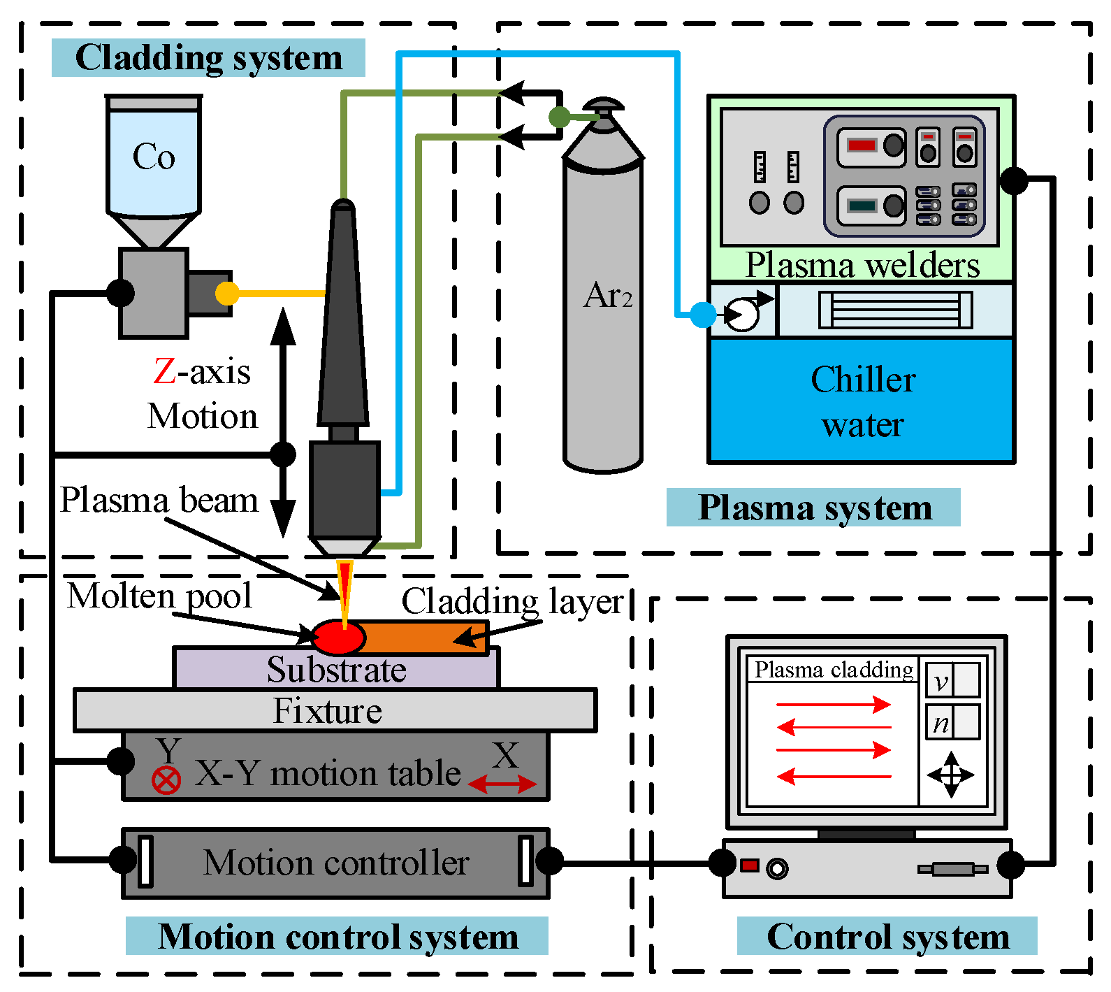
2. Establishment of Finite Element Model
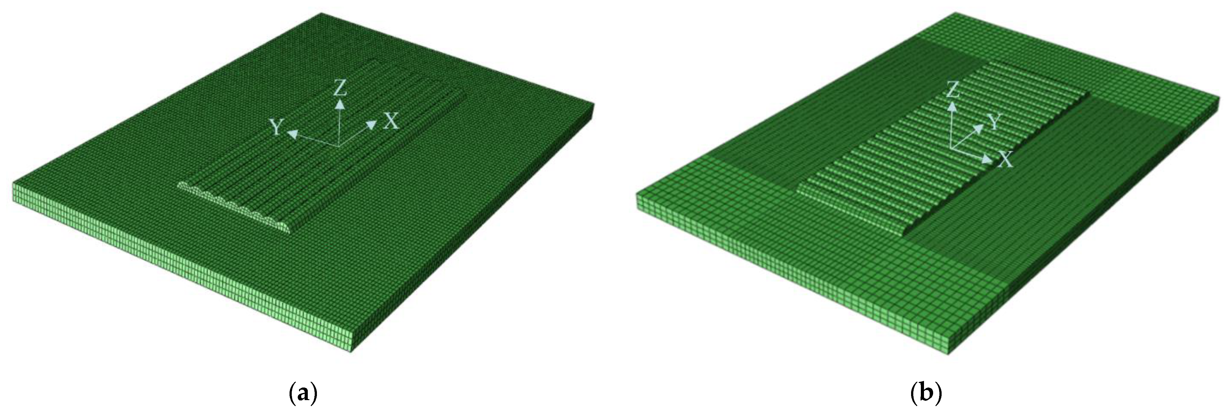
2.1. Simplification of Finite Element Model
- The cladding powder was isotropic with the substrate material;
- The convective heat transfer coefficient was constant in the cladding simulation process;
- The vaporization effect of the cladding powder was not considered;
- The whole cladding process followed the Van Mises stress criterion;
- The moving heat source was always stable;
- The interaction between process parameters was ignored.
2.2. Simplification of Finite Element Model
2.3. Imposition of Boundary Conditions
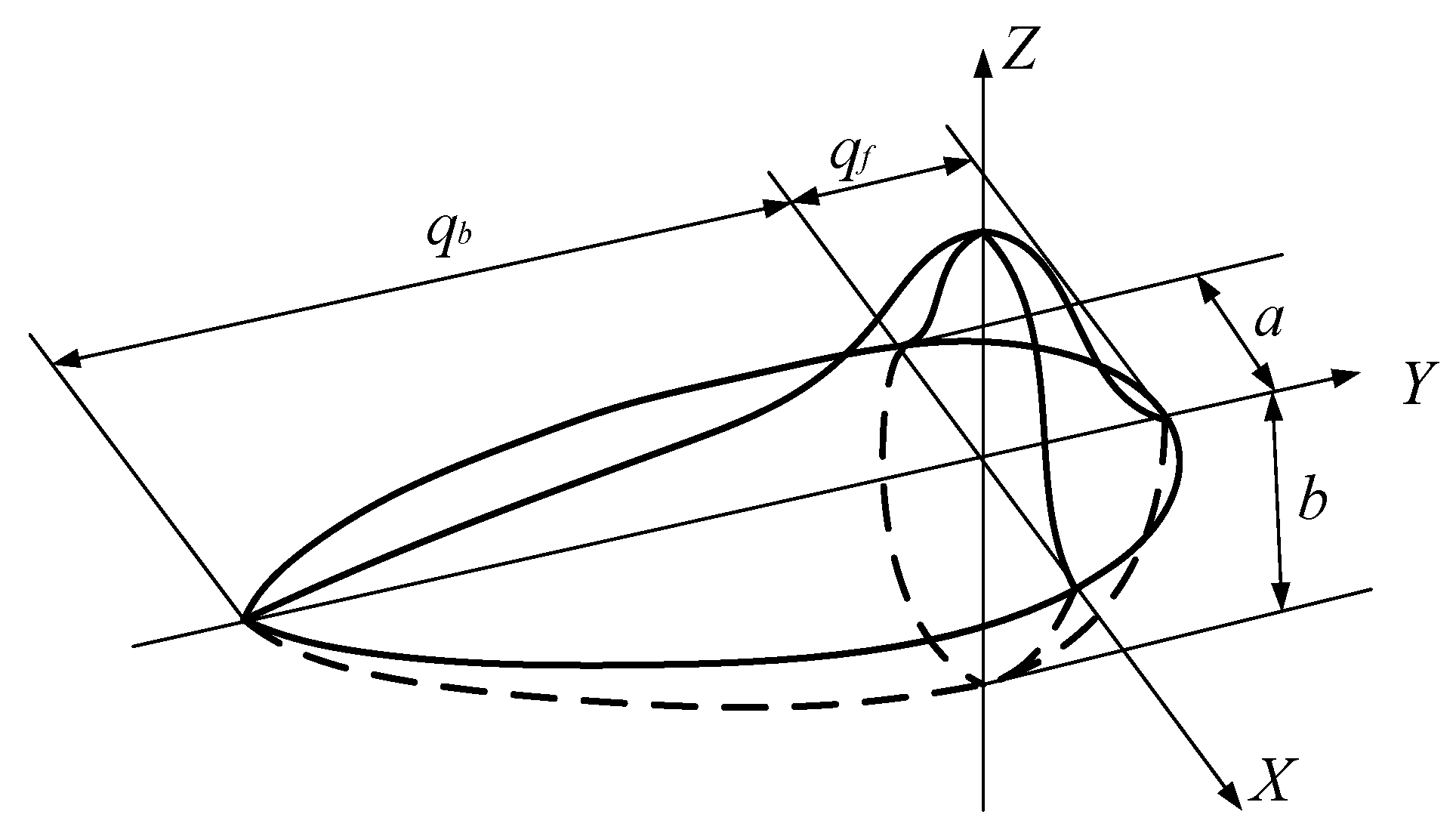
2.4. Mobile Heat Source
3. Stress Field Analysis of Plasma Cladding
3.1. Influence of Working Current on Residual Stress
3.2. Influence of Scanning Speed on Residual Stress
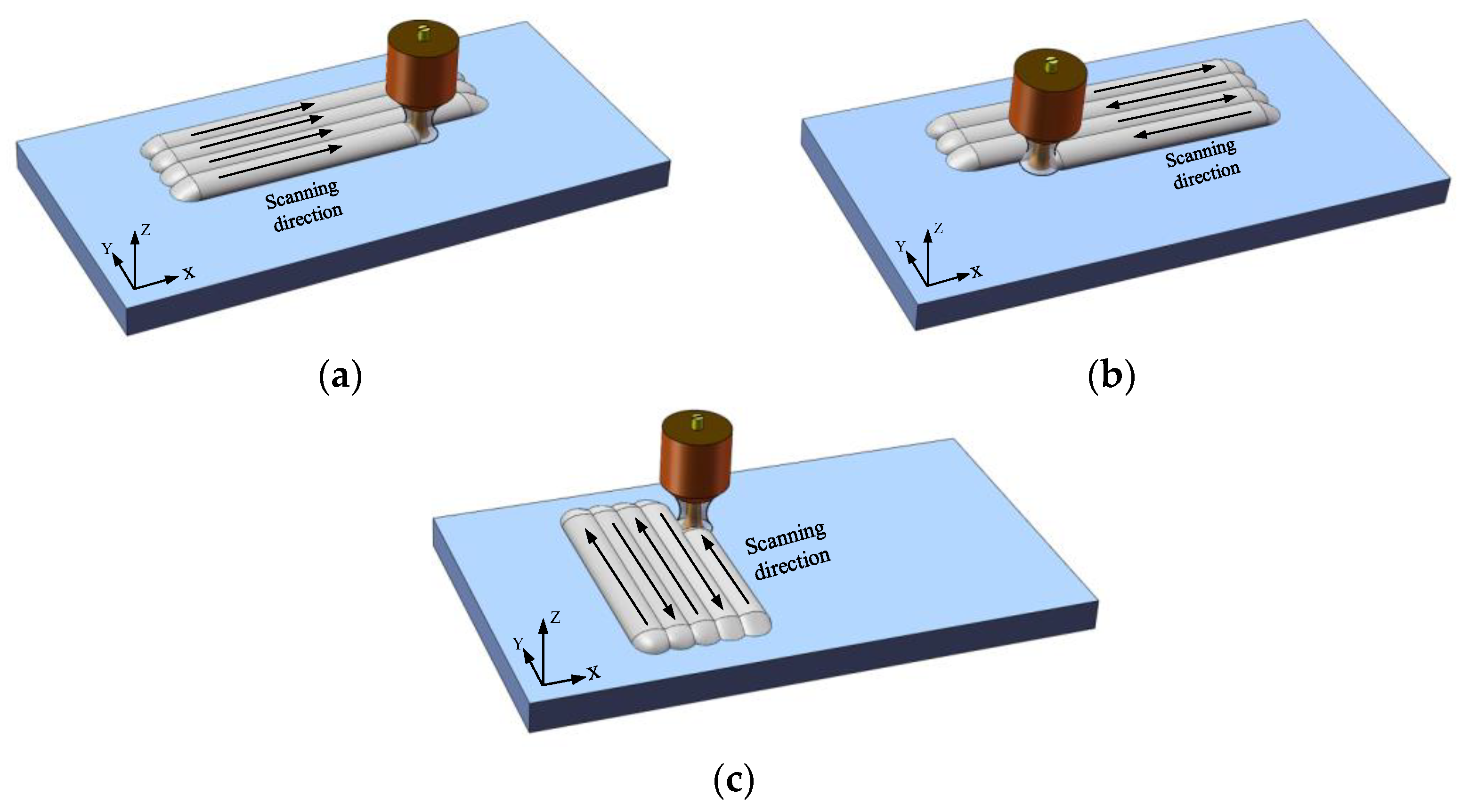
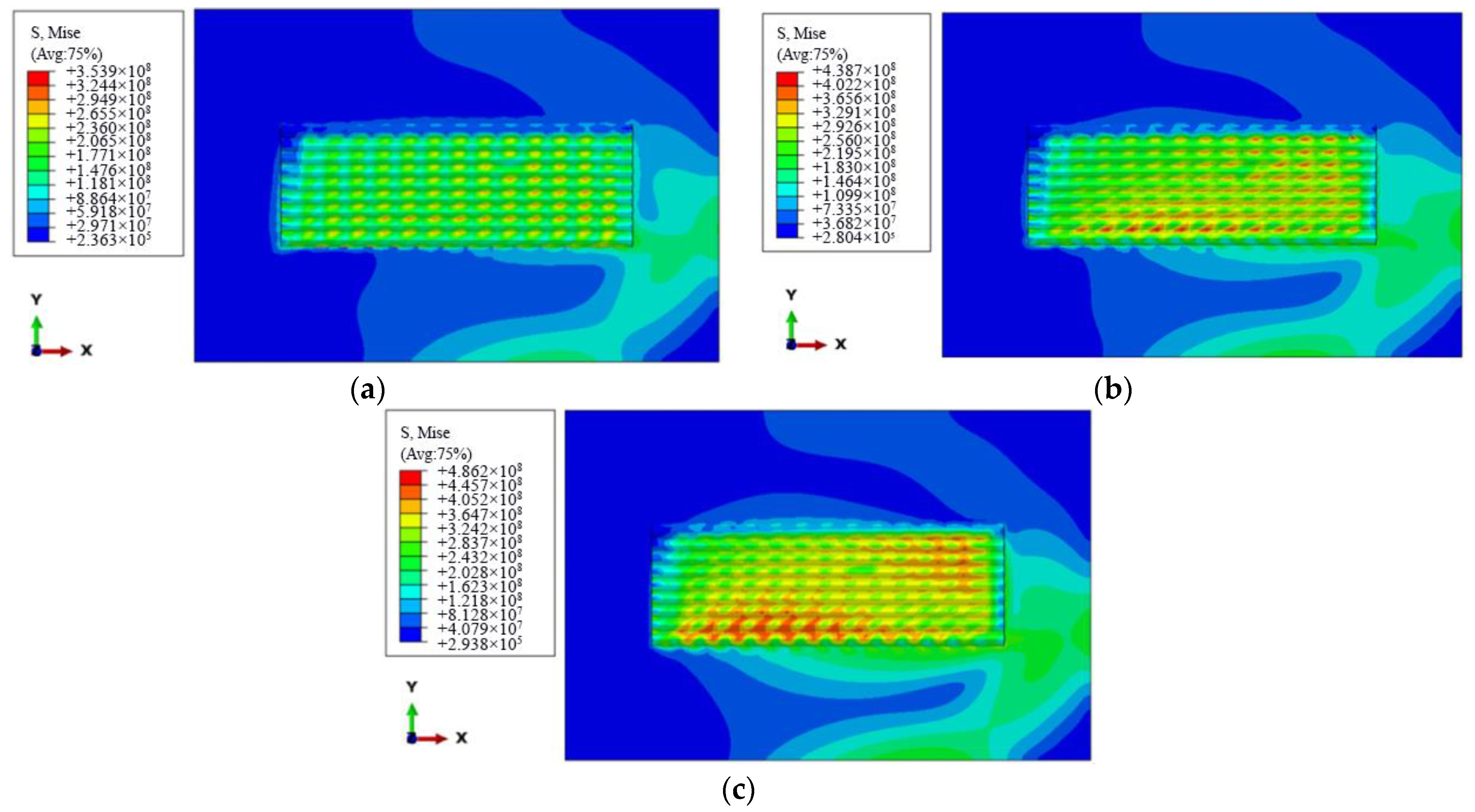
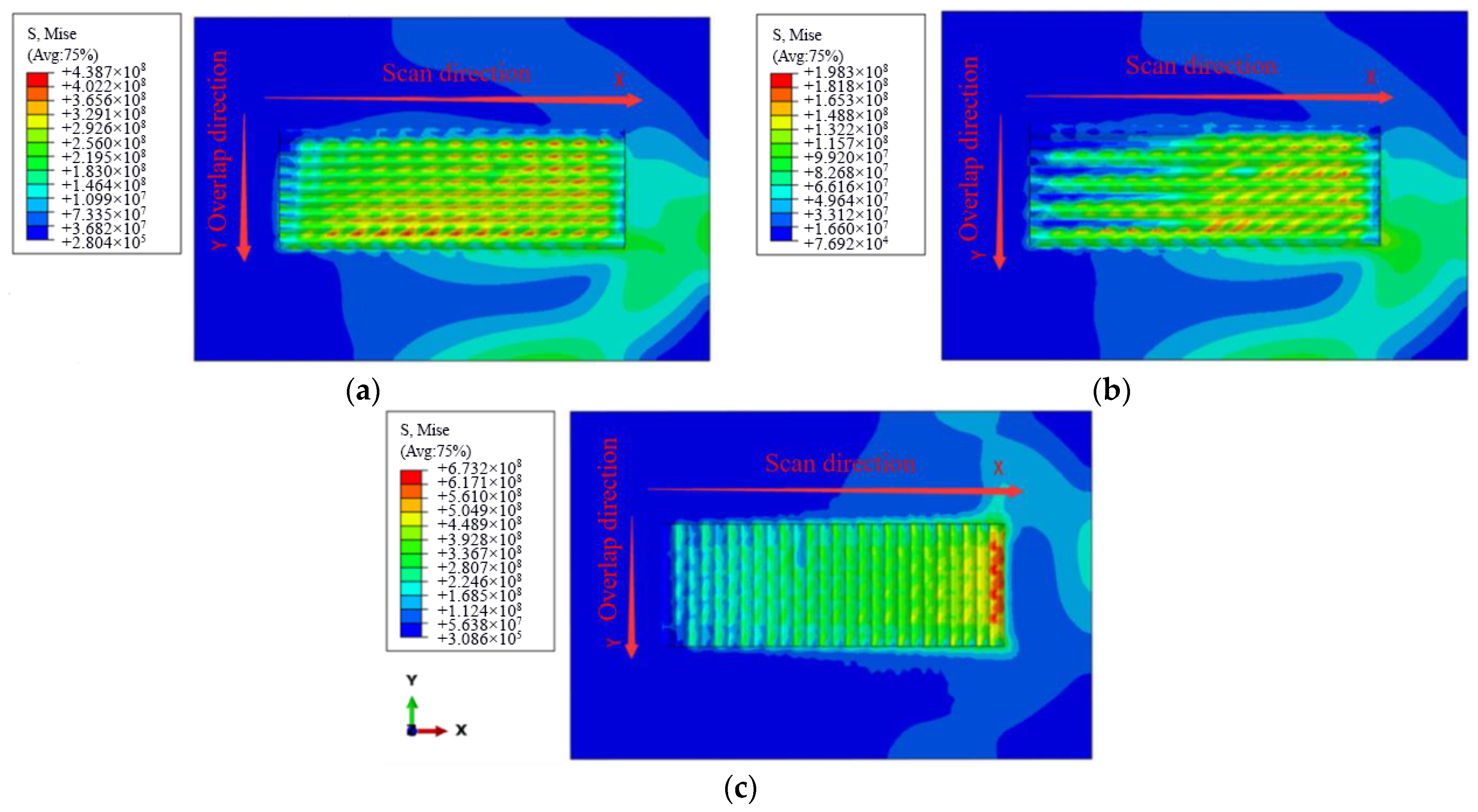
3.3. Influence of Scanning mode on Residual Stress
4. Verification Test
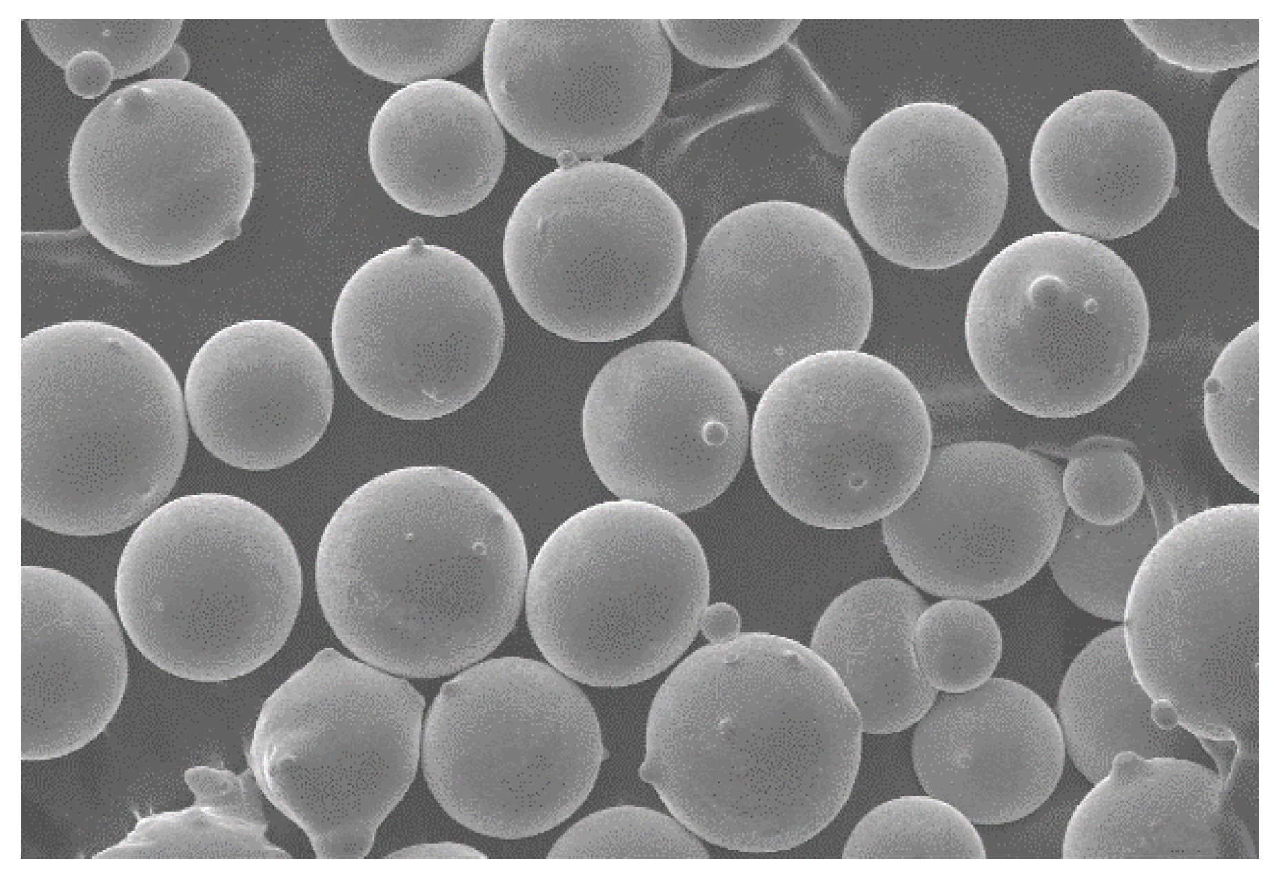
4.1. Test Materials
4.2. Sample Preparation
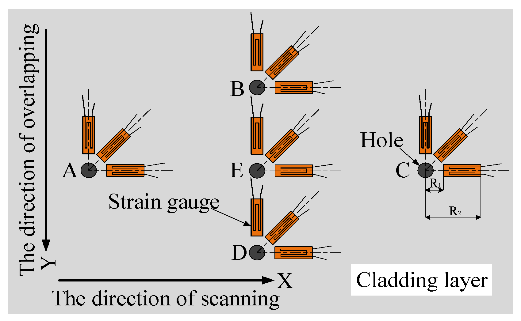
4.3. Residual Stress Measurement by Blind Hole Method
- (1)
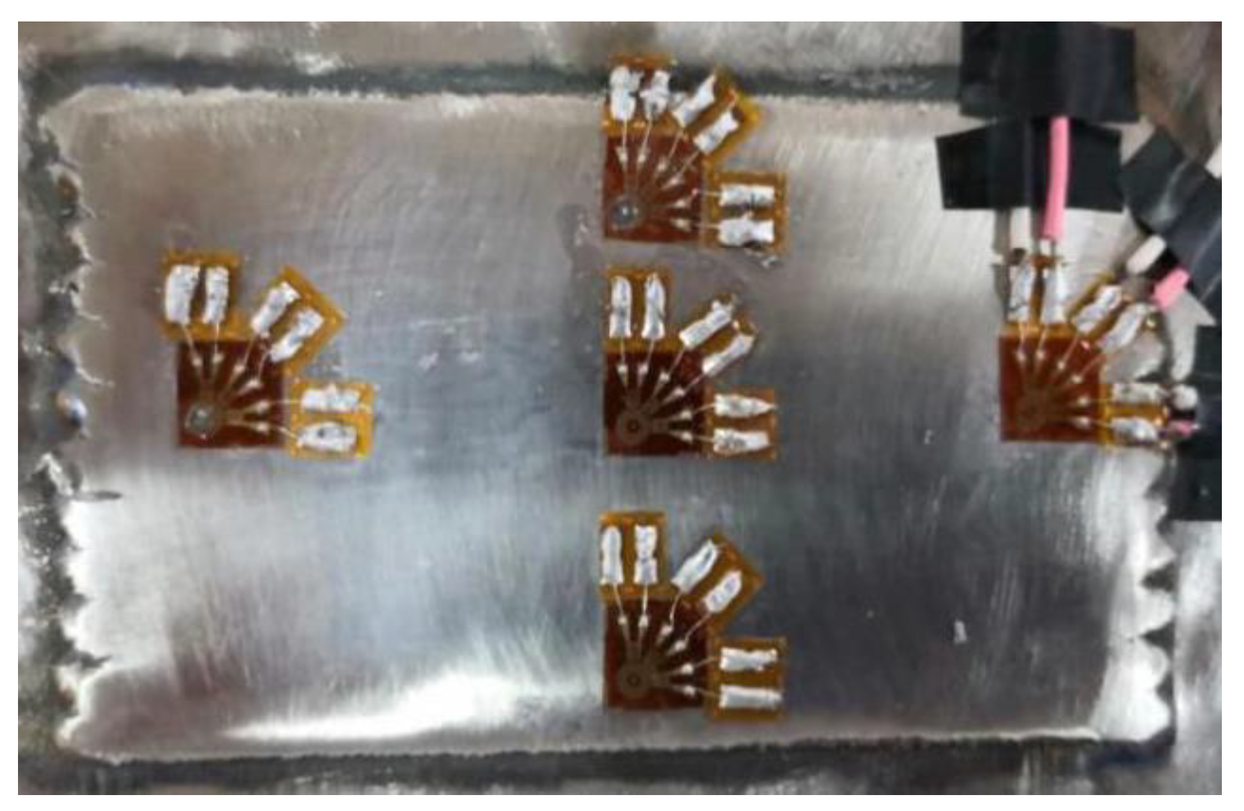
- The strain gauge was pasted at the position where the residual stress of the cladding layer was to be measured. Before the strain gauge was pasted, the surface of the cladding layer was polished, and acetone was used for cleaning the cladding layer to ensure that the strain gauge could be closely adhered to it. After the strain gauge was pasted with 502 glue, it would be placed for 24 h before subsequent operation. (The strain gauge placement position is shown in Figure 10).
- (2)
- The indicator of the strain gauge was adjusted to zero, and the borehole was started. In order to reduce the influence of the plastic deformation at the borehole edge on the measurement accuracy [18], the distance between the borehole center and the sensitive grating of the strain gauge was 2 mm. Firstly, a drill bit with a diameter of 1 mm was selected to determine the position of the hole center, and then the drill bit with a diameter of 2 mm was used for drilling. The drilling depth was 2 mm. (The residual stress test sample is shown in Figure 11).
- (3)
- The additional strain generated by drilling heat during drilling would have a certain impact on the reading, so it should be kept for 20 min after drilling. After the hole edge returned to the initial temperature, a group of readings was read every 5 min until the adjacent two readings were the same. The average value of the three groups of values was taken as the strain value [19].
4.4. Calculation of Residual Stress
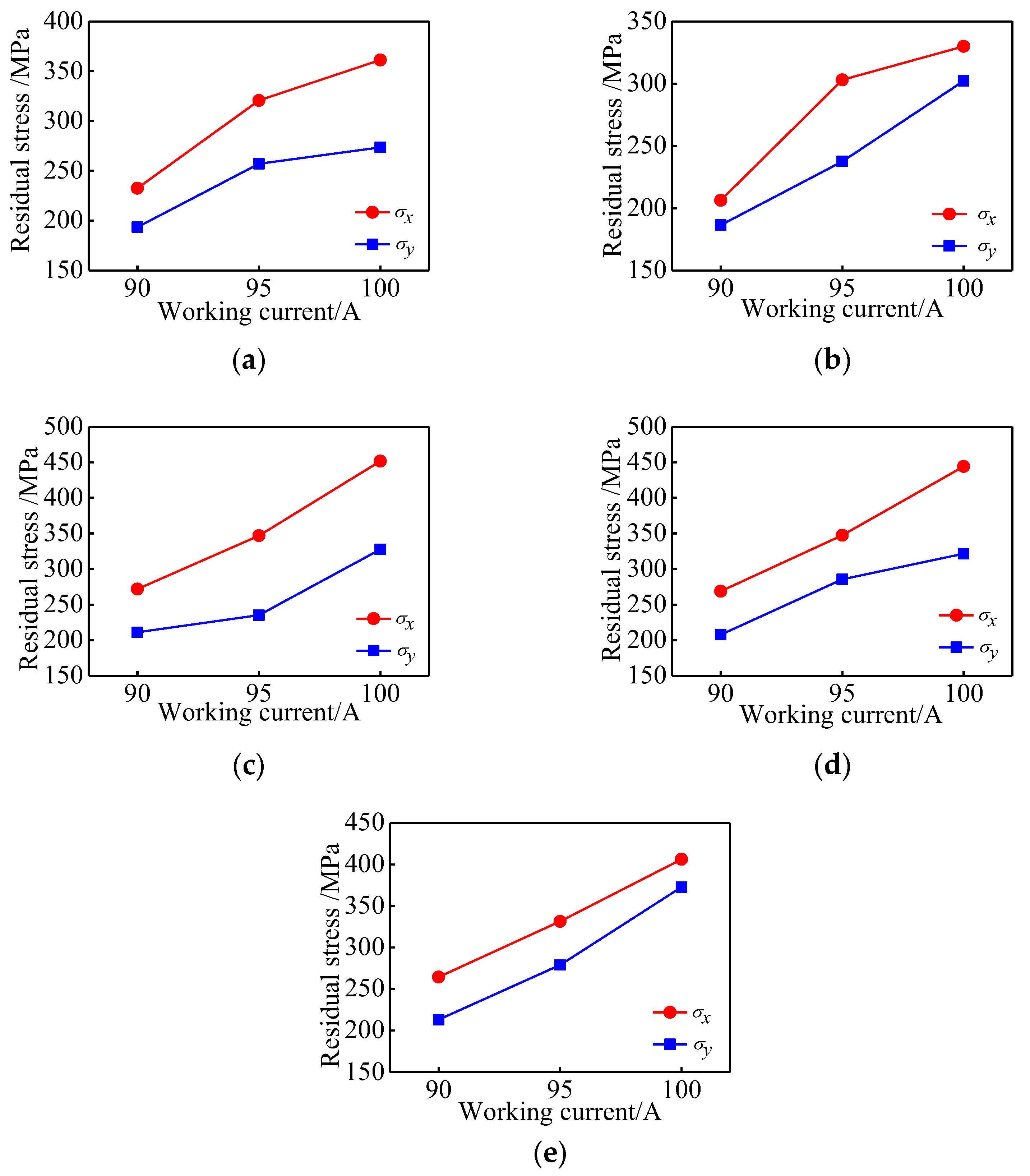
4.5. Influence of Working Current on Residual Stress
4.6. Influence of Scanning Speed on Residual Stress
4.7. Influence of Scanning mode on Residual Stress
5. Conclusions
- (1)
- The residual stress on the surface of the cladding layer is tensile stress, and the residual stress along the scanning path is greater than that along the scanning direction ( > ). Both directions are the direction of increasing residual stress.
- (2)
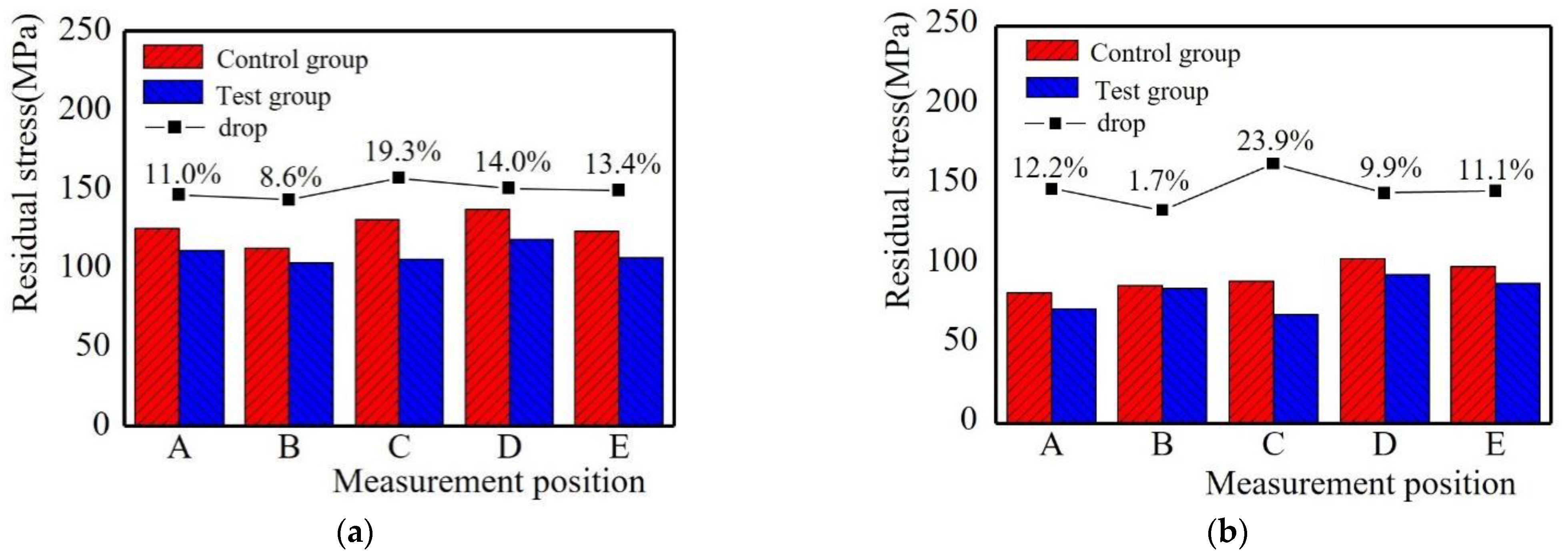
- The residual stress increases with the increase of the working current. The scanning speed is larger, and the residual stress is smaller. The residual stress of the short-edge scanning mode is greater than that of the long-edge scanning mode. The residual stress in a successive scanning mode is greater than that in a reciprocating scanning mode. The residual stress of the specimen obtained by long-edge reciprocating scanning is the smallest, which is the best scanning mode.
- (3)
- The working current 90 A and the scanning speed 100 mm/min is the best combination of process parameters. Long-edge reciprocating is the best scanning mode.
Author Contributions
Funding
Data Availability Statement
Acknowledgments
Conflicts of Interest
References
- Xie, Z.; Zhang, C.; Wang, R.; Li, D.; Zhang, Y.; Li, G.; Lu, X. Microstructure and wear resistance of wc/cobased coating on copper by plasma cladding. J. Mater. Res. Technol. 2021, 15, 821–833. [Google Scholar] [CrossRef]
- Xu, H.; Huang, H. Plasma remelting and injection method for fabricating metal matrix composite coatings reinforced with tungsten carbide. Ceram. Int. 2022, 48, 2645–2659. [Google Scholar] [CrossRef]
- Yang, X.; Li, C.; Zhang, M.; Ye, Z.; Zhang, X.; Zheng, M.; Gu, J.; Zhu, H.; Wang, F. Study on tensile and thermal fatigue behaviors of additively manufactured cobalt-based alloys alloying with Al And Ni. Mater. Sci. Eng. A 2022, 840, 142914. [Google Scholar] [CrossRef]
- Fang, Y.; Cui, X.; Cai, Z.; Wang, C.; Jin, G. Influence of La2O3 Addition on Nano Indentation Hardness and Residual Stress of Stellite 6 Coating Prepared by Plasma Cladding. J. Rare Earths 2018, 36, 873–878. [Google Scholar] [CrossRef]
- Zhou, Y.X.; Zhang, J.; Xing, Z.G.; Wang, H.D.; Lv, Z.L. Microstructure and properties of nicrbsi coating by plasma cladding on gray cast iron. Surf. Coat. Technol. 2019, 361, 270–279. [Google Scholar] [CrossRef]
- Tang, M.Q.; Wang, J.F.; Feng, Z.Q.; Li, G.; Yan, Z.W.; Zhang, R.Z. Corrosion resistance of aln and fe3al reinforced fe-based plasma cladding layer in 3.5wt% nacl solution. Ceram. Int. 2019, 45, 16918–16926. [Google Scholar] [CrossRef]
- Shi, X.L.; Wang, C.M.; Huang, M.T.; Cui, H.Z. Microstructure and wear resistance property of al-fe-cr-ni-mo coatings by plasma cladding. Mater. Res. Express 2019, 6, 10. [Google Scholar] [CrossRef]
- Brunner-Schwer, C.; Petrat, T.; Graf, B.; Rethmeier, M. Highspeed-Plasma-Laser-Cladding of thin wear resistance coatings a process approach as a hybrid metal deposition-technology. Vacuum 2019, 166, 123–126. [Google Scholar] [CrossRef]
- Chu, Y.; Hao, B.; Li, Z.; Zhu, J.; He, X. An analytical model for predicting residual stresses in multiple layers by plasma cladding process. Aip Adv. 2019, 9, 085103. [Google Scholar] [CrossRef] [Green Version]
- Wang, C.M.; Yu, J.X.; Zhang, Y.; Yu, Y. Phase evolution and solidification cracking sensibility in laser re-melting treatment of the plasma-sprayed Cr-Mn-Fe-Co-Ni high entropy alloy coating. Mater. Des. 2019, 182, 108040. [Google Scholar] [CrossRef]
- Hu, Y.J.; Wan, J.; Yuan, L.; Zhang, T.; Cao, J.; Li, F.; Cheng, X.; Jie, X.; Zhang, H. Influence of the phase composition and microstructure of plasma cladding Fe-Cr-Ni-C alloy coating on residual stress and crack formation. Int. J. Adv. Manuf. Technol. 2018, 96, 1607–1613. [Google Scholar] [CrossRef]
- Li, Y.; Tan, N.; Jin, G.; Cui, X.; Li, Q. Thermal fatigue failure behavior of surface/interface of plasma cladding layer. Coatings 2019, 9, 646. [Google Scholar] [CrossRef] [Green Version]
- Zhang, Z.; Kovacevic, R. A thermo-mechanical model for simulating the temperature and stress distribution during laser cladding process. Int. J. Adv. Manuf. Technol. 2019, 102, 457–472. [Google Scholar] [CrossRef]
- Wang, L.-F.; Sun, Y.-X.; Zhu, G.-X.; Gong, C.; Song, T.-L. Optimization simulation of process parameters on the residual stress in 316L stainless steel by laser cladding. Appl. Laser 2019, 39, 376–380. [Google Scholar]
- Liu, X.-D.; Jiang, H.-L.; Xie, M. Analysis of residual stress in laser cladding of Q345 steel. Heat Treat. Met. 2020, 45, 226–230. [Google Scholar]
- Lai, Y.-B.; Wang, D.-Y.; Yang, B.; Wu, H.; Sun, H.; Li, X. Influence of process parameter on the residual stress of the Co-based alloy plasma cladding. Surf. Technol. 2019, 48, 314–321. [Google Scholar]
- Li, D.; Zhang, Z.; Cui, X.; Feng, L.; Zhang, D.; Jin, G.; Liu, J.; Zheng, W. Effect of graphite/CeO2 on microstructure and tribological property of plasma cladded Co-based coatings. Mater. Chem. Phys. 2022, 280, 125756. [Google Scholar] [CrossRef]
- Schajer, G.S.; Whitehead, P.S. Hole-Drilling Method for Measuring Residual Stresses. Synthesis SEM Lectures on Experimental Mechanics; Springer: Cham, Switzerland, 2018; Volume 1, pp. 1–186. [Google Scholar]
- Peng, Y.; Zhao, J.; Chen, L.-S.; Dong, J. Residual stress measurement combining blind-hole drilling and digital image correlation approach. J. Constr. Steel Res. 2021, 176, 106346. [Google Scholar] [CrossRef]
- Lin, B.; He, K.H.; Shan, D.W.; Yang, W.; Chi, Y.; Liu, M.; Shen, J. Research on measurement of residual stresses of hemispherical lithium hydride by blind-hole method. Fusion Eng. Des. Vol. 2014, 89, 365–369. [Google Scholar]


| No. | Working Current/A | Scanning Speed/(mm·min−1) | Scanning Mode | Scanning Rate/% |
|---|---|---|---|---|
| 1 | 90 | 90 | Successive | 35 |
| 2 | 95 | 90 | Successive | 35 |
| 3 | 100 | 90 | Successive | 35 |
| 4 | 95 | 80 | Successive | 35 |
| 5 | 95 | 100 | Successive | 35 |
| 6 | 95 | 90 | Long-side | 35 |
| 7 | 95 | 90 | Short-side | 35 |
| C | Cr | Fe | Mn | Mo | Ni | Si | W | Co |
|---|---|---|---|---|---|---|---|---|
| 1.11 | 28.61 | 0.45 | 0.24 | 0.21 | 2.55 | 1.41 | 4.67 | Bal |
| No. | Working Current /A | Scanning Speed /(mm·min−1) | Scanning Mode | Test Samples |
|---|---|---|---|---|
| 1 | 90 | 90 | Successive |  |
| 2 | 95 | 90 | Successive | 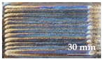 |
| 3 | 100 | 90 | Successive |  |
| 4 | 95 | 80 | Successive |  |
| 5 | 95 | 100 | Successive | 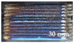 |
| 6 | 95 | 90 | Long-edge | 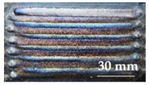 |
| 7 | 95 | 90 | Short-edge | 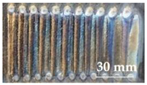 |
| No. | Simulated Stress Values | A | B | C | D | E | |||||
|---|---|---|---|---|---|---|---|---|---|---|---|
| σ /MPa | σx /MPa | σy /MPa | σx /MPa | σy /MPa | σx /MPa | σy /MPa | σx /MPa | σy /MPa | σx /MPa | σy /MPa | |
| 1 | 354 | 233 | 194 | 206 | 186 | 272 | 211 | 269 | 208 | 26 | 213 |
| 2 | 439 | 321 | 257 | 303 | 238 | 347 | 235 | 348 | 286 | 331 | 279 |
| 4 | 486 | 338 | 258 | 323 | 252 | 388 | 355 | 411 | 376 | 379 | 335 |
| 5 | 471 | 290 | 241 | 225 | 190 | 315 | 249 | 310 | 260 | 292 | 245 |
| 6 | 387 | 125 | 82 | 112 | 86 | 130 | 89 | 137 | 104 | 123 | 99 |
| 7 | 673 | 517 | 443 | 506 | 374 | 525 | 460 | 505 | 446 | 509 | 442 |
Publisher’s Note: MDPI stays neutral with regard to jurisdictional claims in published maps and institutional affiliations. |
© 2022 by the authors. Licensee MDPI, Basel, Switzerland. This article is an open access article distributed under the terms and conditions of the Creative Commons Attribution (CC BY) license (https://creativecommons.org/licenses/by/4.0/).
Share and Cite
Lai, Y.; Yue, X.; Yue, W. A Study on the Residual Stress of the Co-Based Alloy Plasma Cladding Layer. Materials 2022, 15, 5143. https://doi.org/10.3390/ma15155143
Lai Y, Yue X, Yue W. A Study on the Residual Stress of the Co-Based Alloy Plasma Cladding Layer. Materials. 2022; 15(15):5143. https://doi.org/10.3390/ma15155143
Chicago/Turabian StyleLai, Youbin, Xiang Yue, and Wenwen Yue. 2022. "A Study on the Residual Stress of the Co-Based Alloy Plasma Cladding Layer" Materials 15, no. 15: 5143. https://doi.org/10.3390/ma15155143
APA StyleLai, Y., Yue, X., & Yue, W. (2022). A Study on the Residual Stress of the Co-Based Alloy Plasma Cladding Layer. Materials, 15(15), 5143. https://doi.org/10.3390/ma15155143