
Study on Characteristics for Reaming Titanium Alloy Ti6Al4V with Two Kinds of Cemented-Carbide Groove Reamers


Abstract
:1. Introduction
2. Materials and Methods
2.1. Experimental Equipment
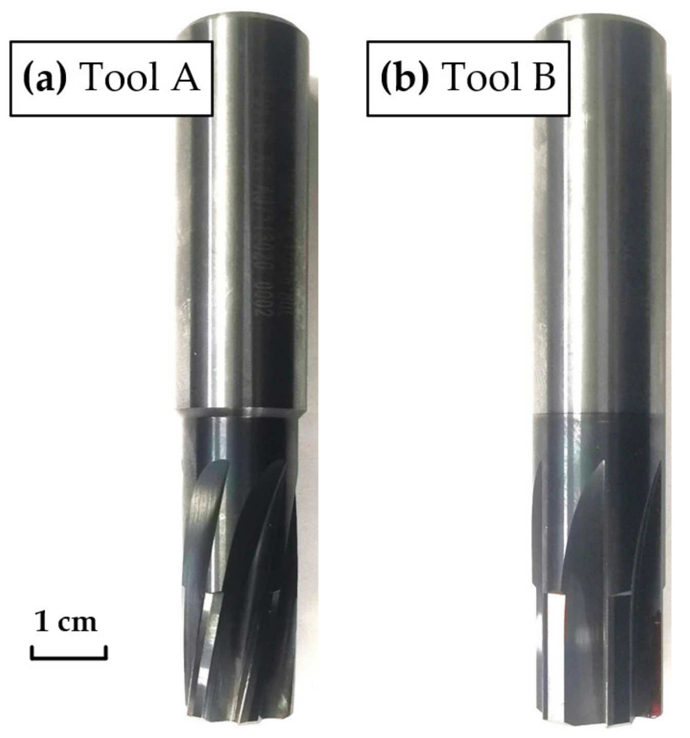
2.2. Tools and Workpiece Material
2.3. Testing Methods
3. Results and Discussion
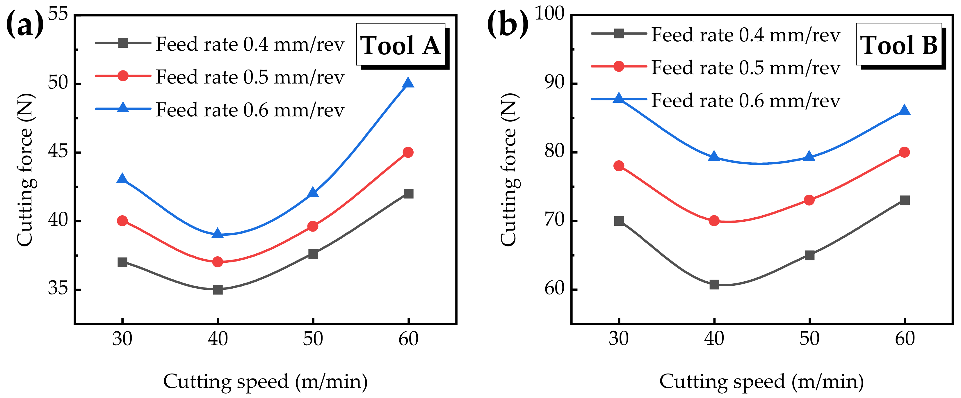
3.1. Cutting Force
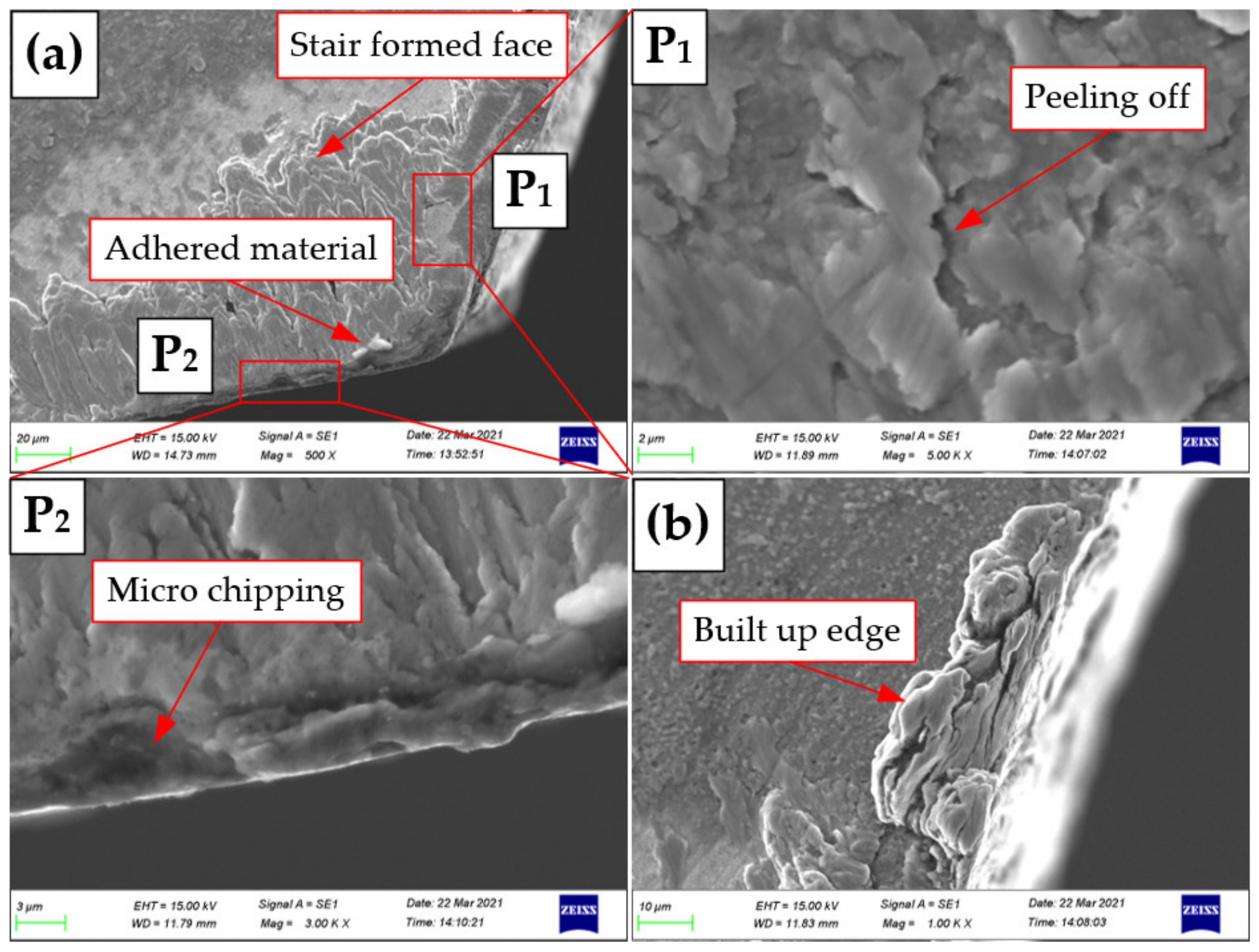
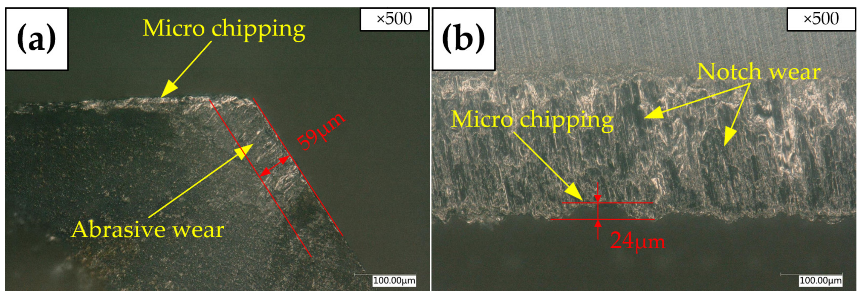
3.2. Tool Wear
3.3. Surface Quality
3.3.1. Surface Topography
3.3.2. Surface Roughness
3.4. Geometric Accuracy Error
3.4.1. Hole Diameter
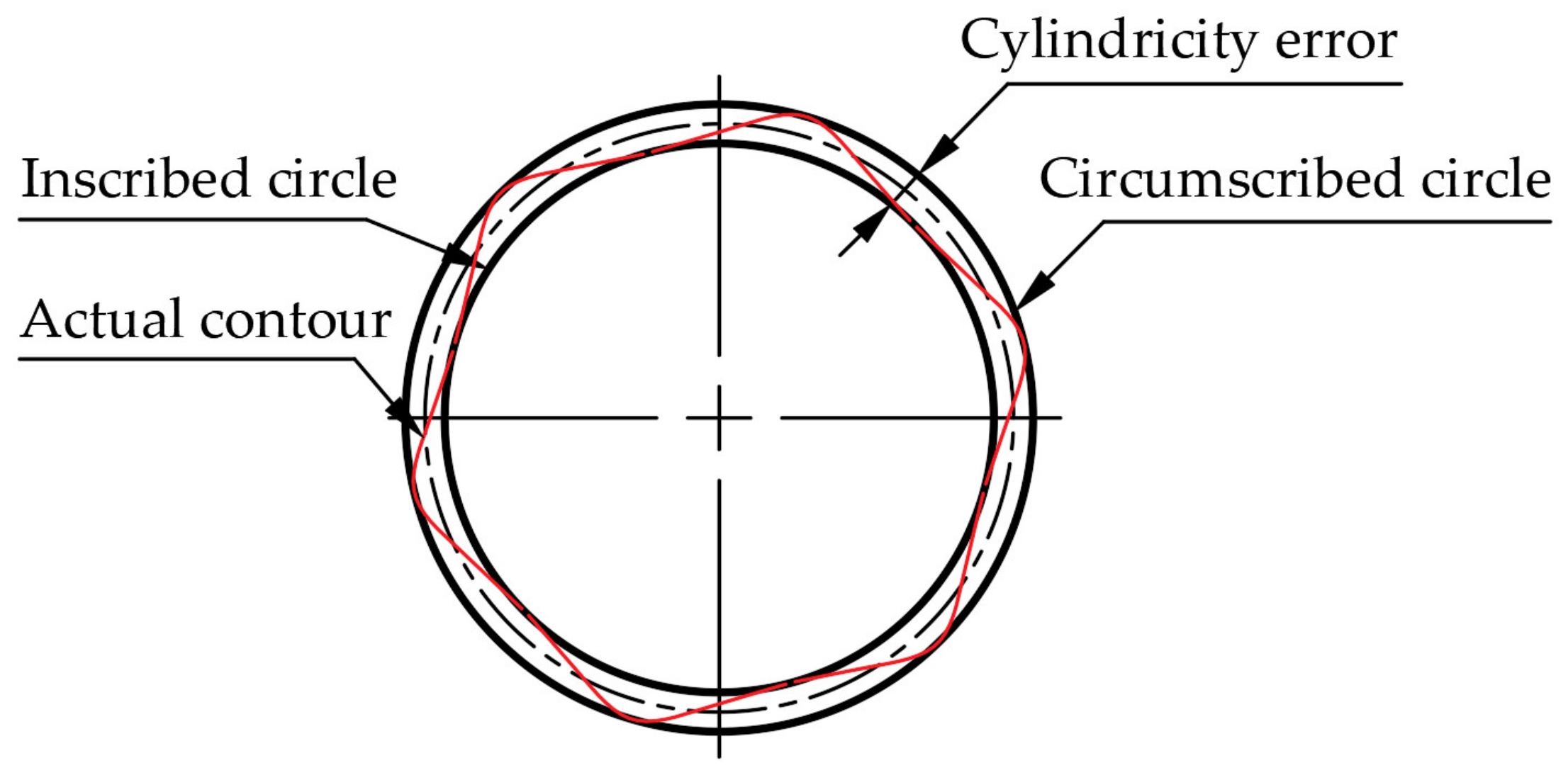
3.4.2. Cylindricity
4. Conclusions
- (1)
- Due to the groove structure, the shear mechanism occurs in the axial and radial direction for the right-hand reamer Tool A, while it merely occurs in the radial direction for the straight groove reamer Tool B, leading to the cutting force of the right-hand reamer Tool A being smaller than that of the straight groove reamer Tool B.
- (2)
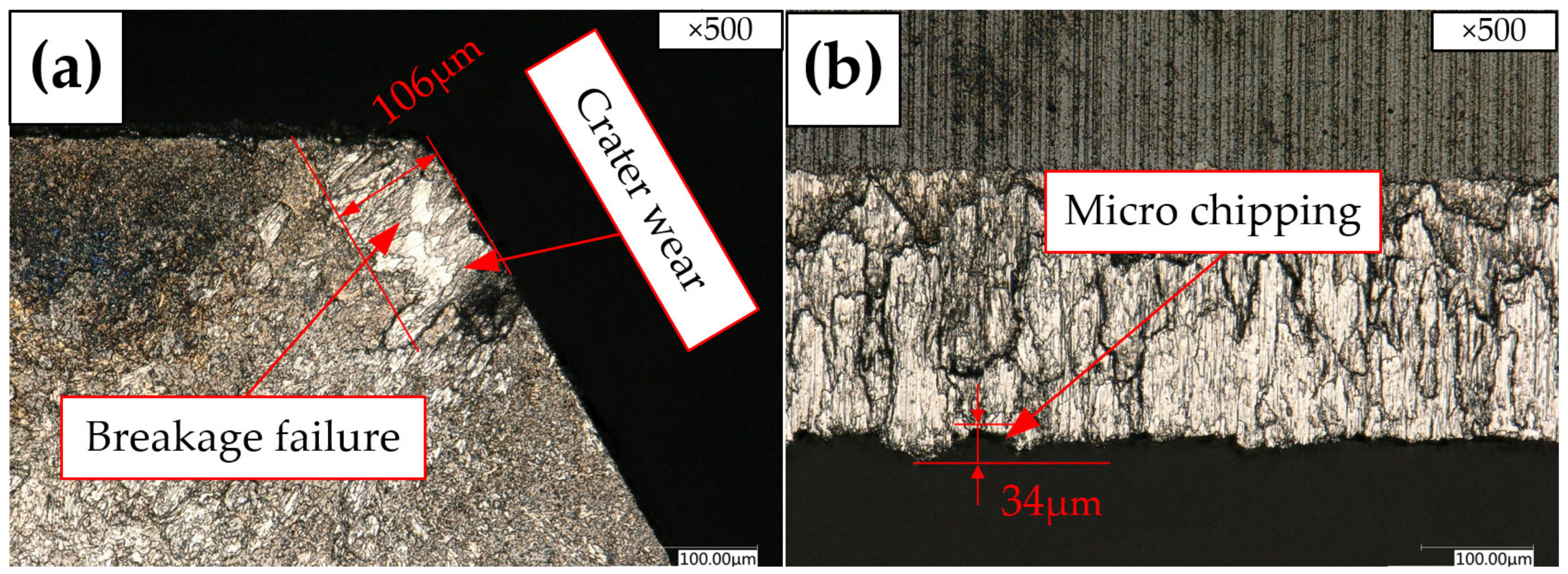
- Micro-chipping and material adhesion appear on the rake face of the right-hand reamer Tool A, while serious damage failure occurs on one cutting edge of the straight groove reamer Tool B. The wear of the margin plays an important role in determining the quality of the machined surface.
- (3)
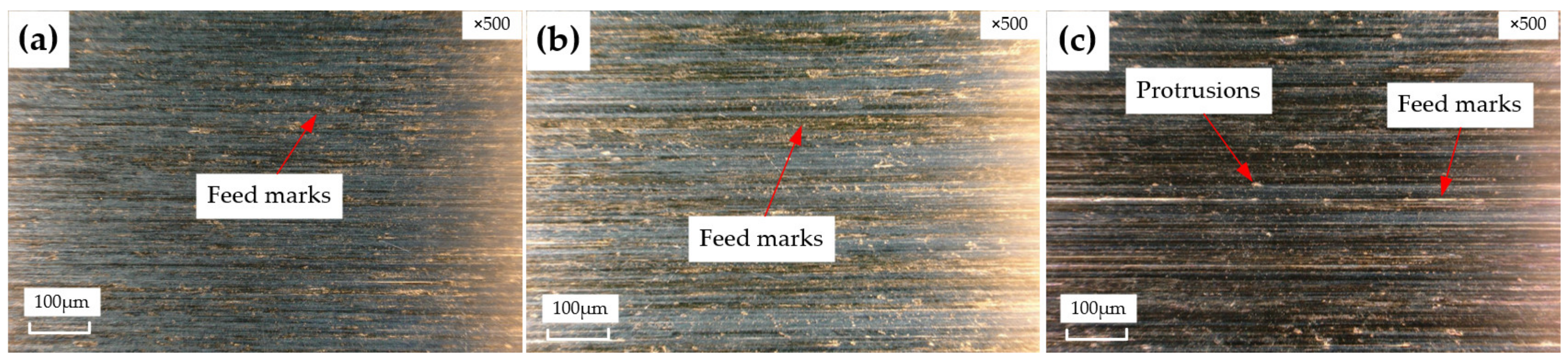
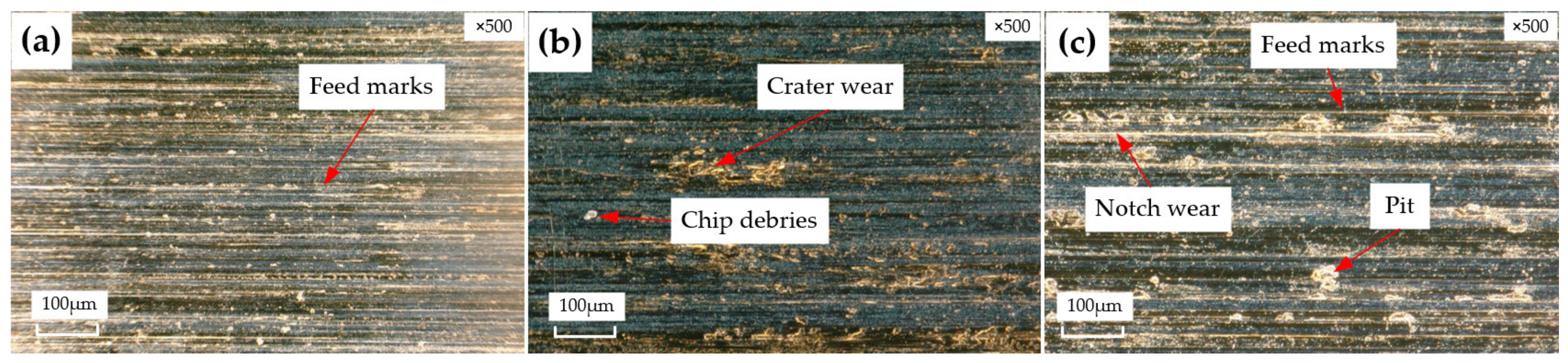
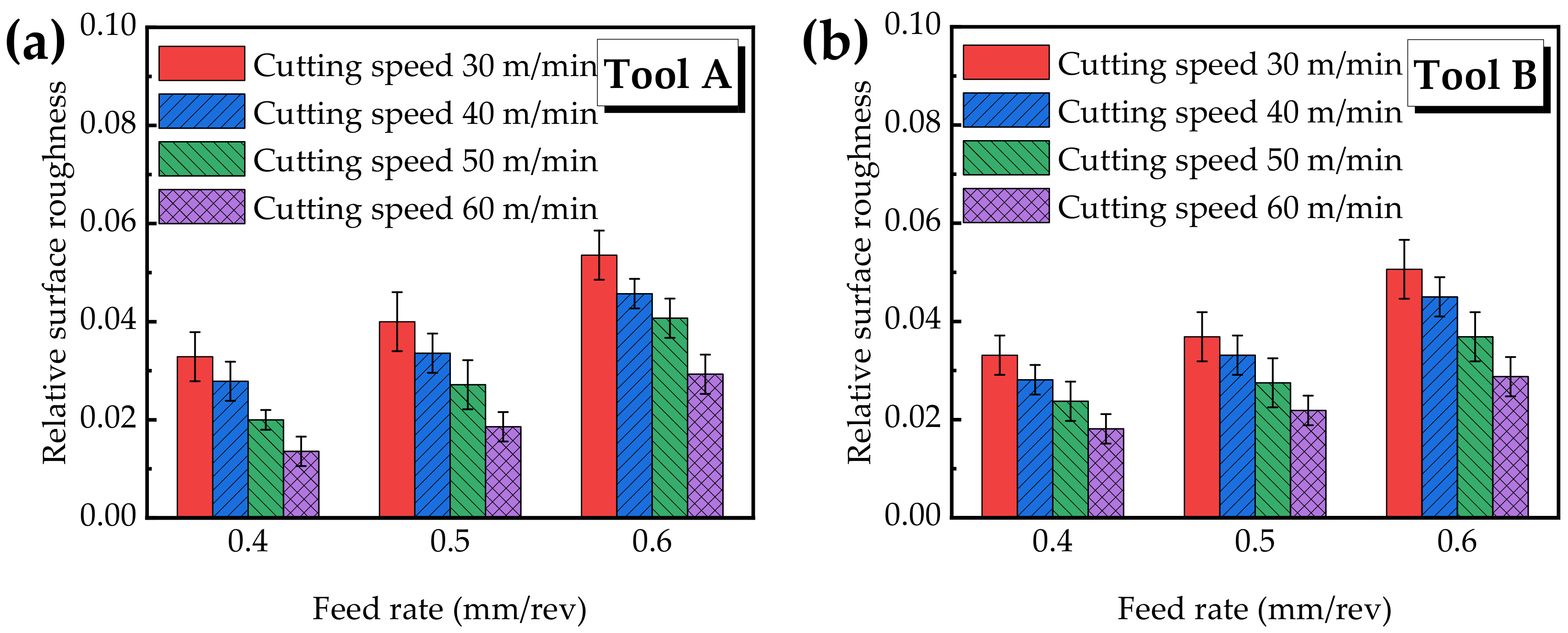
- The topography is better machined by the right-hand reamer Tool A compared to the straight groove reamer Tool B. In order to obtain lower surface roughness, a combination of a cutting speed of 60 m/min and a feed rate of 0.4 mm/rev should be selected.
- (4)
- With different cutting parameters, the holes machined by the right-hand reamer Tool A have a lower hole diameter deviation. The combination of a cutting speed of 40 m/min and a feed rate 0.4 mm/rev could achieve a high geometric accuracy of cylindricity, and the holes machined by the right-hand reamer Tool A show better cylindricity.
Author Contributions
Funding
Institutional Review Board Statement
Informed Consent Statement
Data Availability Statement
Conflicts of Interest
References
- Ke, X.; Wu, W.; Wang, C.; Yu, Y.; Zhong, B.; Wang, Z.; Wang, T.; Fu, J.; Guo, J. Material Removal and Surface Integrity Analysis of Ti6Al4V Alloy after Polishing by Flexible Tools with Different Rigidity. Materials 2022, 15, 1642. [Google Scholar] [CrossRef] [PubMed]
- Chen, G.; Ren, C.; Zou, Y.; Qin, X.; Lu, L.; Li, S. Mechanism for material removal in ultrasonic vibration helical milling of Ti6Al4V alloy. Int. J. Mach. Tools Manuf. 2018, 138, 1–13. [Google Scholar] [CrossRef]
- Abbas, A.T.; Al Bahkali, E.A.; Alqahtani, S.M.; Abdelnasser, E.; Naeim, N.; Elkaseer, A. Fundamental Investigation into Tool Wear and Surface Quality in High-Speed Machining of Ti6Al4V Alloy. Materials 2021, 14, 7128. [Google Scholar] [CrossRef] [PubMed]
- Zhang, Y.; Lee, Y.J.; Chang, S.; Chen, Y.; Bai, Y.; Zhang, J.; Wang, H. Microstructural modulation of TiAl alloys for controlling ultra-precision machinability. Int. J. Mach. Tools Manuf. 2022, 174, 103851. [Google Scholar] [CrossRef]
- De Chiffre, L.; Tosello, G.; Píška, M.; Müller, P. Investigation on capability of the reaming process using minimal quantity lubrication. CIRP J. Manuf. Sci. Technol. 2009, 2, 47–54. [Google Scholar] [CrossRef] [Green Version]
- Geng, D.; Zhang, D.; Li, Z.; Liu, D. Feasibility study of ultrasonic elliptical vibration-assisted reaming of carbon fiber reinforced plastics/titanium alloy stacks. Ultrasonics 2017, 75, 80–90. [Google Scholar] [CrossRef] [PubMed]
- Saketi, S.; Odelros, S.; Östby, J.; Olsson, M. Experimental study of wear mechanisms of cemented carbide in the turning of Ti6Al4V. Materials 2019, 12, 2822. [Google Scholar] [CrossRef] [PubMed] [Green Version]
- Li, H.; He, G.; Qin, X.; Wang, G.; Lu, C.; Gui, L. Tool wear and hole quality investigation in dry helical milling of Ti-6Al-4V alloy. Int. J. Adv. Manuf. Technol. 2014, 71, 1511–1523. [Google Scholar] [CrossRef]
- Sekar, K.V.; Gobivel, K.; Goutham, G.R.; Elangovan, P.P.; Babu, N.N. Cutting forces and tool wear studies on machining of Hastelloy X. Mater. Today Proc. 2022, 62, 852–857. [Google Scholar] [CrossRef]
- Melo, T.F.L.; Filho, S.L.M.R.; Arruda, M.; Brandão, L.C. Analysis of the surface roughness, cutting efforts, and form errors in bore reaming of hardened steel using a statistical approach. Measurement 2018, 134, 845–854. [Google Scholar] [CrossRef]
- Bezerra, A.; Machado, A.; Souza, A.; Ezugwu, E. Effects of machining parameters when reaming aluminium-silicon (SAE 322) alloy. J. Mater. Process. Technol. 2001, 112, 185–198. [Google Scholar] [CrossRef]
- Zhu, Z.; Sui, S.; Sun, J.; Li, J.; Li, Y. Investigation on performance characteristics in drilling of Ti6Al4V alloy. Int. J. Adv. Manuf. Technol. 2017, 93, 651–660. [Google Scholar] [CrossRef]
- Schützer, K.; Roth, M.; Abele, E.; Hauer, T. Experimental investigation of hole quality during reaming applications using multi-blade tools. J. Braz. Soc. Mech. Sci. Eng. 2014, 36, 797–806. [Google Scholar] [CrossRef]
- Yan, X.; Li, B.; Li, J.; Yang, L. Analysis of the machining characteristics in reaming AlSi12 alloy with PCD reamer. Int. J. Adv. Manuf. Technol. 2013, 69, 2387–2399. [Google Scholar] [CrossRef]
- Li, C.; Zha, J.; Chen, Y. Geometrical shape and dimension errors and surface roughness of stepped holes in a beryllium bronze-aluminum alloy joint produced by forming reamer. Int. J. Adv. Manuf. Technol. 2021, 117, 3029–3039. [Google Scholar] [CrossRef]
- Xu, J.; Li, C.; Chen, M.; El Mansori, M.; Davim, J.P. On the analysis of temperatures, surface morphologies and tool wear in drilling CFRP/Ti6Al4V stacks under different cutting sequence strategies. Compos. Struct. 2019, 234, 111708. [Google Scholar] [CrossRef]
- Jianxin, D.; Yousheng, L.; Wenlong, S. Diffusion wear in dry cutting of Ti-6Al-4V with WC/Co carbide tools. Wear 2008, 265, 1776–1783. [Google Scholar] [CrossRef]
- Zhang, S.; Li, J.F.; Deng, J.X.; Li, Y.S. Investigation on diffusion wear during high-speed machining Ti-6Al-4V alloy with straight tungsten carbide tools. Int. J. Adv. Manuf. Technol. 2008, 44, 17–25. [Google Scholar] [CrossRef]
- Nouari, M.; Makich, H. Experimental investigation on the effect of the material microstructure on tool wear when machining hard titanium alloys: Ti-6Al-4V and Ti-555. Int. J. Refract. Met. Hard Mater. 2013, 41, 259–269. [Google Scholar] [CrossRef]
- Zhang, H.; Dang, J.; Ming, W.; Xu, X.; Chen, M.; An, Q. Cutting responses of additive manufactured Ti6Al4V with solid ceramic tool under dry high-speed milling processes. Ceram. Int. 2020, 46, 14536–14547. [Google Scholar] [CrossRef]
- Chevrier, P.; Tidu, A.; Bolle, B.; Cezard, P.; Tinnes, J. Investigation of surface integrity in high speed end milling of a low alloyed steel. Int. J. Mach. Tools Manuf. 2003, 43, 1135–1142. [Google Scholar] [CrossRef]
- Sima, M.; Özel, T. Modified material constitutive models for serrated chip formation simulations and experimental validation in machining of titanium alloy Ti-6Al-4V. Int. J. Mach. Tools Manuf. 2010, 50, 943–960. [Google Scholar] [CrossRef]
- Li, A.; Zang, J.; Zhao, J. Effect of cutting parameters and tool rake angle on the chip formation and adiabatic shear characteristics in machining Ti-6Al-4V titanium alloy. Int. J. Adv. Manuf. Technol. 2020, 107, 3077–3091. [Google Scholar] [CrossRef]
- Arrazola, P.-J.; Garay, A.; Iriarte, L.-M.; Armendia, M.; Marya, S.; Le Maître, F. Machinability of titanium alloys (Ti6Al4V and Ti555.3). J. Mater. Process. Technol. 2009, 209, 2223–2230. [Google Scholar] [CrossRef] [Green Version]
- Cotterell, M.; Byrne, G. Dynamics of chip formation during orthogonal cutting of titanium alloy Ti-6Al-4V. CIRP Ann. 2008, 57, 93–96. [Google Scholar] [CrossRef]
- Özbek, N.A.; Çiçek, A.; Gülesin, M.; Özbek, O. Investigation of the effects of cryogenic treatment applied at different holding times to cemented carbide inserts on tool wear. Int. J. Mach. Tools Manuf. 2014, 86, 34–43. [Google Scholar] [CrossRef]
- Sharman, A.; Dewes, R.C.; Aspinwall, D.K. Tool life when high speed ball nose end milling Inconel 718™. J. Mater. Process. Technol. 2001, 118, 29–35. [Google Scholar] [CrossRef]
- Dhar, N.R.; Islam, S.; Kamruzzaman, M.; Paul, S. Wear behavior of uncoated carbide inserts under dry, wet and cryogenic cooling conditions in turning C-60 steel. J. Braz. Soc. Mech. Sci. Eng. 2006, 28, 146–152. [Google Scholar] [CrossRef] [Green Version]
- Graves, A.; Norgren, S.; Wan, W.; Singh, S.; Kritikos, M.; Xiao, C.; Crawforth, P.; Jackson, M. On the mechanism of crater wear in a high strength metastable beta titanium alloy. Wear 2021, 484–485, 203998. [Google Scholar] [CrossRef]
- Hatt, O.; Lomas, Z.; Thomas, M.; Jackson, M. The effect of titanium alloy chemistry on machining induced tool crater wear characteristics. Wear 2018, 408–409, 200–207. [Google Scholar] [CrossRef]
- D’Errico, G.E.; Calzavarini, R. Advanced ceramic tools: An experimental assessment in turning tests. J. Mater. Process. Technol. 1995, 54, 34–39. [Google Scholar] [CrossRef]
- Zou, B.; Chen, M.; Huang, C.; An, Q. Study on surface damages caused by turning NiCr20TiAl nickel-based alloy. J. Mater. Process. Technol. 2009, 209, 5802–5809. [Google Scholar] [CrossRef]
- Chan, K.; Cheung, C.; Ramesh, M.; Lee, W.; To, S. A theoretical and experimental investigation of surface generation in diamond turning of an Al6061/SiCp metal matrix composite. Int. J. Mech. Sci. 2001, 43, 2047–2068. [Google Scholar] [CrossRef]
- Matras, A.; Zębala, W.; Machno, M. Research and Method of Roughness Prediction of a Curvilinear Surface after Titanium Alloy Turning. Materials 2019, 12, 502. [Google Scholar] [CrossRef] [Green Version]
- Jinlong, W.; Wenjie, P.; Jing, Y.; Jingsi, W.; Mingchao, D.; Yuanliang, Z. Effect of surface roughness on the fatigue failure and evaluation of TC17 titanium alloy. Mater. Sci. Technol. 2021, 37, 301–313. [Google Scholar] [CrossRef]
- Wang, Z.; Li, H.; Yu, T. Study on Surface Integrity and Surface Roughness Model of Titanium Alloy TC21 Milling Considering Tool Vibration. Appl. Sci. 2022, 12, 4041. [Google Scholar] [CrossRef]
- Ramesh, S.; Karunamoorthy, L.; Palanikumar, K. Fuzzy Modeling and Analysis of Machining Parameters in Machining Titanium Alloy. Mater. Manuf. Process. 2008, 23, 439–447. [Google Scholar] [CrossRef]
- More, A.S.; Jiang, W.; Brown, W.; Malshe, A.P. Tool wear and machining performance of cBN–TiN coated carbide inserts and PCBN compact inserts in turning AISI 4340 hardened steel. J. Mater. Process. Technol. 2006, 180, 253–262. [Google Scholar] [CrossRef]
- Akkuş, H.; Yaka, H. Experimental and statistical investigation of the effect of cutting parameters on surface roughness, vibration and energy consumption in machining of titanium 6Al-4V ELI (grade 5) alloy. Measurement 2020, 167, 108465. [Google Scholar] [CrossRef]
- Sur, G.; Motorcu, A.R.; Nohutçu, S. Single and multi-objective optimization for cutting force and surface roughness in peripheral milling of Ti6Al4V using fixed and variable helix angle tools. J. Manuf. Process. 2022, 80, 529–545. [Google Scholar] [CrossRef]
- Bhise, V.Y.; Jogi, B.F. Effect of cutting speed and feed on surface roughness in dry turning of Inconel X-750. Mater. Today Proc. 2022, 61, 587–592. [Google Scholar] [CrossRef]
- Bono, M.; Ni, J. The effects of thermal distortions on the diameter and cylindricity of dry drilled holes. Int. J. Mach. Tools Manuf. 2001, 41, 2261–2270. [Google Scholar] [CrossRef]


| Item | Tool A | Tool B |
|---|---|---|
| Diameter | 14.018 mm | 16.018 mm |
| Length of cut | 15 mm | 15 mm |
| Length of flute | 30 mm | 30 mm |
| Direction of flute | Right | Straight |
| Number of flutes | 6 | 6 |
| Rake angle | 8° | 8° |
| Helix angle | 12° | 0° |
| First clearance angle | 10° | 10° |
| Second clearance angle | 25° | 25° |
| Margin | 0.2 mm | 0.2 mm |
| Clamping diameter | 16 mm | 16 mm |
| Length overall | 80 mm | 80 mm |
| Element | Ti | Al | V | Fe | C | N | H | O |
|---|---|---|---|---|---|---|---|---|
| wt% | Base | 5.5~6.75 | 3.5~4.5 | <0.25 | <0.08 | <0.05 | <0.01 | <0.2 |
| Number | Feed Rate (mm/rev) | Cutting Speed (m/min) |
|---|---|---|
| #1 | 0.4 | 30 |
| #2 | 0.4 | 40 |
| #3 | 0.4 | 50 |
| #4 | 0.4 | 60 |
| #5 | 0.5 | 30 |
| #6 | 0.5 | 40 |
| #7 | 0.5 | 50 |
| #8 | 0.5 | 60 |
| #9 | 0.6 | 30 |
| #10 | 0.6 | 40 |
| #11 | 0.6 | 50 |
| #12 | 0.6 | 60 |
Publisher’s Note: MDPI stays neutral with regard to jurisdictional claims in published maps and institutional affiliations. |
© 2022 by the authors. Licensee MDPI, Basel, Switzerland. This article is an open access article distributed under the terms and conditions of the Creative Commons Attribution (CC BY) license (https://creativecommons.org/licenses/by/4.0/).
Share and Cite
Zhang, Y.; Wang, Y.; Han, Z. Study on Characteristics for Reaming Titanium Alloy Ti6Al4V with Two Kinds of Cemented-Carbide Groove Reamers. Materials 2022, 15, 5027. https://doi.org/10.3390/ma15145027
Zhang Y, Wang Y, Han Z. Study on Characteristics for Reaming Titanium Alloy Ti6Al4V with Two Kinds of Cemented-Carbide Groove Reamers. Materials. 2022; 15(14):5027. https://doi.org/10.3390/ma15145027
Chicago/Turabian StyleZhang, Yongqiang, Yongguo Wang, and Zhanlong Han. 2022. "Study on Characteristics for Reaming Titanium Alloy Ti6Al4V with Two Kinds of Cemented-Carbide Groove Reamers" Materials 15, no. 14: 5027. https://doi.org/10.3390/ma15145027
APA StyleZhang, Y., Wang, Y., & Han, Z. (2022). Study on Characteristics for Reaming Titanium Alloy Ti6Al4V with Two Kinds of Cemented-Carbide Groove Reamers. Materials, 15(14), 5027. https://doi.org/10.3390/ma15145027