Abstract
The cable-stayed suspension bridge is one type of bridge that has been increasingly applied to bridge engineering, especially in cross-sea projects. However, the complex combined system of this type of bridge makes it quite difficult for researchers to make a quick decision of the parameter values during the design stage. The Hellinger–Reissner method is applied here to analyze the deformation and force of the structural members in the bridge. The advantage of this method is that the solving of deformation and force is independent of each other, which would enhance the accuracy of the final results. Different load conditions are also considered in the analysis. The results from the present method are compared with test results and finite element analysis, and show good agreements. It implies that the Hellinger–Reissner is a comparatively more efficient method to help designers choose the key parameters for cable-stayed suspension bridges.
1. Introduction
The cable-stayed suspension bridge is a combination of the cable-stayed system and the suspension system [1]. The structural members in the cable-stayed suspension bridge are introduced in Figure 1. Compared with suspension bridges, the cable-stayed suspension bridges have higher structural rigidity [1,2]. Compared with cable-stayed bridges, the cable-stayed suspension bridge provides better stability because of the lower compressive force caused by bridge decks. Furthermore, it has a lower cost than a suspension bridge with the same bridge span. Hence, the cable-stayed suspension bridge is an excellent solution for long-span bridges across the sea for structural, economic, and practical reasons [1,2,3].
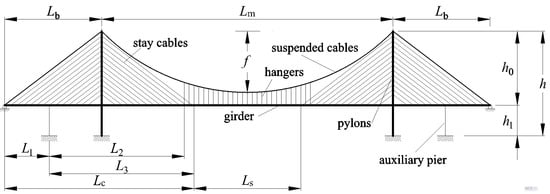
Figure 1.
Structural members in the cable-stayed suspension bridge.
There has been a large amount of research work on cable-stayed bridges and suspension bridges, including analyses of static, dynamic, linear, and nonlinear behaviors [4,5,6,7,8,9,10,11,12,13,14,15]. However, very few analyses have been conducted on the combined cable-stayed suspension bridges. Gimsing [1] has introduced the history and development of this type of bridge and provided detailed description of the two categories of this combined system: Roebling’s structural system and Dichinger’s structural system. Sun et al. [2] presented a four-step approach for determining the finished dead load state of a cable-stayed suspension bridge during the design stage by combining a finite element analysis with an iterative numerical method. Konstantakopoulos and Michaltsos [16] presented a mathematical model to analyze the nonlinear behavior of this type of bridge. Experimental investigation has also been applied to the study of the stability of the cable-stayed suspension bridge with orthotropic steel boxes [17]. Tests using models built in the laboratories were also conducted for optimizing the results of analyses [18,19].
The cable-stayed suspension bridges are still not as commonly constructed as cable-stayed bridges or suspension bridges. One of the major reasons is that there are interactions within the cable-stayed system and the suspension system in the design stage [1,16,20]. Analyses of complex combined cable systems are difficult because they not only require a large amount of work, but also could lead to significant errors. The design stage normally could be divided into several stages. First, in the early design stage, the bridge types along with corresponding material properties should be decided. The deformation and forces should be calculated to see if the chosen material and dimensional properties satisfy the early design stage requirements. Some approximate solutions such as the Ritz method have been presented to help in choosing parameters for the early design stage and solving the problems of engineering projects [21,22,23,24,25,26]. This method is highly efficient in obtaining the deformation of the members. In the Ritz method, the deformation hypothesis is the only hypothesis at the beginning of the computing process. Therefore, the disadvantage of the Ritz method is that the determination of the forces relies on the deformation solutions. The indirect computation of forces would lower the accuracy significantly. It is extremely important to obtain the key parameters of bridge members efficiently and correctly. Once the bridge type, the corresponding material, and dimensional properties are decided, the detailed structural analysis would be carried out, including more complicated loading combinations, loading types, dynamic behaviors, shear impacts, torsion effects, etc.
The Hellinger–Reissner variational principle is introduced here for the design of the cable-stayed suspension bridge. There are several parts included in the formulations of the Hellinger–Reissner functional [27,28]. The steps of this method mainly include raising the trial functions of the deformations and inner forces, applying the trial functions to the expression of the Hellinger–Reissner method, bringing in the deformation compatibility conditions, solving the equations, and obtaining the expressions for the deformation and inner forces. This method has been used by researchers to solve some engineering problems such as shells, beams, or new elements by incorporating with finite element analysis [29,30,31,32,33,34,35,36]. This is the first time that the Hellinger–Reissner method is applied for the analysis of the cable-stayed suspension bridge. The advantage of this method is that the expressions of the deformations and forces are independent of each other, instead of obtaining inner forces from the deformation. Therefore, it enhances the accuracy of forces to a large degree. This study also investigates the deformation and forces under different combinations of loads and sag-to-span ratios. The results show that the present method would help engineers make quick decisions on choosing the key parameters of the cable-stayed suspension bridge in the design stage.
2. Mechanical Model for Early Design Stage
The cable-stayed suspension bridge is a composite of many complex structural members. The following assumptions are suggested for the analysis in the conceptual design stage:
- (1)
- A symmetrical three-span cable-stayed suspension bridge with two pylons is taken as an example to analyze this type of bridge, as shown in Figure 1. The girder of the suspension and girder of the cable-stayed part are linked continuously. The fully floating deck system is considered in the analysis because of the presence of the auxiliary pier on the side span. This means that the pylon and girder in this case are not connected with any linkage vertically and longitudinally, but are still coupled in the lateral direction. Otherwise, without any auxiliary pier, the semi-floating deck system is applied here to simulate the additional linkage connecting the girder and pylon in the vertical direction.
- (2)
- The hangers and stay cables are distributed uniformly along the girder of the suspension and girder of the cable-stayed part, respectively. According to the membrane analogy, the force effects of the hangers and cables could be equivalent to those of a membrane between the catenary and girder. The rationality of this step is also supported by the results of a previous study [16]. As shown in Figure 2, the forces in the hangers can be replaced by a uniformly distributed load t1. Meanwhile, for the stay cables connecting the pylon and girder in the main span, the forces in the stay cables are equivalent to the uniformly distributed load t2 acting on the girder and t2T acting on the pylon. Similarly, in the side span, the forces in the stay cables are changed into a uniformly distributed load t3 acting on the girder and t3T acting on the pylon.
 Figure 2. Simplified combined cable-stayed suspension system.
 - (3)
- The live load caused by traffic and walking people could be replaced by a distributed load and concentrated load for static analysis. Meanwhile, the dead load of the bridge could also be equivalent to a uniformly distributed load. According to the superimposition principle, the load on the bridge can be assumed to be a combination of the distributed load q and concentrated load P, as shown in Figure 2. The different combinations of the distributed load q and concentrated load P are considered in the following calculation.
- (4)
- The axial force and deformation of either the main beam or pylon are neglected. Hence, the corresponding terms of the strain energy are also neglected. The effect of the shear force of the main beam and pylon is also not considered here. The strain energy of the auxiliary pier is neglected.
3. Analysis
With the mechanic model of the cable-stayed suspension system, the Hellinger–Reissner method was adopted to analyze the cable-stayed suspension bridge. The steps for data processing are as follows:
- (1)
- Trial functions of force and deformation should be proposed first with the coefficients to be solved. In this stage, the engineer is required to have the basic knowledge about how the structural members would deform with the load.
- (2)
- The trial functions are then applied to the Hellinger–Reissner principle to obtain the expression of the functional.
- (3)
- Partial differential equations for individual coefficients are obtained.
- (4)
- The deformation compatibility conditions are introduced to obtain the following equations.
- (5)
- By combining the equations from Step 3 and Step 4, the expressions of the coefficients are obtained by solving the equation sets.
- (6)
- By employing the expressions of the coefficients in the trial functions of force and deformation, the force and deformation expressions are obtained.
3.1. Girder
3.1.1. Hypotheses of Trial Functions
- (1)
- Force functions:
During the early design stage, engineers focus more on the forces and deformations in several vital cross-sectional areas. Higher-order functions would make the computing results more accurate but would make the computing procedures more complicated. Hence, the trial function of the bending moment of the cable-stayed part M1 uses the linear function hypotheses. Function M1 is divided into two parts, M11 and M12, to fit the force distribution with the support from the pylon and auxiliary pier. The hypothesis of the bending moment trial function of the cable-stayed part from 0 to L1 is named M11. The second part, L1–Lc, is named M12.
The suspension part uses a quadratic equation as the hypothesis of the bending moment function, M2.
- (2)
- Deformation function:
To simplify the computing procedures, deformation hypotheses are provided under the local coordinate system. The deformation function of the cable-stayed part w1 and that of the suspension part w2 both used quartic functions. Meanwhile, the deformation function w1 is a composite of two piecewise functions w11 and w12, corresponding to the force functions M11 and M12, respectively. The piecewise function w12 adopts the same function formation as w11 based on the coordinate translation.
3.1.2. Derivation of Equations
The hypotheses of the trial functions for the deformation and force of the girder are as follows:
- (1)
- For the cable-stayed part from 0 to L1, as shown in Figure 1, which is also from 0 to L1 in the local coordinate system, the deformation and force assumptions are described as follows:
- (2)
- For the cable-stayed part from L1 to Lc in the global coordinate system, as shown in Figure 1, the location in the local coordinate system ranges from 0 to L3. The deformation and force expressions are as follows:
where e3 and e4 are the coefficients to be solved.
- (3)
- For the suspension part from Lc to (Lc+Ls) in the global coordinate system, as shown in Figure 1, while the location is from 0 to Ls in the local coordinate system, the deformation and force expressions are as follows:
where L3 equals (Lc−L1), which is the distance from the auxiliary pier or the support of the pylon to the first hanger that does not cross the stay cables, and a1–a3 and e5–e6 are the coefficients to be solved.
Meanwhile, the continuous conditions should be satisfied because of the piecewise functions adopted in the deformation functions. The continuous conditions are described as w2|x=0 = w12|x=L3, (dw2/dx)|x=0 = (dw12/dx)|x=L3, and (d2w2/dx2)|x=0 = (d2w12/dx2)|x=L3.
Which gives the following solution of a1, a2, and a3:
Hence, only two coefficients, b1 and b2, are to be solved.
The piecewise functions of the force should also satisfy the continuous conditions M11|x= L1 = M12|x=0 and M12|x= L3 = M2|x=0.
The coefficients e4 and e6 are solved and eliminated by this step, which gives the following expressions for e4 and e6: e4 = e1L1 + e2, e4 = e1L1 + e2 + e3L3 – (e5Ls2)/4.
In summary, the expression of the girder part in the Hellinger–Reissner principle is as follows:
The simplified formation of the equation could be expressed as:
where , and the expressions for R1–R16 are listed in Appendix A.
3.2. Pylon
The pylon subjected to an external load is similar to a cantilever. The deformation uses a quartic function, while the force in the pylon is in the form of a quadratic function, which is as follows:
where c1, c2, e7, and e8 are the coefficients to be solved.
Hence, the flexural strain energy of the two pylons in the Hellinger–Reissner principle is expressed as:
where the expressions of U1 to U7 are described in Appendix A.
3.3. Main Cable of the Suspension Part
The tensile strain energy of the main cable is considered here, while the flexural strain energy of the main cable is neglected. The main cable was divided into two parts during the computing procedures: the main cable crossing the main span and the main cable crossing the side span. The parts were individually investigated.
The main cable crossing the main span was assumed to be a parabola. The shape of this part is described by the following expression in a local coordinate system in which the ‘0′ in the abscissa starts from the left pylon:
where f is the main cable sag and Lm is the length of the main span.
The shape of the main cable is similar to the deformation of a simply supported beam subjected to a load [37], as shown in Figure 3. Hence, the following relationship can be obtained according to the analogy between the main cable and the simply supported beam:
which gives the expression Hy(x) = M(x), where H is the horizontal component of the load in the main cable, q is the distributed load on the simply-supported beam, M is the bending moment distribution along the beam, α in Figure 3b is calculated as α = (L1 + L2 − Lb)/Lm = Lcs/Lm, where Lcs is the horizontal distance from the pylon to the first left hanger.

Figure 3.
Analogy between the main cable and a simply supported beam. (a) Main cable subjected to load. (b) Equivalent simply supported beam.
Hence, the bending moment for a simply supported beam with the same span can be calculated as:
When there is a live load on the girder, the main cable is subjected to the vertical membrane tension stress t1, as shown in Figure 2. The q0 and q1 in Figure 3b are computed as q0 = t1 and q1 = 0, respectively, according to which the horizontal component of the force in the main cable can be computed as:
Compared with suspension bridges, the horizontal component H here should be derived by multiplying H by a reduction factor (1 − 4α2). Consequently, the expression in the Hellinger–Reissner principle for the main cable crossing the midspan part is as follows:
The elongation of the main cable of the side-span part is dependent on the displacement of the pylon top. The displacement of the top of the pylon is expressed as ut=3h4c1+2h3c2.
The strain energy of the main cable corresponding to the left- and right-side span parts can be expressed as
where Emc is the Young’s modulus of the main cable, Amc is the cross-sectional area of the main cable, n is the ratio of the main cable sag to the span, which is calculated as n = f/Lm, Fmc is the axial force in the main cable of the side-span part, Δ is the elongation of the main cable, and φ is the angle between the girder and the main cable in the side span.
Hence, by combining Equations (19) and (20), the total strain energy of the main cable in the Hellinger–Reissner principle can be described as:
where the expressions for G1 to G4 are listed in Appendix A.
3.4. External Load Effects on the Bridge
According to the simplified mechanical model shown in Figure 2, the work done by the external load can be divided into the following parts: (1) the live load effect on the girder, (2) the membrane tensile load t1 caused by the hangers on the girder, (3) the membrane tensile load t1 from the hangers on the main cable, (4) the membrane tensile loads t2 and t3 from the stay cables on the girder, and (5) the membrane tensile loads t2T and t3T from the stay cables on the pylons. To simplify the computing procedures, an analysis of the work done by the external load was carried out in the global coordinate system.
- (1)
- Effects of live load on girder:
The live loads on the bridge could be the different combinations of q and P in Figure 2. Three load combinations are taken here as examples to show the expressions of the potential energy of the external load in the Hellinger–Reissner method. In addition, the different load combinations help to determine whether the hypotheses of the trial functions are appropriate.
In the case of the first type of load combination, the entire bridge is loaded with a uniformly distributed load q. The potential energy of the external load is expressed as:
In the second case of load combination, only the main span of the bridge is loaded with a uniformly distributed load q. Hence, the potential energy by the external load can be expressed as:
The third type of load condition is the uniformly distributed load q on the girder corresponding to the suspension part of the bridge. The expression of potential energy by the external load is:
The following term of the effect caused by the concentrated load P can be added to the abovementioned expressions, Equations (22)–(24), if the concentrated load is considered:
where the coefficients Q11, Q12, Q21, Q22, Q31, Q32, Qp1, and Qp2 are shown in Appendix A.
- (2)
- Effect of membrane tension t1 on girder:
The work done by the hanger membrane tension on the girder is negative, assuming that the positive displacement of the girder is vertically downward and the membrane tension on the girder is vertically upward.
where Lx is equal to (L1 + L2), and D1 and D2 are listed in Appendix A.
- (3)
- Effect of membrane tension t1 on main cable:
The displacement at the midspan of the main cable is Δf. The main cable under the load maintains a parabolic shape. Hence, the expression for the shape of the main cable after deformation is expressed as:
The deformation of the main cable at midspan under the live load is related to the deformation of the pylon top and elongation of the main cable. The two parts of the deformation are independent of each other. The effects of these two parts on the deformation of the main cable were derived by Chai et al. [37]:
where Δf1 is the deformation of the main cable caused by the displacement of the pylon top, Δf2 is the deformation of the main cable caused by the elongation of the main cable itself, and Δlmc is the amount of elongation of the main cable, expressed as:
which provides Δf = Δf1 + Δf2.
The expression of the work done by membrane tension t1 on the main cable is:
where the coefficients D3 to D5 are shown in Appendix A.
- (4)
- Effects of membrane tensions t2 and t3 on girder:
The calculation of the effects of stay cable membrane tensions t2 and t3 on the girder is similar to that of the hanger membrane tension on the girder and main cable. Hence, the expression for the effects of t2 and t3 on the girder can be expressed as:
where the coefficients D6 to D9 are shown in Appendix A.
- (5)
- Effects of membrane tensions t2T and t3T on the pylon:
It can be observed from Figure 4 that the relationship between the stay cable membrane tension on the girder and that on the pylon can be expressed as:
where θ is the stay cable inclination angle, as shown in Figure 4, d1 is the space between the stay cables on the girder, d2 is the space between the stay cables on the pylon, and the relationship between the three factors is cot(θ) = d1/d2 if the stay cables are parallel to each other.
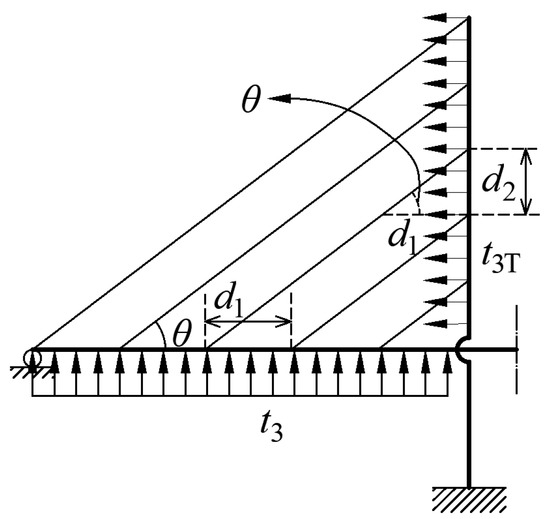
Figure 4.
Parameters of membrane tension for the stay cable.
The stay cable membrane tensions are uniformly distributed along the pylon. The work done by the membrane tensions t2T and t3T on the pylon is expressed as:
where hc1 and hc2 are the heights of the beginning and end points of the stay cables anchored on the pylon, which are equal to h1 and h, respectively, as shown in Figure 3, if the stay cable membrane tension is uniformly distributed along the pylon above the girder; the coefficients D10 to D13 are shown in Appendix A.
3.5. Total Potential Energy
According to each part of the potential energy explained above, the total potential energy of the system can be obtained as:
where πqi is the work done by the ith type of load condition on the girder.
where ξi is the ith element in the vector ξHR, and ξHR is expressed as:
To sum up, Equation (37) can be transformed into the following matrix equation:
where KHR and F could be expressed as:
3.6. Deformation Compatibility Conditions
The expressions for the coefficients can be obtained by solving Equation (38), but as a function of t1, t2, and t3. However, solutions for the coefficients have not yet been obtained at this step. Hence, deformation compatibility conditions shown in Figure 5 are introduced to derive the solutions for the coefficients.

Figure 5.
Deformation compatibility conditions between the stay cables and girder. (a) Displacement caused by elongation of stay cables. (b) Displacement caused by pylon deformation.
The first deformation compatibility condition in Figure 5a is that the midspan displacement of the girder is equal to that of the main cable if the elongation of the hanger is neglected.
The other deformation compatibility condition shown in Figure 5b is that the displacement of the stay cable is the same as the displacement of the girder at the point where the stay cable is anchored to the girder. Meanwhile, the stay cable displacement at this point is related to the elongation itself and the horizontal deformation of the pylon. These two deformation compatibility conditions are expressed as follows:
- (1)
- Side span:
- (2)
- Main span:
where x0 is the location on the abscissa of the stay cable anchored at the girder, and γ is the inclination angle of the stay cable, which is equal to θ when the stay cables are parallel to each other. If the sag effect of the stay cables is considered, the Young’s modulus of the stay cables can be adjusted or reduced according to the Ernst equation [38] if the initial tension of the stay cables is already known.
The membrane tension can be solved using Equations (39)–(41). Based on this, the solutions for the deformation of the structure members can be presented.
4. Verification
To carry out the verification of the presented method, the results from the finite element analysis and test are both compared with the presented H-R method. First, a cable-stayed suspension bridge with a 263 + 800 + 263 m span is introduced here [18,19]. The geometric parameters are presented in Figure 6. The pylon was made of Chinese C50 concrete. The total height of the pylon is 200 m. The girder of the cable-stayed part is also made of Chinese C50 concrete with a rectangular cross-section, whereas the girder of the suspension part is made of an aluminum alloy box. Meanwhile, the tensile strength value of both the stay cable and the main cable is 1600 MPa. The space between stay cables along the girder is 16 m, while the space along the pylon is 2–3 m. The space between the hangers along the girder is also 16 m. There is one auxiliary pier supporting each side span. Hence, a fully floating deck system is applied here, which means that the pylon and girder are not connected longitudinally along the girder or vertically along the pylon.

Figure 6.
Dimensional properties of the test model of the bridge (unit: m).
Researchers [18,19] have studied the structural behavior of this bridge by building a 1:100 bridge model in the laboratory. Both the finite element results and test results along with more detailed information are provided in the literature [18,19]. The software used in the finite element analysis is ANSYS. Both the beam and pylon were using the 3D BEAM4 elements. The hangers and the stay cables were using the LINK10 elements, which were set to be subjected to tensile force only. The geometric nonlinear analyses were performed.
The key parameters of the structural members are listed in Table 1.

Table 1.
Material properties.
The midspan deflection and the displacement of the top of the pylon were investigated using both tests and the finite element analysis by Du [18] and Wang [19]. The results are compared with the numerical data from the Hellinger–Reissner method. There are three types of load combinations in the comparison analysis. The first load combination, called load combination 1 here, involves a concentrated force P = 500 N on the midspan, as shown in Figure 7a. Another type of load combination, called load combination 2, is shown in Figure 7b and includes a concentrated force P = 250 N on the midspan and a distributed load q = 125 N/m along the suspension part. Figure 7c shows the third load combination, called load combination 3. It is composed of a concentrated force P = 250 N on the midspan and a distributed load q = 125 N/m along the main span.
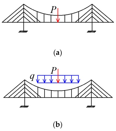
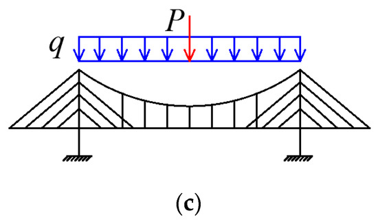
Figure 7.
Load combinations. (a) Load combination 1 (P = 500 N). (b) Load combination 2 (P = 250 N, q = 125 N/m). (c) Load combination 3 (P = 250 N, q = 125 N/m).
The comparison results are then shown in Figure 8. The ordinate of Figure 8a is the midspan deflection, while the ordinate in Figure 8b is the displacement of the top of the pylon. The positive direction is indicated by arrows in the figures.
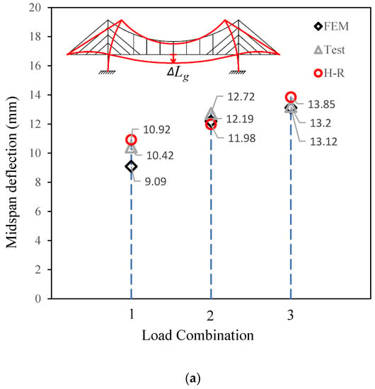
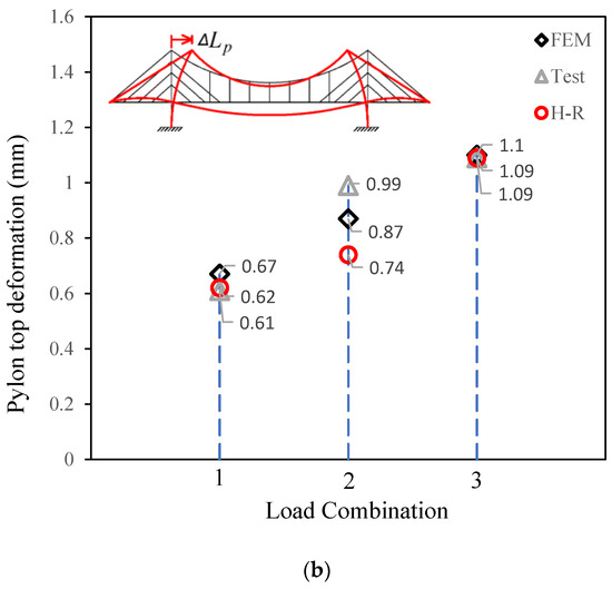
Figure 8.
Comparisons between different methods. (a) Comparison of midspan deflections. (b) Comparison of the pylon top deformation.
Figure 8a shows that the fitting among the results from the three methods is good for midspan deflection. The maximum gap is between the results from the Hellinger–Reissner method and the finite element method, with an error of 10% under load combination 1. Meanwhile, for the same type of load combination, the error between the test and the Hellinger–Reissner method is less than 5%.
For the top displacement of the pylon in Figure 8b, the maximum error, which is approximately 20%, occurs under load combination 2. The other two load combinations were in good agreement among the three types of methods. One of the reasons for this may be that the absolute values are small, which makes the comparative error much larger. The other reason could be explained as maybe there are some errors in the operation of the test based on the fact that the error between the finite element analysis and tests is also large. The third reason could be the hypothesis of deformation expression. The conduction of the H-R method requires the hypothesis of both the deformation expression and the force expression. Engineers should have certain experience to decide which expression to use at the early stage of analysis based on the H-R method. In addition, simplified evaluation would lead to errors in the results.
5. Sensitivity Analyses
The impact of the sag-to-span ratio on the deformation of the combined cable-stayed suspension bridge was then investigated. Jin et al. [39] provided the results from the finite element analysis of the deflection at the midspan and the displacement of the top of the pylon. The Hellinger–Reissner method was applied here with the same material properties and the same load condition mentioned in a published paper [39]. The corresponding data were obtained and compared with the finite element analysis. The span arrangement is illustrated in Figure 9. The length of the main span Lm is equal to twice the summation of ‘a’, ‘b’, ‘c’, and ‘d’. The side span Lb is equal to the summation of ‘d’, ‘c’, and ‘e’.

Figure 9.
Arrangement of dimensional properties.
Detailed values are listed in Table 2. There are five different types of span arrangements. The different types are named ‘A’, ‘B’, C’, ‘D’, and ‘E’. The sag-to-suspension ratio listed in the fifth column of Table 2 varies from 0.4 to 0.8.

Table 2.
Different dimensional arrangement.
As illustrated in Figure 10a, the comparison shows that the fitting of the midspan deflection is relatively good from the sag-to-suspension ratio of 0.4 to 0.8. The values of ΔLg from the two methods are almost the same for models A, D, and E, as shown in Figure 10a. The errors between the two methods are approximately 10% and 5%, respectively, in models B and C. The data points obtained from the Hellinger–Reissner method were fitted using linear and quadratic equations. As shown in Figure 10a, the r-square values for both expressions are close to 1. This also means that the distribution of the data points is in a very clear form of linear ascending.
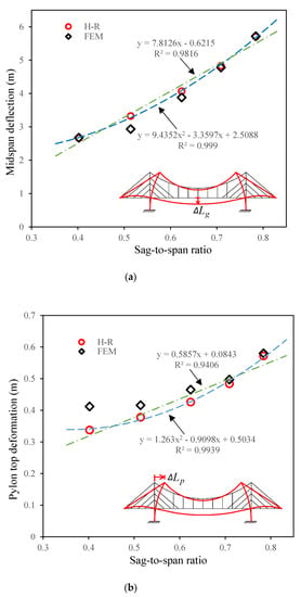
Figure 10.
Impact of sag-to-span ratio on deformation. (a) Midspan deflection changing with sag-to-span ratio. (b) Pylon top deformation changing with sag-to-span ratio.
The fitting of the top displacement of the pylon, ΔLp, is shown in Figure 10b. The errors between the Hellinger–Reissner method and the finite element analysis imply that the increasing of sag-to-suspension ratio improves the fitting between the two methods. The maximum discrepancy exists in the case of model A, where the error reaches 17%. It shows that the data points of the Hellinger–Reissner method were also fitted by the linear and quadratic equations with good fitting results.
6. Conclusions
The Hellinger–Reissner variational principle is introduced here to investigate the structural behavior of the combined cable-stayed suspension bridge. The procedures of the application of Hellinger–Reissner variational principle in the analysis of cable-stayed suspension bridge is described in detail, which consist of the hypotheses of the deformation, the hypotheses of the force expressions for the structural members, along with the boundary compatibility conditions to build the matrix equation. By solving the matrix equation, the coefficients of the deformation and force expressions are derived directly. The main works are described as follows:
(1) One case of the cable-stayed suspension bridge was analyzed and compared with finite element analysis and test results, and the comparisons showed good agreement. This means that the results from the Hellinger–Reissner method satisfy the requirements of the conceptual design stage.
(2) Parametric discussion including the sag-to-span ratio of the bridge was conducted, showing that the agreement between the Hellinger–Reissner results and the finite element analysis increases as the sag-to-span ratio goes up within the appropriate range.
(3) The Hellinger–Reissner method is efficient in solving the deformation and force of the members of bridges with a combined system. It could be used as a quick solution to help designers make decisions in the early design stage. Besides, it could also be used to verify the finite element analysis to reduce human errors.
7. Outlook
This article provides methodology for the early design stage of the combined cable-stayed suspension bridge. However, this methodology could be extended to some complicated problems during the state of serviceability, e.g., dynamic behavior, geometric nonlinearities of the suspension cables, and torsional effects. These problems could not be neglected when the bridge is in service state.
Author Contributions
Conceptualization, R.X. and J.C.; Data curation, Q.F., P.W. and J.L.; Investigation, Q.F. and D.W.; Methodology, Q.F., P.W., J.L., D.W., J.C. and R.X.; Supervision, R.X. and J.C.; Validation, Q.F. and P.W.; Writing—original draft, Q.F., P.W. and R.X.; Writing—review & editing, Q.F. and R.X.; Funding acquisition, R.X. All authors have read and agreed to the published version of the manuscript.
Funding
This research was funded by “Pioneer” and “Leading Goose” R&D Program of Zhejiang, grant number 2022C01143, National Natural Science Foundation of China, grant number 51478422.
Acknowledgments
The authors gratefully acknowledge the financial support from the “Pioneer” and “Leading Goose” R&D Program of Zhejiang (No. 2022C01143) and National Natural Science Foundation of China (Grant No. 51478422).
Conflicts of Interest
The authors declare no conflict of interest.
Nomenclature
| A | cross-section area |
| d | distance between stay cables |
| E | Young’s modulus |
| f | rise of the main cable |
| h | height of the pylon |
| I | inertia moment |
| M | function for bending moment |
| Lb | length of the side span |
| Lm | length of the main span |
| Ls | length of the suspension part |
| P | concentrated load on the bridge |
| q | uniformly distributed load on the bridge |
| t1 | membrane tension of hangers |
| t2 | membrane tension of stay cable on main span |
| t3 | membrane tension of stay cable on side span |
| w | function for deflection |
| Δf | elongation of the hanger |
| π | function for potential energy |
| θ | inclination angle of the stay cable |
Appendix A
The following expressions are provided for describing the procedures of the methodology.
Expressions for R1–R16:
Expressions for U1–U7:
Expressions for G1–G4:
Expressions for Q11–Q32:
Expressions for Qp1–Qp2:
Expressions for D1–D13:
References
- Gimsing, N.J. Cable Supported Bridges—Concept & Design; John Wiley & Sons: Chichester, UK, 1997. [Google Scholar]
- Sun, B.; Cai, C.S.; Xiao, R.C. Analysis strategy and parametric study of cable-stayed-suspension bridges. Adv. Struct. Eng. 2013, 16, 1081–1102. [Google Scholar] [CrossRef]
- Ito, M. Cable-Supported steel bridges: Design problems and solutions. J. Constr. Steel Res. 1996, 39, 69–84. [Google Scholar] [CrossRef]
- Ermopoulos, J.; Vlahinos, A.; Wang, Y.C. Stability analysis of cable-stayed bridges. Comput. Struct. 1992, 44, 1083–1089. [Google Scholar] [CrossRef]
- Khalil, M.S. Nonlinear analysis of cable-stayed bridges at ultimate load level. Can. J. Civ. Eng. 1996, 23, 1111–1117. [Google Scholar] [CrossRef]
- Oliveira, P.; Jose, J.; Reis, A.J. Simplified assessment of cable-stayed bridges buckling stability. Eng. Struct. 2016, 114, 93–103. [Google Scholar] [CrossRef]
- Hashemi, S.K.; Bradford, M.A.; Valipour, H.R. Dynamic response of cable-stayed bridge under blast load. Eng. Struct. 2016, 127, 719–736. [Google Scholar] [CrossRef]
- Peter, G.; Buckland, P.E. Increasing the load capacity of suspension bridges. J. Bridge Eng. 2003, 8, 288–296. [Google Scholar]
- Gwon, S.G.; Choi, D.H. Static and dynamic analyses of a suspension bridge with three-dimensionally curved main cables using a continuum model. Eng. Struct. 2018, 161, 250–264. [Google Scholar] [CrossRef]
- Xiao, X.; Xue, H.; Chen, B. Nonlinear model for the dynamic analysis of a time-dependent vehicle-cableway bridge system. Appl. Math. Model. 2021, 90, 1049–1068. [Google Scholar] [CrossRef]
- Adanur, S.; Gunaydin, M.; Altunişik, A.C.; Sevim, B. Construction stage analysis of Humber Suspension Bridge. Appl. Math. Model. 2012, 36, 5492–5505. [Google Scholar] [CrossRef]
- Irvine, H.M. Cable Structures; The MIT Press: Cambridge, UK, 1981. [Google Scholar]
- Chen, C.C.; Wu, W.H.; Chen, S.Y.; Lai, G. A novel tension estimation approach for elastic cables by elimination of complex boundary condition effects employing mode shape functions. Eng. Struct. 2018, 166, 152–166. [Google Scholar] [CrossRef]
- Bonopera, M.; Chang, K.C.; Chen, C.C.; Lin, T.K.; Tullini, N. Bending tests for the structural safety assessment of space truss members. Int. J. Space Struct. 2018, 33, 138–149. [Google Scholar] [CrossRef]
- Wu, W.H.; Chen, C.C.; Chen, Y.C.; Lai, G.; Huang, C.M. Tension determination for suspenders of arch bridge based on multiple vibration measurements concentrated at one end. Measurement 2018, 123, 254–269. [Google Scholar] [CrossRef]
- Konstantakopoulos, T.G.; Michaltsos, G.T. A mathematical model for a combined cable system of bridges. Eng. Struct. 2010, 32, 2717–2728. [Google Scholar] [CrossRef]
- Wang, F.; Lv, Z.D.; Gu, M.J.; Chen, Q.K.; Zhao, Z.; Luo, J. Experimental study on stability of orthotropic steel box girder of self-anchored suspension cable-stayed bridge. Thin-Walled Struct. 2021, 163, 107727. [Google Scholar] [CrossRef]
- Du, G.M. Analysis on the Structural Behavior of Large-Span Self-Anchored Cable-Stayed Suspension Bridge. Master’s Thesis, Dalian University of Technology, Dalian, China, 2006. [Google Scholar]
- Wang, H.L. Structure Properties Analysis and Experiment Study of Self-Anchored Cable-Stayed Suspension Bridge. Ph.D. Thesis, Dalian University of Technology, Dalian, China, 2006. [Google Scholar]
- Granata, M.F.; Longo, G.; Recupero, A.; Arici, M. Construction sequence analysis of long-span cable-stayed bridges. Eng. Struct. 2018, 174, 267–281. [Google Scholar] [CrossRef]
- Ding, Z. Natural Frequencies of Rectangular Plates Using a Set of Static Beam Functions in Rayleigh-Ritz Method. J. Sound Vib. 1996, 189, 81–87. [Google Scholar] [CrossRef]
- Wang, S. A Unified Timoshenko Beam B-Spline Rayleigh–Ritz Method for Vibration and Buckling Analysis of Thick And Thin Beams And Plates. Int. J. Numer. Methods Eng. 1997, 40, 473–491. [Google Scholar] [CrossRef]
- Xue, W.C.; Liu, S. Linear elastic and limit state solutions of beam string structures by the Ritz-method. Struct. Eng. Mech. 2010, 35, 67–82. [Google Scholar] [CrossRef]
- Kiani, Y. Analysis of FG-CNT reinforced composite conical panel subjected to moving load using Ritz method. Thin-Walled Struct. 2017, 119, 47–57. [Google Scholar] [CrossRef]
- Albas, S.D.; Ersoy, H.; Akgoz, B.; Civalek, O. Dynamic Analysis of a Fiber-Reinforced Composite Beam under a Moving Load by the Ritz Method. Mathematics 2021, 9, 1048. [Google Scholar]
- Belardi, V.G.; Fanelli, P.; Vivio, F. Elastic analysis of rectilinear orthotropic composite circular plates subject to transversal and in-plane load conditions using Ritz method. Compos. Struct. 2018, 199, 63–75. [Google Scholar] [CrossRef]
- Reissner, E. On a variational theorem in elasticity. J. Mathemactics Phys. 1950, 29, 90–95. [Google Scholar] [CrossRef]
- Reddy, J.N. Energy Principles and Variational Methods in Applied Mechanics; John Wiley & Sons, Inc.: Chichester, UK, 1984. [Google Scholar]
- Beltempo, A.; Balduzzi, G.; Alfano, G.; Auricchio, F. Analytical derivation of a general 2D non-prismatic beam model based on the Hellinger-Reissner principle. Eng. Struct. 2015, 101, 88–98. [Google Scholar] [CrossRef]
- Trinh, L.C.; Ojo, S.O.; Groh, R.M.J.; Weaver, P.M. A mixed inverse differential quadrature method for static analysis of constant- and variable-stiffness laminated beams based on Hellinger-Reissner mixed variational formulation. Int. J. Solids Struct. 2021, 210, 66–87. [Google Scholar] [CrossRef]
- Lee, Y.; Yoon, K.; Lee, P.S. Improving the MITC3 shell finite element by using the Hellinger–Reissner principle. Comput. Struct. 2012, 110, 93–106. [Google Scholar] [CrossRef]
- Auricchio, F.; Balduzzi, G.; Khoshgoftar, M.J.; Rahimi, G.; Sacco, E. Enhanced modeling approach for multilayer anisotropic plates based on dimension reduction method and Hellinger–Reissner principle. Compos. Struct. 2014, 118, 622–633. [Google Scholar] [CrossRef]
- Kikuchi, F.; Ando, Y. Rectangular Finite Element for Plate Bending Analysis Based on Hellinger-Reissner’s Variational Principle. J. Nucl. Sci. Technol. 1972, 9, 28–35. [Google Scholar] [CrossRef][Green Version]
- Auricchio, F.; Balduzzi, G.; Lovadina, C. The dimensional reduction modelling approach for 3D beams: Differential equations and finite-element solutions based on Hellinger–Reissner principle. Int. J. Solids Struct. 2013, 50, 4184–4196. [Google Scholar] [CrossRef]
- Qian, R.L. A modified Hellinger-Reissner variational functional including only two independent variables for large displacement of thin shallow shell. Appl. Math. Mech. 1997, 18, 663–670. [Google Scholar]
- Morley, L.S.D. Hellinger-Reissner principles for plate and shell finite elements. Int. J. Numer. Methods Eng. 1984, 20, 773–777. [Google Scholar] [CrossRef]
- Chai, S.B.; Xiao, R.C.; Sun, B. Deformation characteristics of main cable in suspension bridge caused by live load. J. Tongji Univ. (Nat. Sci.) 2012, 40, 1452–1457. [Google Scholar]
- Li, G.P. State revision method in nonlinear analysis of stay cable. J. Tongji Univ. (Nat. Sci.) 2000, 28, 1–4. [Google Scholar]
- Jin, G.S.; Yang, Z.J.; Liu, Y.H. Analysis of main design parameters of cable-stayed and suspension combined system bridge. Highway 2007, 3, 80–84. [Google Scholar]
Publisher’s Note: MDPI stays neutral with regard to jurisdictional claims in published maps and institutional affiliations. |
© 2022 by the authors. Licensee MDPI, Basel, Switzerland. This article is an open access article distributed under the terms and conditions of the Creative Commons Attribution (CC BY) license (https://creativecommons.org/licenses/by/4.0/).