
Insight into Point Defects and Complex Defects in β-Mo2C and Carbide Evolution from First Principles

Abstract
:1. Introduction
2. Calculation Details
3. Results
3.1. Intrinsic Defects
3.1.1. Formation Energy and Stability
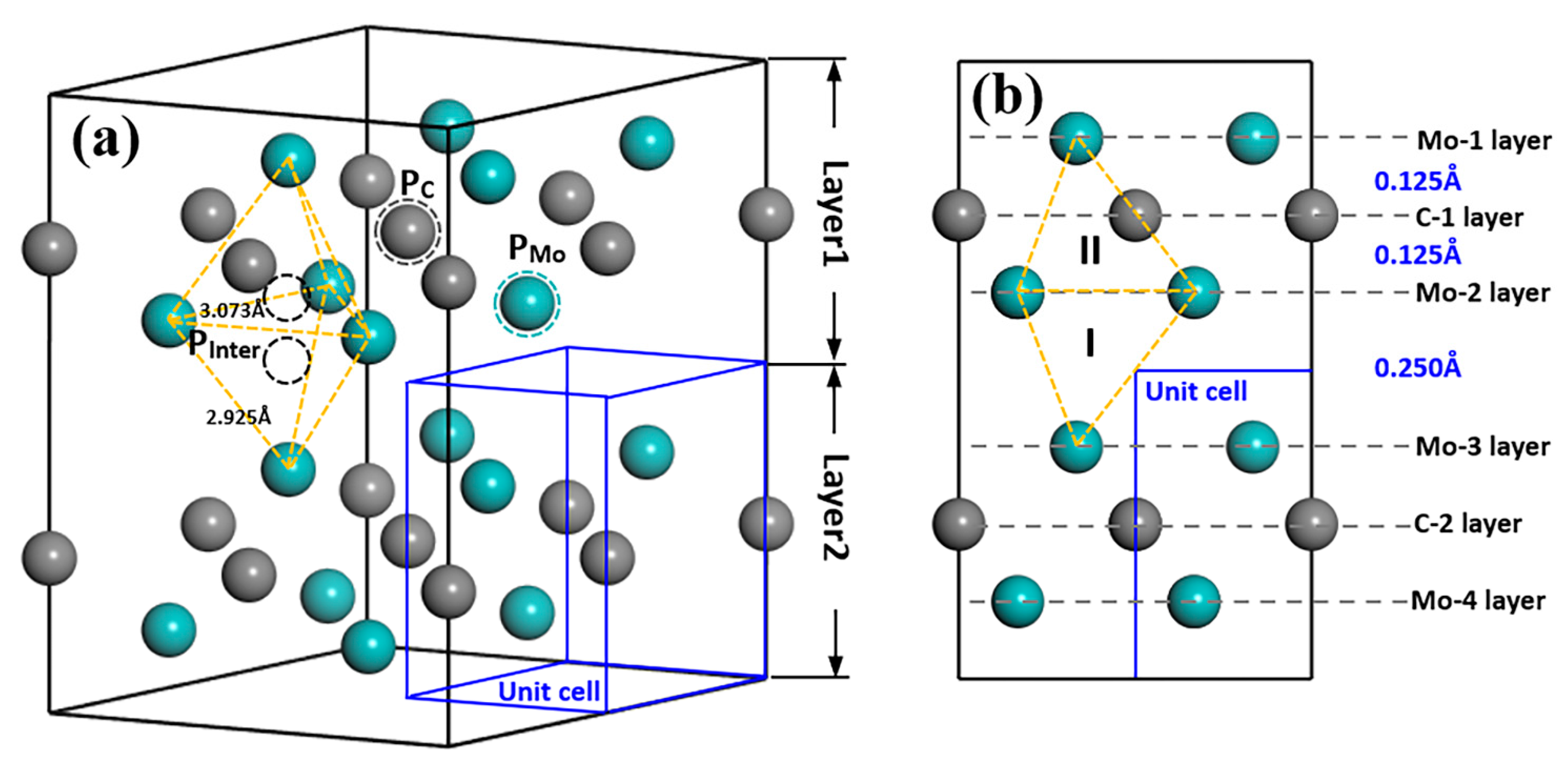
3.1.2. Structures and Electronic Properties
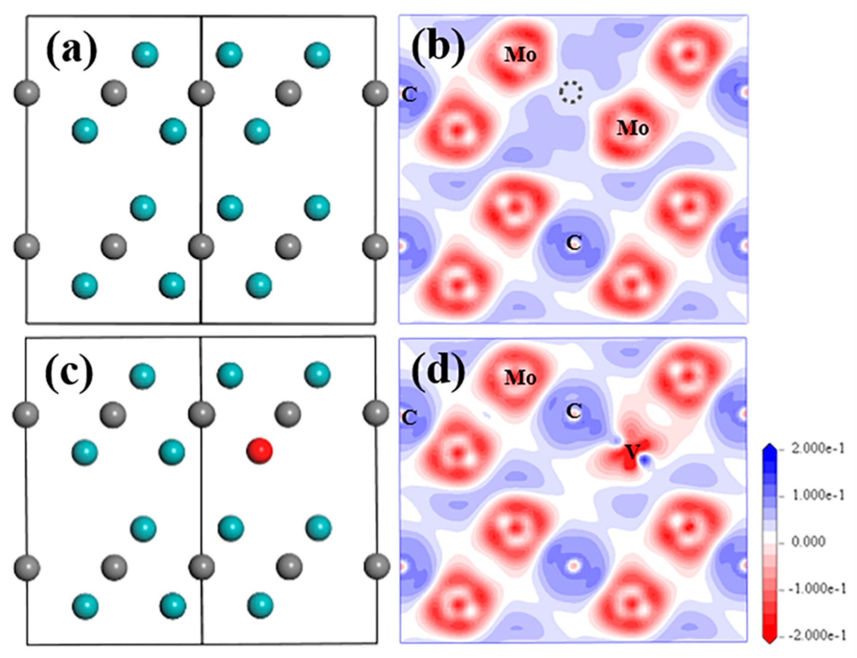
VC and SV-Mo
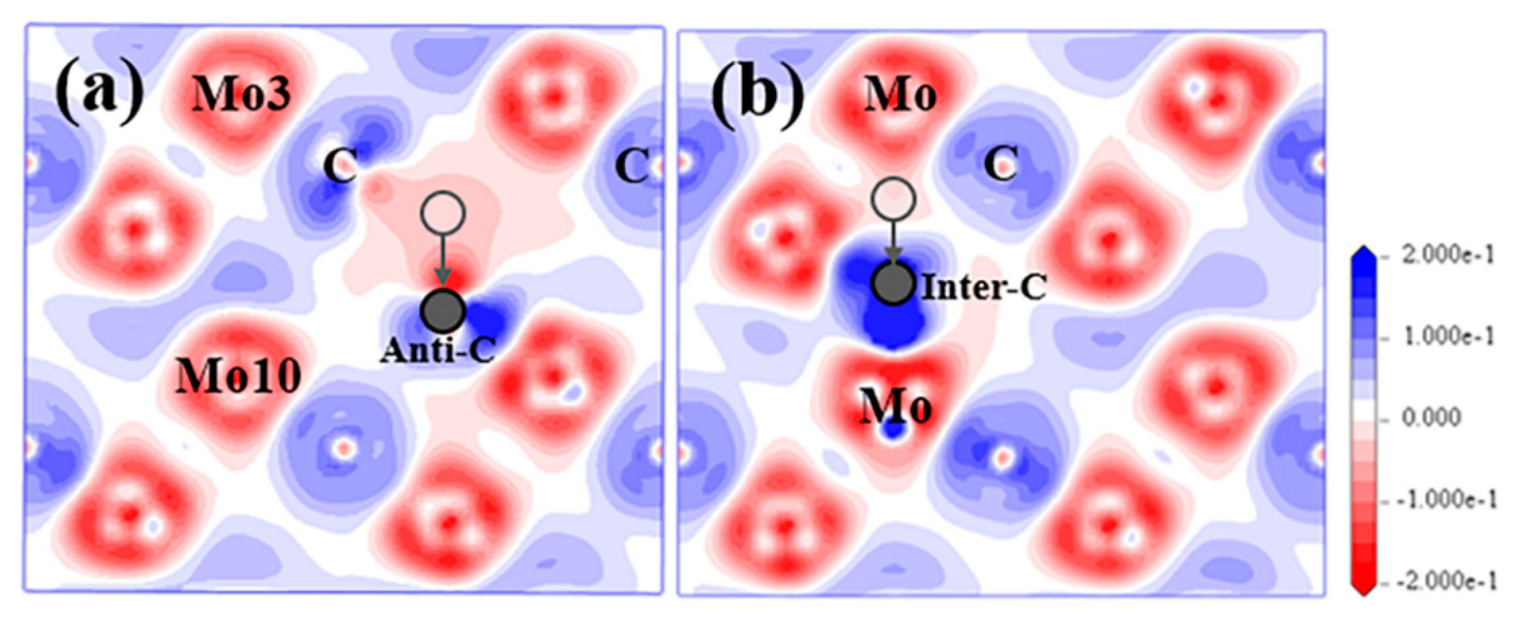
SC and IC
3.2. Defect Complexes
3.2.1. VMo+IC(I)
3.2.2. SV-Mo+VC
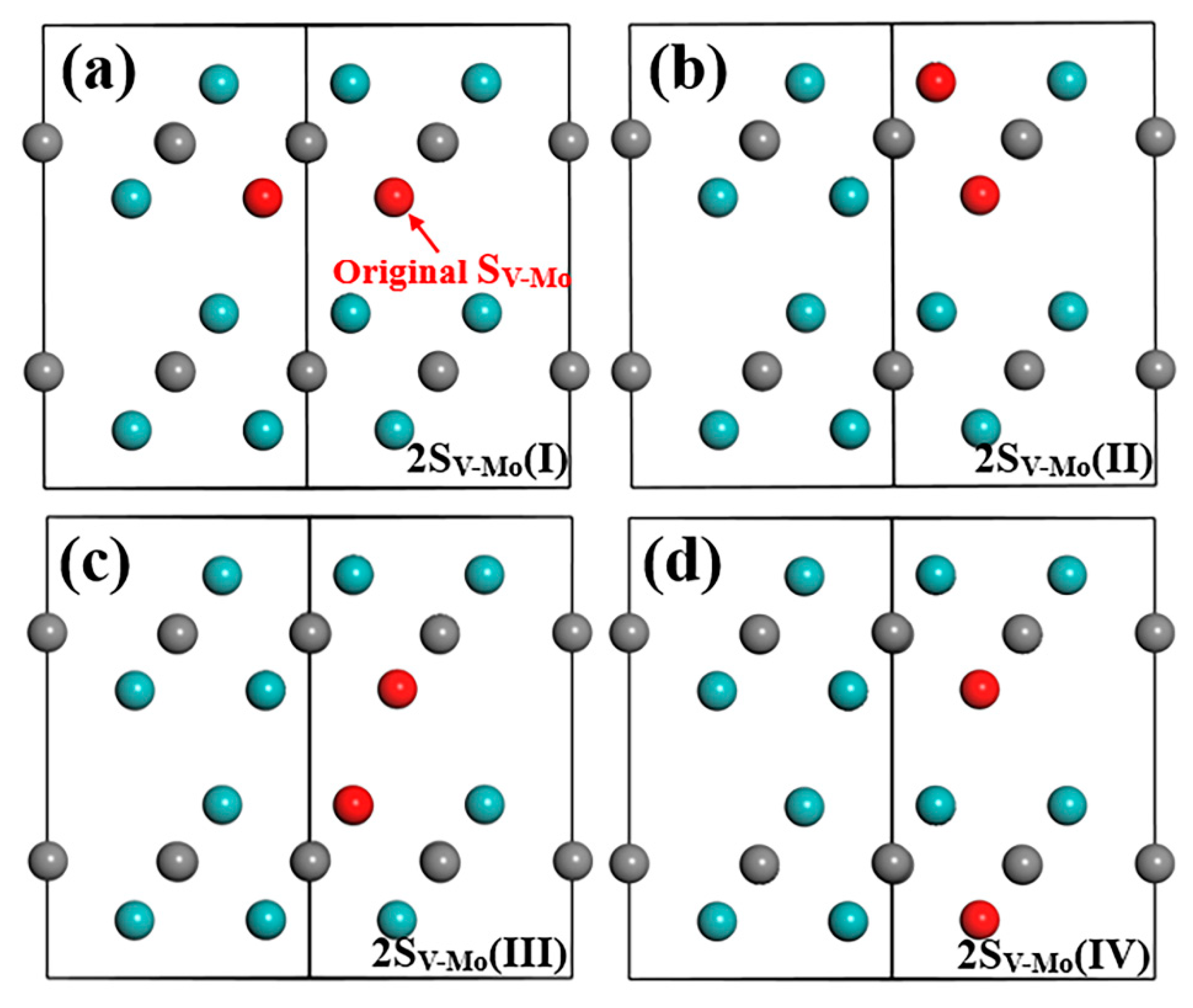
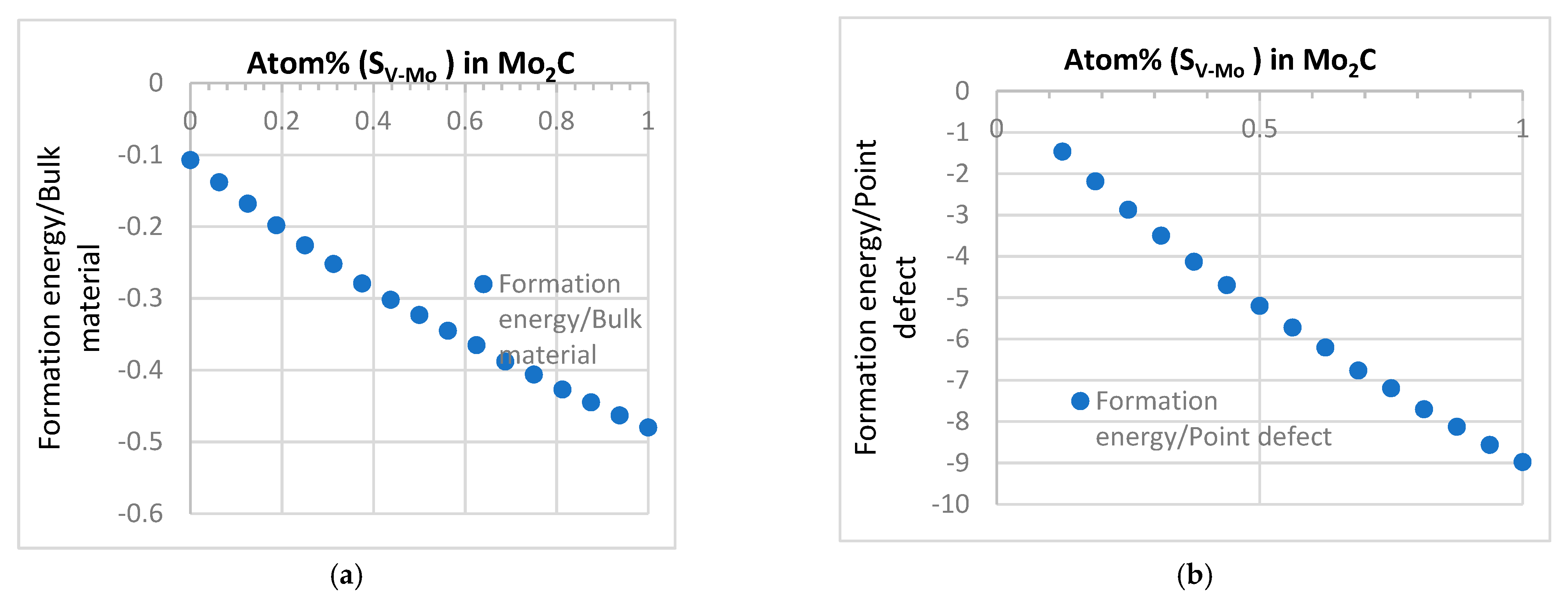
3.2.3. SV-Mo Defect Combinations
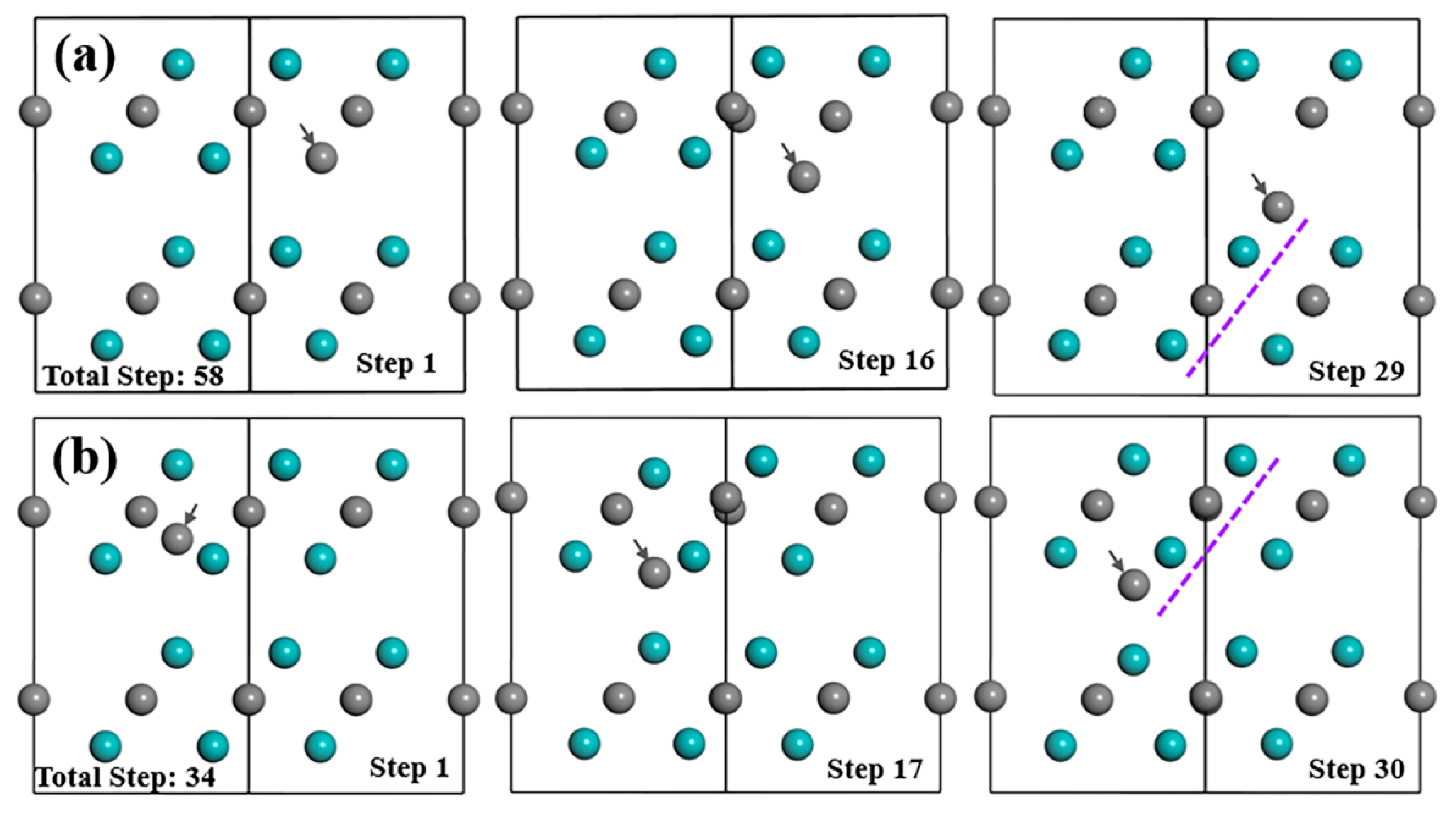
4. Discussion
5. Conclusions
Supplementary Materials
Author Contributions
Funding
Institutional Review Board Statement
Informed Consent Statement
Conflicts of Interest
References
- Hu, H.H.; Chen, J. Surface Chemistry of Transition Metal Carbides. Chem. Rev. 2005, 105, 185–212. [Google Scholar]
- Lukatskaya, M.R.; Kota, S.; Lin, Z.; Zhao, M.; Shpigel, N.; Levi, M.D.; Halim, J.; Taberna, P.; Barsoum, M.W.; Simon, P.; et al. Ultra-high-rate pseudocapacitive energy storage in two-dimensional transition metal carbides. Nat. Energy 2017, 2, 17105. [Google Scholar] [CrossRef]
- Harrington, T.J.; Gild, J.; Sarker, P.; Toher, C.; Rost, C.M.; Dippo, O.F.; McElfresh, C.; Kaufmann, K.; Marin, E.; Borowski, L.; et al. Phase stability and mechanical properties of novel high entropy transition metal carbides. Acta Mater. 2019, 166, 271–280. [Google Scholar] [CrossRef] [Green Version]
- Khazaei, M.; Arai, M.; Sasaki, T.; Chung, C.; Venkataramanan, N.S.; Estili, M.; Sakka, Y.; Kawazoe, Y. Novel Electronic and Magnetic Properties of Two-Dimensional Transition Metal Carbides and Nitrides. Adv. Funct. Mater. 2013, 23, 2185–2192. [Google Scholar] [CrossRef]
- Hantanasirisakul, K.; Gogotsi, Y. Electronic and Optical Properties of 2D Transition Metal Carbides and Nitrides (MXenes). Adv. Mater. 2018, 30, 1804779. [Google Scholar] [CrossRef]
- Li, D.; Liu, Y.; Ye, J.; Chen, X.; Wang, L. The enhancement of the microstructure and mechanical performances of ultrafine WC-Co cemented carbides by optimizing Cr2(C,N) addition and WC particle sizes. Int. J. Refract. Met. Hard Mater. 2021, 97, 105518. [Google Scholar] [CrossRef]
- Liu, S.; Wang, Z.; Guo, J.; Shi, Z.; Ren, X.J.; Yang, Q. Thermal-mismatch-stress induced deformation zone on primary-carbide/austenite interface. Mater. Lett. 2019, 248, 55–59. [Google Scholar] [CrossRef]
- Xie, Y.; Naguib, M.; Mochalin, V.N.; Barsoum, M.W.; Gogotsi, Y.; Yu, X.; Nam, K.; Yang, X.; Kolesnikov, A.; Kent, P. Role of Surface Structure on Li-Ion Energy Storage Capacity of Two-Dimensional Transition-Metal Carbides. J. Am. Chem. Soc. 2014, 136, 6385–6394. [Google Scholar] [CrossRef]
- Chen, W.; Muckerman, J.T.; Fujita, E. Recent developments in transition metal carbides and nitrides as hydrogen evolution electrocatalysts. Chem. Commun. 2013, 49, 8896–8909. [Google Scholar] [CrossRef]
- Geng, D.; Zhao, X.; Chen, Z.; Sun, W.; Fu, W.; Chen, J.; Liu, W.; Zhou, W.; Loh, K. Direct Synthesis of Large-Area 2D Mo2C on In Situ Grown Graphene. Adv. Mater. 2017, 29, 1700072. [Google Scholar] [CrossRef]
- Jia, J.; Xiong, T.; Zhao, L.; Wang, F.; Liu, H.; Hu, R.; Zhou, J.; Zhou, W.; Chen, S. Ultrathin N-Doped Mo2C Nanosheets with Exposed Active Sites as Efficient Electrocatalyst for Hydrogen Evolution Reactions. ACS Nano 2017, 11, 12509–12518. [Google Scholar] [CrossRef] [PubMed]
- Wang, T.; Wang, J.; Chen, W.; Zheng, X.; Wang, E. A Reusable N-Doped-Carbon-Coated Mo2C Composite Counter Electrode for High-Efficiency Dye-Sensitized Solar Cells. Chem. A Eur. J. 2017, 23, 17311–17317. [Google Scholar] [CrossRef] [PubMed]
- Patt, J.; Moon, D.; Phillips, C.; Thompson, L. Molybdenum carbide catalysts for water–gas shift. Catal. Lett. 2000, 65, 193–195. [Google Scholar] [CrossRef]
- Xiang, M.; Li, D.; Qi, H.; Li, W.; Zhong, B.; Sun, Y. Mixed alcohols synthesis from carbon monoxide hydrogenation over potassium promoted β-Mo2C catalysts. Fuel 2007, 86, 1298–1303. [Google Scholar] [CrossRef]
- Malpica-Maldonado, J.J.; Melo-Banda, J.A.; Martínez-Salazar, A.L.; Garcia-Hernández, M.; Díaz, N.P.; Meraz, M.A. Synthesis and characterization of Ni-Mo2C particles supported over hydroxyapatite for potential application as a catalyst for hydrogen production. Int. J. Hydrogen Energy 2019, 44, 12446–12454. [Google Scholar] [CrossRef]
- Zhao, Y.; Wang, S.; Liu, H.; Guo, X.; Zeng, X.; Wu, W.; Zhang, J.; Wang, G. Porous Mo2C nanorods as an efficient catalyst for the hydrogen evolution reaction. J. Phys. Chem. Solids 2019, 132, 230–235. [Google Scholar] [CrossRef]
- Liua, Z.; Lia, J.; Xue, S.; Zhou, S.; Qu, K.; Li, Y.; Cai, W. Pt/Mo2C heteronanosheets for superior hydrogen evolution reaction. J. Energy Chem. 2020, 47, 317–323. [Google Scholar] [CrossRef]
- Parthé, E.; Sadogopan, V. The structure of dimolybdenum carbide by neutron diffraction technique. Acta Crystallogr. 1963, 16, 202–205. [Google Scholar] [CrossRef]
- Wan, C.; Knight, N.A.; Leonard, B.M. Crystal structure and morphology control of molybdenum carbide nanomaterials synthesized from an amine–metal oxide composite. Chem. Commun. 2013, 49, 10409–10411. [Google Scholar] [CrossRef]
- Yamasaki, S.; Bhadeshia, H.K.D.H. Modelling and characterisation of Mo2C precipitation and cementite dissolution during tempering of Fe-C-Mo martensitic steel. Mater. Sci. Technol. 2003, 19, 723–731. [Google Scholar] [CrossRef]
- Haberkorn, N. Fabrication of β-Mo2C ultra-thin films by thermal annealing of molybdenum/carbon heterostructures. Mater. Lett. X 2019, 1, 100004. [Google Scholar] [CrossRef]
- Yang, L.; Zhai, T.; Jin, Y.; Leonhardt, T.; Li, W. Formation of Mo2C in molybdenum tubing inside a graphite furnace filled with pure nitrogen at high temperature. Int. J. Refract. Met. Hard Mater. 2021, 96, 105489. [Google Scholar] [CrossRef]
- Dantas, S.L.A.; Souza, A.L.R.; Bohn, F.; Lopes-Moriyama, A.L.; Souza, C.P.; Correa, M.A. Magnetic properties of Ni-doped Mo2C produced by fixed bed reactor. Mater. Lett. 2020, 273, 127916. [Google Scholar] [CrossRef]
- Zhao, Z.; Hui, P.; Wang, T.; Xu, Y.; Zhong, L.; Zhao, M.; Yang, D.; Wei, R. Fabrication of Mo2C coating on molybdenum by contact solid carburization. Appl. Surf. Sci. 2018, 462, 48–54. [Google Scholar] [CrossRef]
- Liu, H.; Zhu, J.; Lai, Z.; Zhao, R.; He, D. A first-principles study on structural and electronic properties of Mo2C. Scr. Mater. 2009, 60, 949–952. [Google Scholar] [CrossRef]
- Wang, X.R.; Yan, M.F.; Chen, H.T. First-Principles Calculations of Hardness and Melting Point of Mo2C. J. Mater. Sci. Technol. 2009, 25, 419–422. [Google Scholar]
- Liu, Y.; Jiang, Y.; Zhou, R.; Liu, X.; Feng, J. Elastic and thermodynamic properties of Mo2C polymorphs from first principles calculations. Ceram. Int. 2015, 41, 5239–5246. [Google Scholar] [CrossRef]
- Karaca, E.; Baǧcı, S.; Tütüncü, H.M.; Uzunok, H.Y.; Srivastava, G.P. Theoretical investigation of electron-phonon interaction in the orthorhombic phase of Mo2C. J. Alloys Compd. 2019, 788, 842–851. [Google Scholar] [CrossRef] [Green Version]
- Yang, J.; Pang, X.; Pang, M.; Zhao, Y.; Yang, W.; Zhan, Y. Understanding the influence of rare earth yttrium on surface characterizations of orthorhombic α-Mo2C(023) surface: A first-principle calculation approach. Surf. Sci. 2021, 708, 121823. [Google Scholar] [CrossRef]
- Hassan, A.; ZafarIlyas, S.; Ahmed, S.; Niaz, F.; Jalil, A.; Khan, Q. Ab-initio study of molybdenum carbide (Mo2C) as an adsorption-based filter. Phys. Lett. A 2021, 392, 127119. [Google Scholar] [CrossRef]
- Leitner, S.; Scheiber, D.; Dengg, T.; Spitaler, J.; Antretter, T.; Ecker, W. Analysis of shape, orientation and interface properties of Mo2C precipitates in Fe using ab-initio and finite element method calculations. Acta Mater. 2021, 204, 116478. [Google Scholar] [CrossRef]
- Sun, W.; Ehteshami, H.; Kent, P.; Korzhavyi, P. Self-diffusion of Ti interstitial based point defects and complexes in TiC. Acta Mater. 2019, 165, 381–387. [Google Scholar] [CrossRef]
- Razumovskiy, V.I.; Popov, M.N.; Ding, H.; Odqvist, J. Formation and interaction of point defects in group IVb transition metal carbides and nitrides. Comput. Mater. Sci. 2015, 104, 147–154. [Google Scholar] [CrossRef]
- Daroca, D.P.; Jaroszewicz, S.; Llois, A.M.; Mosca, H.O. First-principles study of point defects in thorium carbide. Journal of Nucl. Mater. 2014, 454, 217–222. [Google Scholar] [CrossRef]
- Ding, J.; Sun, D.; Yang, Y.; Huang, S.; Zhang, P.; Zhao, J. First-principles investigations of intrinsic point defects and helium impurities in vanadium monocarbide. Nucl. Instrum. Methods Phys. Res. Sect. B 2020, 479, 163–170. [Google Scholar] [CrossRef]
- Guo, J.; Liu, S.; Zhou, Y.; Wang, J.; Xing, X.; Ren, X.J.; Yang, Q. Stability of eutectic carbide in Fe-Cr-Mo-W-V-C alloy. Mater. Lett. 2016, 171, 216–219. [Google Scholar] [CrossRef] [Green Version]
- Guo, J.; Ai, L.; Wang, T.; Feng, Y.; Wan, D.; Yang, Q. Microstructure evolution and micro-mechanical behavior of secondary carbides at grain boundary in a Fe-Cr-W-Mo-V-C alloy. Mater. Sci. Eng. A 2018, 715, 359–369. [Google Scholar] [CrossRef]
- Guo, J.; Liu, L.; Feng, Y.; Liu, S.; Ren, X.; Yang, Q. Crystallographic characterizations of eutectic and secondary carbides in a Fe-12Cr-2.5Mo-1.5W-3V-1.25C alloy. Met. Mater. Int. 2017, 23, 313–319. [Google Scholar] [CrossRef]
- Guo, J.; Liu, L.; Li, Q.; Sun, Y.; Gao, Y.; Ren, X.J.; Yang, Q. Characterization on carbide of a novel steel for cold work roll during solidification process. Mater. Charact. 2013, 79, 100–109. [Google Scholar] [CrossRef]
- Guo, J.; Liu, L.; Liu, S.; Zhou, Y.; Qi, X.; Ren, X.; Yang, Q. Stability of eutectic carbide in Fe-Cr-Mo-W-V-C alloy by first-principles calculation. Mater. Des. 2016, 106, 355–362. [Google Scholar]
- Guo, J.; Feng, Y.; Tang, C.; Ren, X. Intrinsic defects, Mo related defects and complexes in transition metal carbide VC: A first-principles study. J. Am. Ceram. Soc. 2020, 103, 7226–7239. [Google Scholar] [CrossRef]
- Yu, X.; Thompsona, G.; Weinberger, C. Influence of carbon vacancy formation on the elastic constants and hardening mechanisms in transition metal carbides. J. Eur. Ceram. Soc. 2015, 35, 95–103. [Google Scholar] [CrossRef]
- Ivashchenko, V.I.; Turchi, P.E.A.; Shevchenko, V.I.; Ivashchenko, V.; Gorb, L.; Leszczynski, J. Properties of molybdenum carbides and the Ti–Mo–C solid solutions: A first-principles study. Solid State Comm. Mater. Chem. Phys. 2022, 275, 1–17. [Google Scholar]
- Liu, L.; Yu, Y.; Kuang, F.; Zhou, S.; Gong, H. First principles calculation on cohesion properties of PdCu-Mo2C interfaces. Surface Sci. 2022, 716, 121962. [Google Scholar] [CrossRef]
- Wei, M.; Jian, S.; Wen, Y. A first-principles study of displacive β to ω transition in Ti-V alloys. Prog. Nat. Sci. 2017, 27, 703–708. [Google Scholar]
- Shi, X.; Wang, S.; Wang, H.; Deng, C.; Qin, Z.; Wang, J. Structure and stability of b-Mo2C bulk and surfaces: A density functional theory study. Surf. Sci. 2009, 603, 852–859. [Google Scholar] [CrossRef]
- Zhou, Z.; Shan, Q.; Jiang, Y.; Li, Z.; Zhang, Z. Effect of nanoscale V2C precipitates on the three-body abrasive wear behavior of high-Mn austenitic steel. Wear 2019, 436–437, 203009. [Google Scholar] [CrossRef]
- Deng, B.; Wang, Z.; Chen, W.; Li, J.T.; Luong, D.; Carter, R.; Gao, G.; Yakobson, B.; Zhao, Y.; Tour, J.M. Phase controlled synthesis of transition metal carbide nanocrytsals by ultrafast flash joule heating. Nat. Commun. 2022, 13, 262. [Google Scholar] [CrossRef]
- Zhu, H.; Zhai, L.; Li, J.; Xiao, F. First-Principle Study on the Stability of Lightly Doped (Nb1−xTix)C Complex Carbides and Their Verification in 1045 Steel. ACS Omega 2021, 6, 19964–19972. [Google Scholar] [CrossRef]
- Cotter, C.; Frank, B.; Zhang, W.; Schlögl, R.; Trunschke, A. The Impact of V Doping on the Carbothermal Synthesis of Mesoporous Mo. Chem. Mater. 2013, 25, 3124–3136. [Google Scholar] [CrossRef]
- Zhang, C.; Wu, S.; Luo, S.; Wang, Y.; Li, J.; Leng, Y. Vanadium-doped Molybdenum Carbides as Promising Catalyst for C-N/C-C coupling reactions. N. J. Chem. 2020, 44, 9736–9742. [Google Scholar] [CrossRef]
- Cotter, T.; Girgsdies, F.; Zhang, W. Synthesis of stable V-doped Mo2C with high surface area. In Proceedings of the 27th North American Catalysis Society Meeting (NAM27), New York, NY, USA, 23–28 May 2021. [Google Scholar]
- Yamasaki, S. Modelling Precipitation of Carbides in Martensitic Steels. Ph.D. Thesis, University of Cambridge, Cambridge, UK, 2004; p. 5. [Google Scholar]
- Seo, H.; Heo, Y.; Kim, J.; Lee, J.; Choi, S.; Lee, C. Effect of V/Mo Ratio on The Evolution of Carbide Precipitates and Hydrogen. Embrittlement of Tempered Martensitic Steel. Corros. Sci. 2020, 176, 108929. [Google Scholar] [CrossRef]
- Qin, T.; Wang, Z.; Wang, Y.; Besenbacher, F.; Otyepka, M.; Dong, M. Recent Progress in Emerging Two-Dimensional Transition Metal Carbides, Recent Progress in Emerging Two-Dimensional Transition Metal Carbides. Nano Micro Lett. 2021, 13, 183. [Google Scholar] [CrossRef]
- Gong, P.; Liu, X.G.; Rijkenberg, A.; Rainforth, W.M. The effect of molybdenum on interphase precipitation and microstructures in microalloyed steels containing titanium and vanadium. Acta Mater. 2018, 161, 374–387. [Google Scholar] [CrossRef] [Green Version]
- laIoannidou, C.; Arechabaleta, Z.; Navarro-López, A.; Rijkenberg, A.; Dalgliesh, R.M.; Kölling, S.; Bliznuk, V.; Pappas, C.; Sietsmaa, J.; van Wellf, A.; et al. Interaction of precipitation with austenite-to-ferrite phase transformation in vanadium micro-alloyed steels. Acta Mater. 2019, 181, 10–24. [Google Scholar] [CrossRef] [Green Version]
- Reveil, M.; Wang, J.; Thompson, M.O.; Clancy, P. Preferred diffusional pathways of intrinsic defects and silicon dopants in an ordered phase of In0.5Ga0.5As: A first-principles study. Acta Mater. 2017, 140, 39–45. [Google Scholar] [CrossRef]
- Ren, Z.; Xue, Z.; Zhang, X.; Qin, J.; Ma, M.; Liu, R. Atomic diffusion mediated by vacancy defects in L12-Zr3Al: A first-principles study. J. Alloys Compd. 2020, 821, 1532232. [Google Scholar] [CrossRef]
- Shi, T.-T.; Wang, J.N.; Wang, Y.P.; Wang, H.C.; Tang, B.Y. Atomic diffusion mediated by vacancy defects in pure and transition element (TM)-doped (TM = Ti, Y, Zr or Hf) L12Al3Sc. Mater. Des. 2016, 108, 529–537. [Google Scholar] [CrossRef]


| Supercell | Formation Energy | |
|---|---|---|
| Point Defect | Bulk Material | |
| Perfect | −0.051 | |
| VMo | 3.833 | 0.071 |
| VC | 0.410 | −0.039 |
| SMo | 7.487 | 0.205 |
| SC | 4.232 | 0.070 |
| IMo(I,II) | 10.252 | 0.308 |
| IC(I,II) | 3.210 | 0.026 |
| SV-Mo | −0.761 | −0.138 |
| SV-C | 5.623 | 0.128 |
| IV(I) | 7.820 | 0.211 |
| IV(II) | 6.991 | 0.177 |
| Defect | Atomic Charge (e) | Bond Population | |||
|---|---|---|---|---|---|
| Mo | C | V | Mo–C Bond | V–C Bond | |
| VMo | 0.36, 0.21, 0.07 | −0.61, −0.54 | — | 0.51, 0.42, 0.35, 0.30, 0.27, 0.13 | — |
| VC | 0.28, 0.26 | −0.61 | — | 0.41, 0.33, 0.28 | — |
| SMo | 0.31, 0.22, −0.1 | −0.61, −0.58 | — | 0.43, 0.33 | — |
| SC | 0.43, 0.34, 0.16 | −0.62, −0.54, −0.37 | — | 0.63, 0.53, 0.42, 0.37, 0.32, 0.27, 0.13 | — |
| IMo(I) | 0.54, 0.34, 0.28, 0.09, −0.02 | −0.61 | — | 0.4, 0.36, 0.32, 0.23, 0.12 | — |
| IMo(II) | 0.54, 0.34, 0.28, 0.09, −0.02 | −0.61 | — | 0.4, 0.36, 0.32, 0.23, 0.12 | — |
| IC(I) | 0.44, 0.33, 0.29, 0.23 | −0.61, −0.58 | — | 0.38, 0.36, 0.33, 0.29, 0.26 | — |
| IC(II) | 0.44, 0.33, 0.29, 0.23 | −0.61, −0.58 | — | 0.38, 0.36, 0.33, 0.29, 0.26 | — |
| SV-Mo | 0.29, 0.26 | −0.61 | 0.71 | 0.38, 0.32 | 0.23 |
| SV-C | 0.32, 0.26, 0.13 | −0.6 | 0.33 | 0.36, 0.33 | — |
| IV(I) | 0.34, 0.31, 0.11, 0.05 | −0.61 | 0.56 | 0.36, 0.31, 0.12 | −0.04 |
| IV(II) | 0.33, 0.29, 0.11, 0.07 | −0.6 | 0.52 | 0.36, 0.31, 0.15 | 0 |
| Defect | Atomic Charge (e) | Bond Population | |||
|---|---|---|---|---|---|
| Mo | C | V | Mo–C Bond | V–C Bond | |
| VMo+IC | 0.43, 0.34, 0.15 | −0.62, −0.54, −0.37 | — | 0.64, 0.53, 0.42, 0.37, 0.32, 0.27, 0.13 | — |
| SV-Mo+VC | 0.26, 0.23, 0.21 | −0.61 | 0.64 | 0.45, 0.40, 0.33, 0.28 | 0.21 |
| Supercell | Total Energy | Formation Energy | Binding Energy | |
|---|---|---|---|---|
| Point Defect | Bulk Material | |||
| VMo+IC | −30,446.788 | 4.307 | 0.073 | 1.635 |
| SV-Mo+VC | −32,116.798 | 0.641 | −0.083 | −0.768 |
| Supercell | Total Energy | Formation Energy | Binding Energy | |
|---|---|---|---|---|
| Point Defect | Bulk Material | |||
| 2SV-Mo(I) | −32,313.597 | −1.464 | −0.168 | −0.058 |
| 2SV-Mo(II) | −32,313.602 | −1.464 | −0.168 | −0.058 |
| 2SV-Mo(III) | −32,313.615 | −1.464 | −0.168 | −0.058 |
| 2SV-Mo(IV) | −32,313.642 | −1.464 | −0.168 | −0.058 |
Publisher’s Note: MDPI stays neutral with regard to jurisdictional claims in published maps and institutional affiliations. |
© 2022 by the authors. Licensee MDPI, Basel, Switzerland. This article is an open access article distributed under the terms and conditions of the Creative Commons Attribution (CC BY) license (https://creativecommons.org/licenses/by/4.0/).
Share and Cite
Guo, J.; Feng, Y.; Tang, C.; Wang, L.; Qing, X.; Yang, Q.; Ren, X. Insight into Point Defects and Complex Defects in β-Mo2C and Carbide Evolution from First Principles. Materials 2022, 15, 4719. https://doi.org/10.3390/ma15134719
Guo J, Feng Y, Tang C, Wang L, Qing X, Yang Q, Ren X. Insight into Point Defects and Complex Defects in β-Mo2C and Carbide Evolution from First Principles. Materials. 2022; 15(13):4719. https://doi.org/10.3390/ma15134719
Chicago/Turabian StyleGuo, Jing, Yunli Feng, Cong Tang, Li Wang, Xiaoliang Qing, Qingxiang Yang, and Xuejun Ren. 2022. "Insight into Point Defects and Complex Defects in β-Mo2C and Carbide Evolution from First Principles" Materials 15, no. 13: 4719. https://doi.org/10.3390/ma15134719
APA StyleGuo, J., Feng, Y., Tang, C., Wang, L., Qing, X., Yang, Q., & Ren, X. (2022). Insight into Point Defects and Complex Defects in β-Mo2C and Carbide Evolution from First Principles. Materials, 15(13), 4719. https://doi.org/10.3390/ma15134719